However, in this case we wanted a kind of “special” setup which included the use of MultiPlus Assistants. So, in this article I will quickly describe what we wanted to achieve and how we implemented it.
In general, when connected to shore power we want to be able to limit the AC current drawn from the shore power. This is easily accomplished by setting a limit on the MultiPlus itself – or, as in our case, via the VE.BusSmart Dongle. Though the Phoenix does have a VE.Direct interface and is able to be connected to a GX device, in our setup we did not want to use a GX device. So, essentially the Phoenix can only be controlled via Bluetooth and the VictronConnect app. But configuring the AC input limit on two devices (Phoenix and MultiPlus) is not only a nuisance from a usability standpoint, but also error-prone as one (or at least we) tend to forget things quickly. So, a different and better solution was needed.
Enter the MultiPlus Assistant in form of the Programmable Relay. With this, we can configure the built-in relay of the MultiPlus to open and close based on the availability of an AC input.
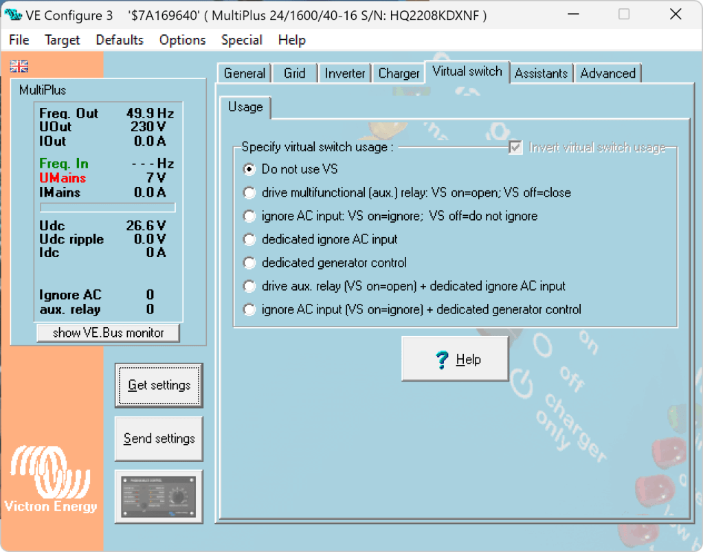
Note: we have to disable “Virtual Switch” in the MultiPlus to be able to use the MultiPlus Assistant.
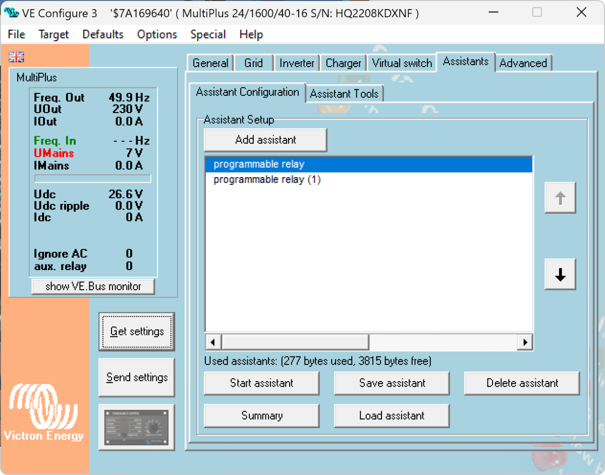
The Phoenix has a Remote Input connector, that can be used to stop charging when the connection is “off”. So in our case, we enabled two Programmable Relay assistants:
Programmable Relay, NC – On/Open After 5 seconds of AC input on the MultiPlus the relay is opened.
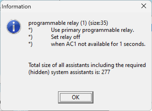
Programmable Relay, NC – Off/Closed After 1 second of no AC input on the MultiPlus the relay is closed (which is the default state).
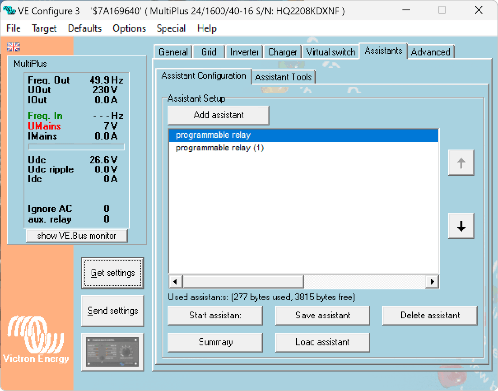
Below you find some screenshots with the configuration in VE Configure:
Disable Virtual Switch on MultiPlusAdd 2 Progammable Relay assistantsProgrammable Relay ON after 5 secondsProgrammable Relay OFF after 1 second
So, five seconds after the MultiPlus has power via AC input it will open the relay which in turn will enable the Phoenix to start charging.
One second after AC input is gone the MultiPlus will close the relay so the Phoenix will stop charing (if it was charging at all).
The AC input of the Phoenix is connected to the AC output of the MultiPlus. So, when there is a AC input limit configured on the MultiPlus (such as 3A @230V) the MultiPlus and the Phoenix will not be able to charge with more than 3A. And from the MultiPlus perspective, the Phoenix is just an arbitrary consumer.
This can lead to some undesired behaviour if we were to limit the AC input to e.g. 1A. In this case, the MultiPlus would – when in Inverter mode – draw from the battery so the Phoenix could charge the battery. perpetuum mobile … ? And when the AC input is gone, this means that for roughly one second the Phoenix will also charge form the battery. But this is something I can live with easily.
And if we really had a very low power AC input (of e.g. 1A) we can still unplug the remote input and force the Phoenix not to charge. Or manually switch the MultiPlus to Charger mode only.
For us this is a usable solution without the need for multiple configuration changes nor the presence of a GX device.
Now, that we got our Toyota HiAce we thought it might be a good idea to add more power to the vehicle: in form of an 8s EVE LF280K LiFePO4 battery and a Victron MultiPlus Compact 24/1600/40-16 inverter/charger. In the following, we describe our setup and the reason why we built it like this.
The Requirements
The sustained output power of the inverter must be over 1'200W.
Charging via AC via EVSE or generator must be possible.
Charging via alternator must be possible (but is not the norm).
Charging of 60% of the battery (from 20% – 80%) via AC should take less than 180min.
The installation should use the minimum amount of space possible.
We should be able to use our existing Eve LF280K cells, thus limiting the overall current to 140A.
As the vehicle will not have a diesel heater, it should be possible to run a 150W infrared heater for at least 3 * (4+2)h = 18h (^= 2'700Wh).
In addition, the battery should be able to run a refrigerator with an average power consumption of 50W for at least 72h ^= 3'600Wh (next to other power consumption).
Design Considerations
With a maximum current of 140A and a cable run length of 1.5m, we should plan with a cross section of at least 35mm2.
Basically, with Eve LF280K cells we have three choices regarding the battery size:
1* 4s (“12V”) Configuration 4 * 3.2V * 280Ah = 3'584Wh This would lead to a required nominal AC charge power of at least 716.8W/h and a charge current of at least 56A/h.
2* 4s (“12V”) Configuration 2* 4 * 3.2V * 280Ah = 7'168Wh This would lead to a required nominal AC charge power of at least 1'433.6W/h and a charge current of at least 112A/h.
1* 8s (“24V”) Configuration 8 * 3.2V * 280Ah = 7'168Wh This would lead to a required nominal AC charge power of at least 1'433.6W/h and a charge current of at least 56A/h.
The Victron MultiPlus Compact xx/1600VA inverter/charger provides enough sustained power output (while being smaller than the non-Compact edition). Depending on the voltage of the battery, this will slightly impact the amount of charge current.
To charge the battery via the alternator we would need a DC/DC converter that depends on the battery configuration as well (either 12-12 or 12-24). So, let’s have a look at the battery first.
1* 4s (“12V”) Configuration
The smallest, lightest and cheapest configuration. But capacity requirements regarding the fridge are only fulfilled, if there are no other loads. In addition, the discharge current is relatively high (scratching the maximum discharge rate of 0.5C).
2* 4s (“12V”) Configuration
More complex setup, as each battery needs a separate BMS, which leads to the need of an aggregator for both batteries to correctly report SoC and calculate CCL and DCL. In addition, more cabling and fusing is required (and probably to a large bus bar). Comes with the advantage of having a redundant battery in case a single battery fails. Most expensive configuration.
1* 8s (“24V”) Configuration
Custom battery build needed, as there is not enough space for a typical 2 * 4 cells setup behind he seats. But, only a single BMS and thus less wiring is needed. Comes with a slight disadvantage of not having native 12V from the battery. This is actually not an isse, as all our DC devices also accept 24V. Cells can better balance voltage differences across a single 8s bank.
The Setup
In the end, I decided for the 8s configuration, due to less complexity. Splitting the 8s configuration across two cell blocks seemed to be an acceptable compromise.
As a regular MultiPlus 24/1600/40-16 would not fulfill my AC charge requirements, I had to decide to either add a second MultiPlus or to add a dedicated charger. I opted for a Phoenix Smart IP43 Charger 24/25 instead of a second MultiPlus. The MultiPlus in parallel would always consume 10W though most of the time I would not need the output power. Whereas, the Phoenix would only need power, when connected to AC. And reconfiguring the MultiPlus every time I charge was not an option for me. And yes, I lose redundancy – but also save some money (Phoenix is much cheaper). So, in the end the nominal charge power is 40A + 25A = 65A, which lets me charge at 1'560W reaching 60% within 165min.
The HiAce comes with a 70A alternator, so I chose a Orion-Tr Smart 12/24-15 DC-DC Charger. With this charger, I could run the engine in standby and still have the car heater running. And this is probably the predominant use case (if charging via alternator at all).
For the DC bus bar I went for a Victron Lynx Distributor, so I could use and install MEGA fuses. Having a 1’000A bus bar seems certainly overkill, but a separate bus bar and fuse box that accepts 35mm2 cable and MEGA fuses would be not be much smaller.
I changed the existing AC inlet of the HiAce to Neutrik PowerCON True1 TOP (congrats to the marketing department, I am still amazed how this name rolls of the tongue) and installed 2 Siemens compact 16A CRCBOs (external AC in, internal AC out). I am aware that theoretically I could support more than 16A on the internal AC out (via PowerAssist). If ever needed, I can replace the RCBO with a 20A version.
I added a VE.Bus Smart Dongle to the MultiPlus and opted against a complete (Raspberry-based) GX installation. The reason, I keep a USBMK3 with me anyway (in case I need to reconfigure the MultiPlus) and still have (Bluetooth) access to the most important settings and information of the MultiPlus. With the GX, I would to be running a WiFi hotspot (and consuming more energy as well). The disadvanage of not being able to use DVCC with information from the BMS is clear to me and accepted.
I selected a B2A8S20P JK-BMS that has an integrated 2A balancer and an RS485, CAN and heat port. In case, I ever add a GX device, I am still able to connect them and use DVCC.
The Specs
Nominal power (“capacity”) 8 * 3.2V * 280Ah = 7'168Wh
Maximum discharge power 1’600VA (1'280W, capped by the inverter) with a maximum current of 80A/63A/55A (at 2.5V/3.2V/3.65V)
Maximum AC charge power 1'560W
AC Charging from 20% – 80% in 165min
Maximum DC charge power 360W
MultiPlus self-power consumption 10W
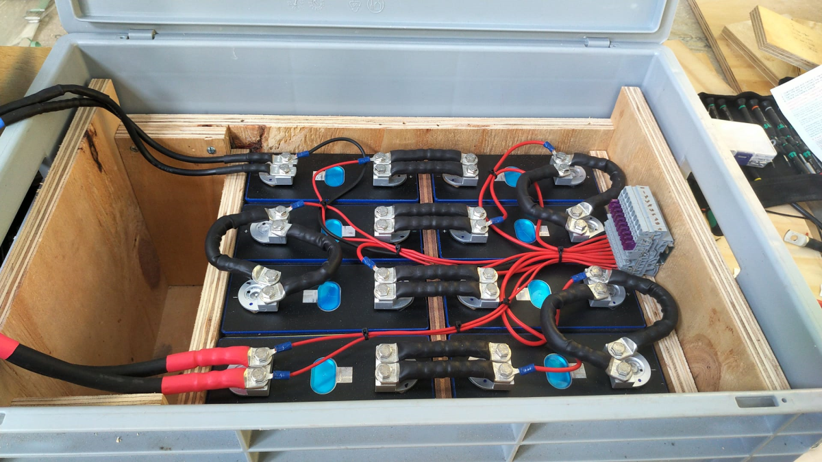
The Build
As mentioned before, due to space constraints I had to split the battery in 2 parts (with each having 4 cells). Instead of using utz RAKO boxes I used 12mm (sanded) plywood which I did not screw together but tied down with a banding/tensioning tool and a ratchet strap. With this setup, I can easily access und disassemble the cells if needed, while still having a sturdy case. Both cell blocks are connected with a (blue) Anderson SB175 connector.
The BMS itself is mounted to the side of one of the cases (I took extra care to use short screws, in order not to drill into the cell casing). I used M6 Weidmüller 35mm2 90° angled compression cable lug to get the wire away from the BMS and into the bus bar. All other compression cable lugs are DIN 46235 from Klauke (M6 35mm2 on the cells, and M8 16mm2/35mm2 on the bus bar).
The AC and DC wires are all Eland H07RN-F (except for the last two points):
Charger to bus bar, battery to bus bar: 35mm2
Cell block to cell block: 2 * 35mm2
Alternator to DC-DC converter, DC-DC converter to bus bar: 16mm2
External AC in to RCBO, RCBO to inverter/charger (both directions), RCBO to internal AC out: 3G2.5mm2
For the connection of the Inverter/charger to the bus bar, I used the Victron installed 25mm2 welding cables.
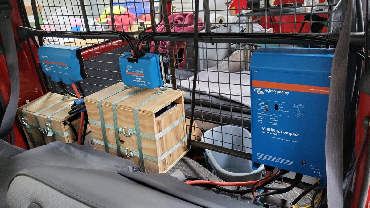
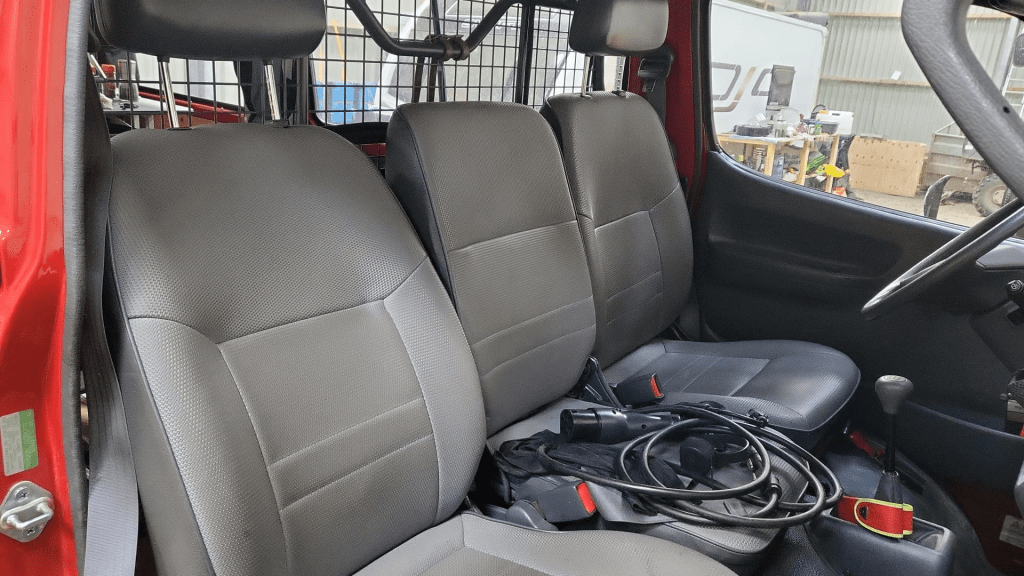
Images
The installation is barely visible behind the seatsView from the back with preliminary wiringConnection of cell blocks with SB175 connectors, cell block 2 and DC-DC converterLynx Distributor with cell block 1Inverter/charger with space for second charger and cell block 2 (left)
Note: the Phoenix charger is not visible on the images, as I am still waiting for it to be delivered.
Charging via EVSE
Conclusion
We now have more than 7'000Wh of additional energy without losing any storage space for roughly 2'850 CHF/2’500 GBP (parts without labour). We can survive an extended weekend of 72h without recharging while still being able to enjoy amenities as using a coffee machine, heating and refrigerator. In case of longer periods of usage, we can recharge at any EVSE, or via shore power. And in emergencies, we can also charge via our Honda EU10i or via the alternator of the vehicle.
The battery is placed directly over the engine which helps in cold weather conditions to easily warm up the batteries to a chargeable level.
The other day, I received my Victron MultiPlus Compact 12/1600/70-16. One of the first steps to do upon commissioning was to update the firmware. In my case from v481 to v502.
With my Windows PC running the latest VictronConnect App and a MK3 to USB-C Interface, I connected to the MultiPlus and enabled the advanced settings by entering the infamous zzz password (which you officially can only get from an official Victron training or distributor or simply by searching the internet).
I was offered to install 2606502.vff to which I happily clicked OK. So it seemed, I was running on a new microcontroller with 230V (hence 26) and really had a MultiPlus Compact 12/1600 (06). But I did not know this at that time.
After a couple of seconds into the update process, the operation stopped by telling me something failed. And after a restart, the only thing I could see was the yellow LED constantly flashing as soon as power was connected to the device and regardless of the main switch position.
Victron MultiPlus Compact flashes yellow after failed firmware update
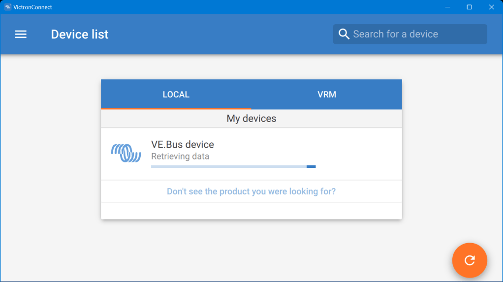
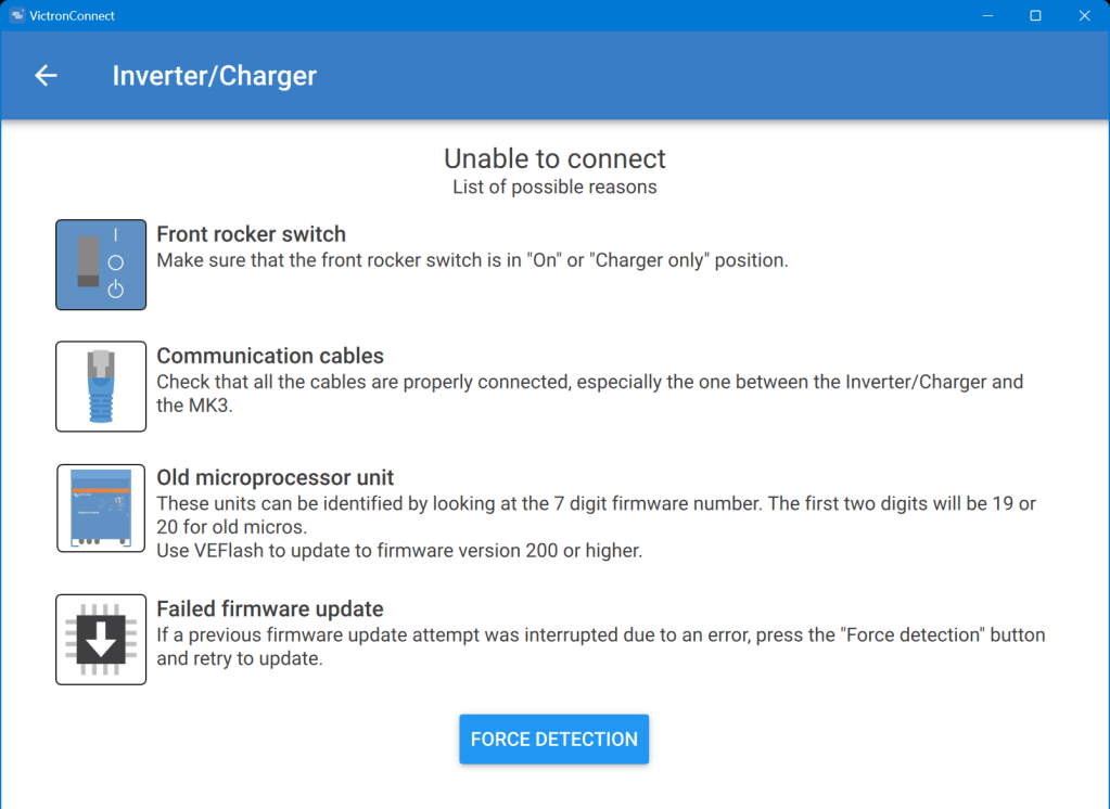
When I tried to reconnect with the VictronConnect app, the detection phase took very long – but the MultiPlus was not recognised.
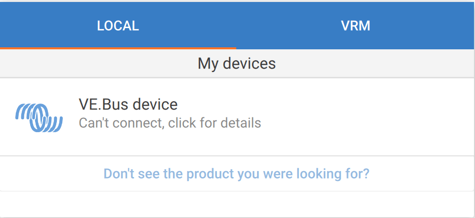
VictronConnect trying to detect the MultiPlus after the failed firmware updateDetection unsuccessful after the failed firmware update
Even when I tried the “Force detection” option (which is intended to be used after a failed firmware update) no usable result was yielded.
“Force detection” did not work either
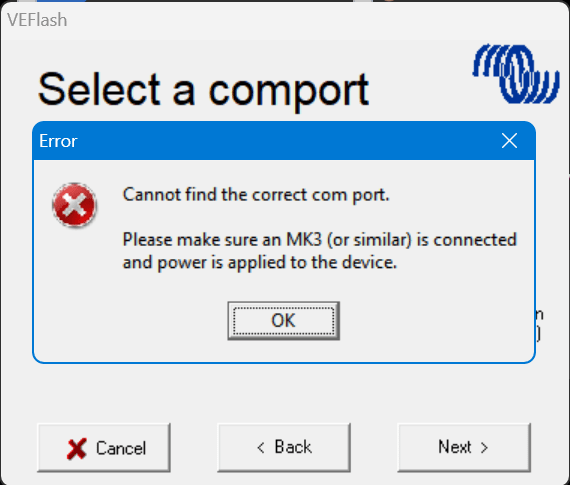
So, then I resorted to VEFlash (which is deprecated and has to be selected explicitly when installing the Victron tools on Windows).
But this did not work either, as it could not find anything behind the MK3:
VEFlash failed to recognise the MultiPlus
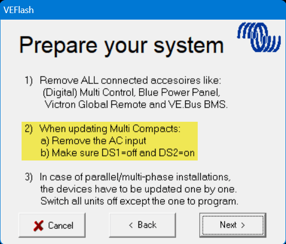
However, having a closer look at the hints VEFlash gave me before the recovery I was confused that VEFlash asked me to unplug the AC power source. How would I be able to update the firmware? Via DC? And why would it matter anyway which power source was connected?
VEFlash hint at not using AC power on a MultiPlus Compact
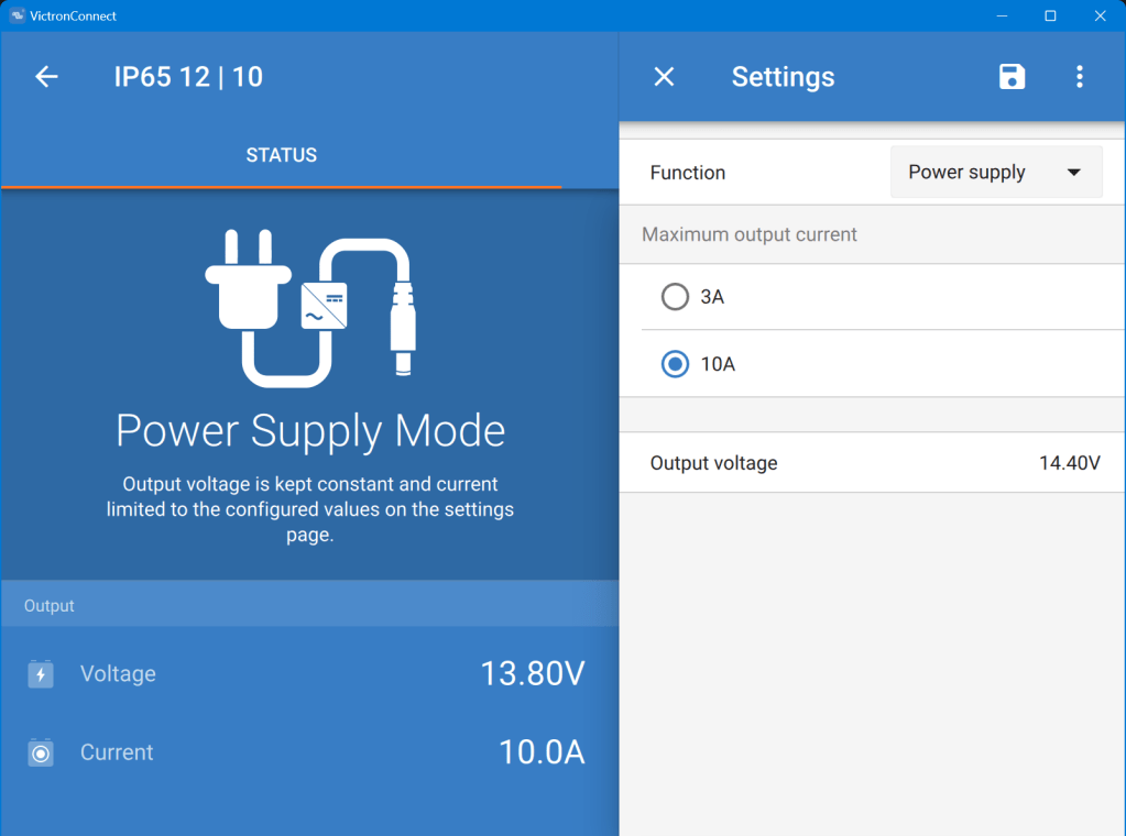
Using a Blue Smart Charger as a DC power source for the MultiPlus
As soon as I connected a Blue Smart IP65 Charger in “Power Supply” mode to it (and configured a voltage of 14.4V) the “Force detection” option in VictronConnect worked.
Note1: I did not alter any of the DIP switches as recommended by VEFlash.
In one of our previous articles, we stated that, due to power, weight and size, we would rather go for a 24V 8s (280Ah) battery configuration instead of 48V 16s.
However, there are relatively few battery cases for 8s battery packs that fit our Eve LF280K cells. And they are pricey! So, instead of spending a 500+ USD per case, I was thinking to repeat what others have done before me: build a case myself. And certainly, I took inspiration from variousothers and commercialkits.
So first, here are my requirements:
Case must fit 8 EVE LF280K cells including all electronics and cabling such as BMS, MCB, GX.
Battery must be pluggable to the inverter via Anderson SB 175 connector. Check: why not use Amphenol sockets/plugs?
Case must not absorp moisture/liquids that would build up from below.
Case must have no external display or buttons (i.e. solid walls).
Cells must be insulated against each other.
Cells must be fixed to the case so the do not fly around when the box is moved.
Battery status should be readable from the box itself (optional).
The case should be usable independant of any BMS.
Battery is meant to be used 1:1 with a single inverter.
Battery must have an integrated MCB that can also act as a mains switch.
Basic considerations
Zerobrain – LiFePO4 – ALLES und noch viel mehr über Lithium Akkus
Of course, there are more questions to be answered. And I took a lot of inspiration and advice from the discussion above and came to these conclusions:
Fire resistance The cells should not involve themselves in a “chain reaction” if a cell becomes faulty. The critical temperature of the cells starts at around 90°C. If something is really getting sideways, the resin board will not withstand any of that at all. But as the battery case will be contained either within an aluminium container or directly inside in an aluminium box, I will take that as a mitigation (only the brave).
Moving and lifting the cells should have a weight of roughly 8* 5.5kg = 44kg; the 20mm resin board weight roughly 3.34kg (13.67kg/m2); BMS, MCB, cables, lugs etc might add another 3kg; the Rako(R) box has a weight of 2.35kg; resulting in a total weight of 52.69kg – which certainly is over the official limit of 32.5kg to be lifted by a single person – but still doable if one has to. For moving the battery box around I have a trolley where the RAKO box just fits on.
Compression Initially I thought, I would *have* to compress. But according to the above video, it seems the is only needed (or recommended) during the initial charging of the cells (to minimise gas bubble inside the cells). And from then on, it is not *required* for a safe operation of the battery, but instead might contribute to an extended cell life – how much? we do not know. So, I will probably only slightly compress the cells by placing them firmly into the frame inside the box.
Layout
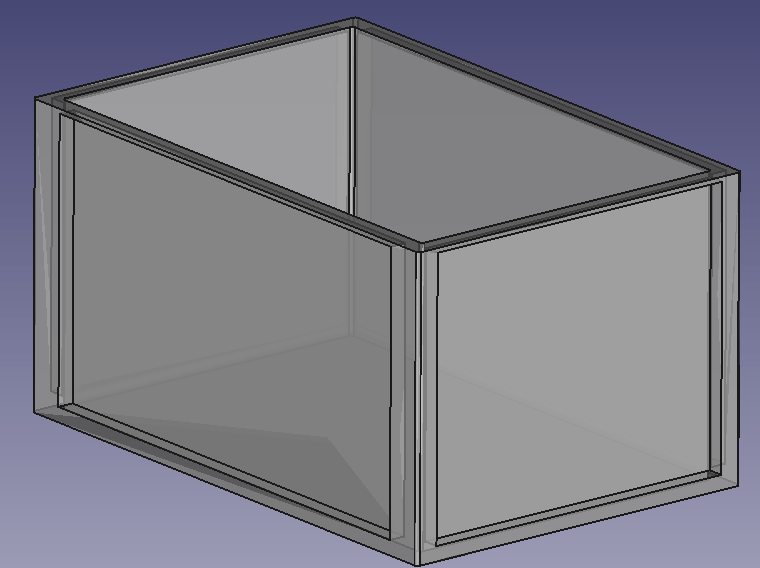
So, I started with some sketches in FreeCAD and came up with the follwoing layout.
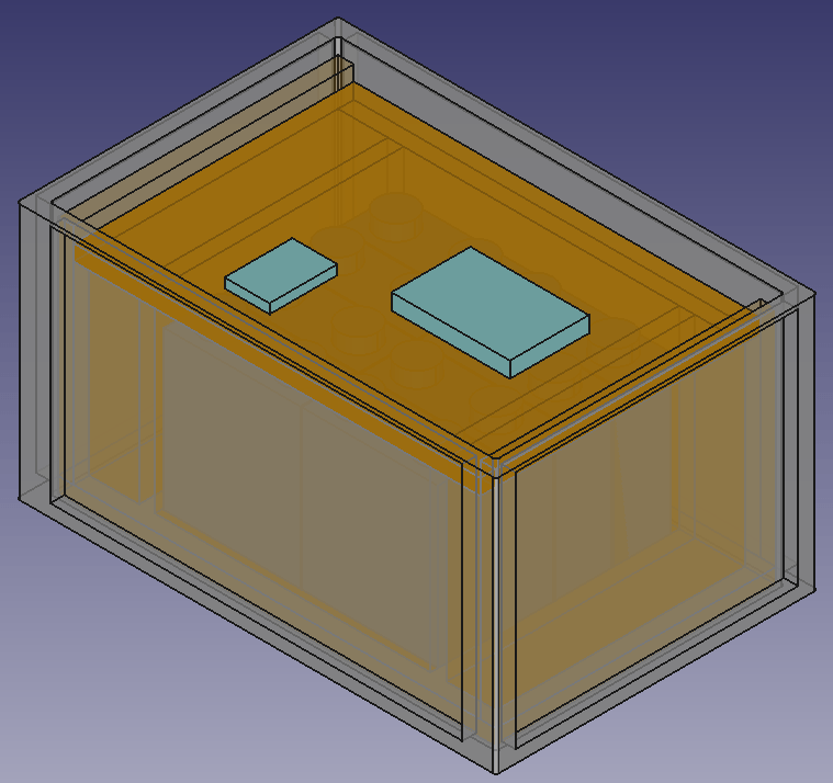
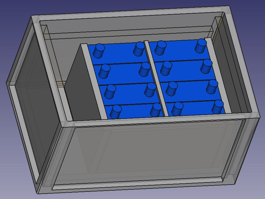
It should be possible to fit 8 EVE LF280K batteries in a 600mm x 400mm x 325mm RAKO box and still have space for the electronic components. Inside the plastic box there is a wooden structure, so the weight of the batteries is better balanced (the plastic floor might like this).
Batteries will be insulated against each other and fitted with sponge strip. Internal cabling will be fed through the lid where the BMS is mounted on. Cables to the outside (VE.Bus, 2*35mm2 DC, 2* 3-core AC) will be fed through the side wall.
Empty utz RAKO box 600mm x 400mm x 325mmBox with batteries and electronic components on topView of frame with cells inside box
BMS Cabling
I am going to use a 150A JK-BMS for the battery which comes with 2 pairs of 7 AWG wiring (approx. 10.5mm2 per wire). As I am going to have a mximum current of 150A (at 20V; or 117A at 25.6V) this will result in a voltage drop between 0.1% and 0.2% on the BMS cable. For the rest of the cable to the battery I will use a 50mm2 that results in an additional max 1% of voltage drop. The actual connection to the batter will be done via an Anderson SB 175 connector.
The individual BMS cell wires will be fed through a WAGO TOPJOB S 3-conductor through terminal block (with a separate fuse) (or I use a WAGO 2-conductor fuse terminal block – don’t know yet). With this I can easily connect and disconnect the individual wires from/to the cells. And with the 3-conductor terminal block if needed, I can later add an additional balancer to the system without having to rewire the cells either.
The cells will be wired in a regular 8s cconfiguration to the BMS. Both voltage sensors will be placed in the middle of the batteries.
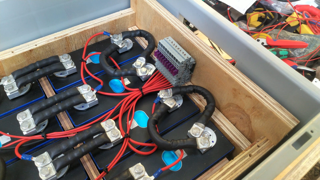
Bus bars
My Eve LF280K cells have 2 M6 thread for each pole. The bus bars that came with the cells (cross section is 2mm * 20mm) were not flexible and only suitable for connecting the poles on the long sides. However, with my 8s configuration, I need 4 connections on the short side and 3 connections on the long side of the cells.
So, I created my own bus bars with the help of 2* 35mm2 DIN46235 M6 cable lugs per connection.
Dimensions: short side 30mm + 29mm; long side 30mm + 80mm (cutting at 30mm for the cable lugs to be crimped).
The Build
So, I with this information I started the actual build. And certainly I made some adjustments to the layout. This is what it looks like:
Case with all the cells on one side
As you can see, I moved the batteries to one side. With that I have more space on one end to install a MCB and leave room for cables.
Updated drawing with cells on one sideWago fused terminal blocks for connecting the indivisual cell wires
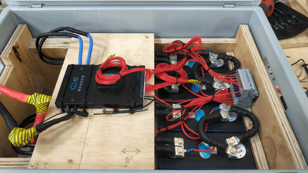
Connection of the BMS to the cellsCase with cells covered
The BMS rests on a board that can be fixed to the side walls. I intentionally left some space between both boards to have room for the temperature sensors. On the right hand side, we see the BMS wires connected to the terminals. With this it is easy to see which cable goes where. I could have cut the BMS wires. Maybe I will do this later.
As the DC cables were quite stiff, I used a screw to support a 90° angle on the cable going out of the box. The screws are fitted with electrical insulation wire. Let’s see how long this holds up.
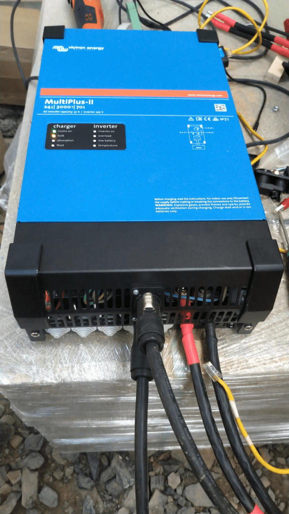
Victron MultiPlus-II 24/3000/70-32 with Neutrik connectors
The inverter now has Neutrik panel connectors. I used a 24mm and 29mm hole saw for this. With this I do not have AC cables hanging out of the inverter. The connectors are rated for 16A (VDE) or 20A (UL). I set the maximum current on the inverter settings (as the inverter supports up to 32A which is beyond the capabilities of the socket).
Of course, the DC cable is still present. Maybe I can install a socket for that as well.
Inverter with battery
Above you see the “final” case. The battery is connected via Anderson SB 175 to the inverter. The battery cables fits into the case when not in use.
Not seen on the picture. The inverter has been fitted with a Siemens 16A RCBO for AC out. And inside the case is a non-polarised Thomzn 125A DC MCB.
The BMS charge and discharge current is set to 125A (though the inverter only supports up to 70A, and in reality only seldomly charge with more than 63A).
The Specs
With this inverter/battery duo, I have a system with a nominal power of 7168Wh that can deliver 2400W of constant power (below the 0.5C rating of 140A). Down to a cell voltage of 3V I can make use of the full power (then running at 125A). As the current minimum cell voltage is configured to 2.55V I always have a minimum power of 2550VA (or 2040W). But in reality I have never seen all the cells at the minimum voltage at the same time.
The case weighs around 51+kg and the inverter is around 20kg.
The maximum charge current of 70A @24V result in a maximum charge power of 1680W. So theoretically it takes slightly over 4h to fully charge the battery. In reality we can expect the battery to be charged around 20% per hour. A real life test shows that within 3h we can charge from 20% to 85%.
The Aftermath
What went well, what went wrong? Here are some of my thoughts:
The case looks and feels solid when lifted. So I really think the weight will not by a problem, though the RAKO box is not certified for that weight. I think, I could have used even thinner plywood and that would have saved some additional space.
Moving the cells to the right made more space on the other side, so I was able to fit the DC cable with the Anderson plug into the case as well (in addition to a MCB).
Creating the bus bars was relatively easy. The cable is still quite stiff. And the longer bus bars bend over the edges. That is why I had to add an extra piece of board to the sides.
The JK BMS wires are very fine strained and hard to get into the lugs (it literally took me over an hour to connect the 4 wires).
The addition to the fused terminal blocks makes the cabling much cleaner. But the WAGO terminals are not cheap.
Unfortunately, with my JK BMS the cables are soldered to the BMS and cannot be replaced. I think 2* 7 AWG is relatively small/thin. I would have preferred 2* 35mm2 (as for the bus bars). With the new JK BMS model there is the option to connect my own cable to the BMS.
This version of the BMS comes with a power button, making it much easier to turn it on than before. No need for a DC power source with higher voltage than the cells.
Fitting the cells into the case (with some compression) was easier than I thought. I used some insulation board between the rubber and the board to push it between the frame and the cells.
I actually do not use the RS485 option for this standalone installation. The BMS seems to take care of the the charge and discharge currents. And if I have really have to know the SOC, I connect via bluetooth to the BMS directly. And I only use the VE.BUS connection with the VictronConnect App when I want to change or limit the AC input current. For this I use the VE.BUS bluetooth dongle.
Having the Neutrik connectors makes it much easier to disconnect the inverter when moving.
Regarding the Neutrik panels on the inverter. I could not fit them in the holes where the AC wirng would normally go through, as the cable clamps were in the way. So I had to use the space between the ventilation slots. It is quite fiddly to get them screwed onto the cover. I used a 24mm and 29mm hole saw with M3 x 20mm hex bolts and M3 hex nuts for it.
The integrated RCBO saves me from having a separate elecitrical panel.
Maybe I change the DC connectors to Amphenol sockets as the SB175 is quite bulky. (update on this: probably not; they are quite expensive and only have 50+ connection cycles guaranteed; plus, it is not specified if they can be switched under load)
The cost
Here is a rough estimate of the accrued cost for this build:
Estimate for the material used for this build
If I only count the cost for the case (excluding cells, inverter, BMS) I come up with approx. 400CHF/450USD/350GBP/400EUR. So it seems, that I could have bought a prebuilt case for nearly the same amount of money, right? True. But … with this case, I have the exact dimensions that I want and with much less weight. And with the exact components I want. Plus, I can repair (if needed) everything by myself, as I completely know how it was built.
Let’s see what I will change on the next case I build.
Updates
Here are some hints and thoughts that arose after I wrote the article.
Getting the cells into place I used a 12mm marina plywood with an extra sheet of insulation board, so the board could “slide” (be pushed) between the frame and the cell. I used a planer with a depth of 0.5mm to cut away just as much so I could just firmly squeeze it in.
Frame and any wooden part in general It is a good idea to grind the surface of the wood facing the cells to remove any pieces sticking out that could damage the very thin insulation of the cells.
Insulation boards At first, I cut the insulation boards from a 250mm x 500mm board. I found it the easiest way to use a drawing pin to mark the cut and then bend it bothways. But this means we have to do 5 cuts for getting 3 boards – that takes time. So, I now have precut 170mm x 200mm insulation board with rounded corners. Much easier to handle.
Fixing the M6 bolts to the contacts I used an insulated torque ratchet wrench (4Nm) to tighten the bolts to the contact.
For the cable lugs I used Klauke M6 35mm and 16mm DIN 46235 cable compression lugs.
For the cell voltage sense cable I used 2.5mm wires (I know, 1.5mm would have been more than enough, but it was the only wire size I had). The JK-BMS supplied voltage sense cables were fitted with uninsulated ferrules, so they would fit into the WAGO 2002-1681 terminal fuse blocks.
Regarding cost The other day, I saw Pylon US3000 3.55kWh Lithium Battery being sold at CCL Components for 860.06GBP (excl. VAT). This includes a 19″ rack metal case, a BMS, connectivity and the cells and equates to roughly 269 GBP/kWh. Quite a bargain! Why making your own battery (case) any more?
I will replace the 24s BMS with an 8s version so I can use 35mm2 cable all along. Plus, I will use two pairs of 35mm2 cables from the inverter to the battery. That also means, I will have 2 separate 63A DC MCBs instead of a single 125A MCB.
Cutting the plywood
I found web site that offers help in cutting rectangles in a more efficient way that I could come up with: Cut list optimiser. The board for the case could be cut like in the image shown below.
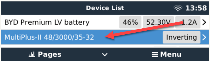
The other day, I connected my BYD Battery-Box Premium LVS 8.0 to a Victron MultiPlus-II 48/3000/35-32. Here are the steps I took to do it and some errors I ran into.
The Battery-Box needs to communicate via CAN with the inverter. And as Victron inverters do not come with a CAN port by default (unless you go for a MultiPlus-II GX or EasySolar-II GX) we need a GX device. Originally, I wanted to use my Victron Cerbo GX for that, but since we moved into the caravan the device is gone missing. Luckily last year, I supplied myself with a couple of Raspberry Pis (at least model 3and 4 are supported) that could run a Venus OS and act as a GX device. And as I was not the first one doing that, I thought it would be just too easy – well, it was easy after I did everything right.
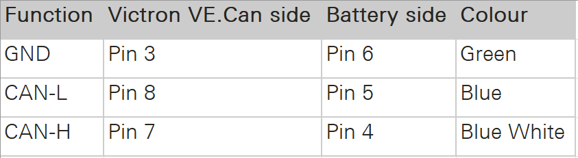
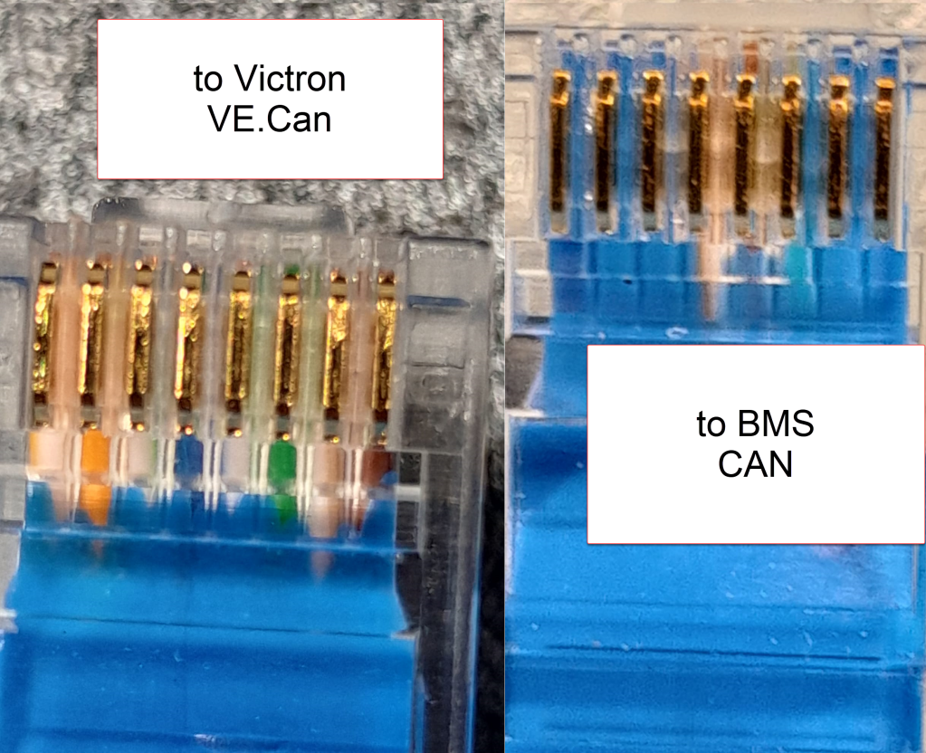
Normally, Victron requests to use a VE.Can to CAN-bus BMS Type A cable to connect to a BYD battery. This is actually an ordinary CAT 5e network cable with RJ45 connectors where only the relevant CAN pins (and GND) are connected.
In order to screw the wires to the CAN hat terminal, I used uninsulated ferrules. Otherwise the Cat 5e wires would have been too soft and light for the terminal.
Installing Venus OS on the Raspberry PI 4
For the Raspberry PI 4, I followed the documentation and installed the standard (and not the large) image. At that time, v2.93 was the newest version (see here for directory of all versions). I uncompressed it and used Win32DiskImager to write the OS to a MicroSD card (all done on a Microsoft Surface Go2 running Windows 11).
Note1: at first, I did the install with a Raspberry Pi 3 Model B V1.2 which also worked fine. However, the CAN device on the Victron UI then did not show any packets but worked without problem.
Note2: The Raspberry Pi 4 is a model B Rev. 1.5 (I mention this, as I saw comments that indicated that there might be a difference between different revision from 1.2 onwards).
Note3: I activated the “Mobile” tile to be able to change the charge current via the overview screen.
The CAN driver then had to be installed separately. As I did not have direct internet access from the Pi, I used the offline install method with a USB memory stick.
As written in the documentation, I copied the compressed installation files as venus-data.tar.gz to the root of the USB drive and restarted the Pi. To verify the automatic installation was successful check if there is a new menu item Package manager at the end of the Settings list. If not visible check if you can find SetupHelper in /data. You can always manually copy it from the SDCard (use mount to see where the card is mounted) and then run setup yourself. I did a reboot after every package.
New menu item in Settings after installation of SetupHelper
Same procedure here. Copying the compressed installation files to the SDCard as /venus-data.tar.gz. Then run the package installation manually if for whatever reason the automatic install does not succeed. See below what the package manager should look like after the installation of both packages.
List of active packages in Package manager
Installing the driver
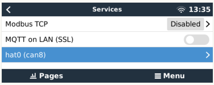
Configuring the driver had to be done from the terminal. There was a minor issue for me which I did not get right the first time. When asked to install an interface via the i option I actually had to type in a hat. I named the device hat0 and after the reboot it showed up as hat0 (can8) can8 spi0.0. In my case it was the “Waveshare 1-channel CANbus Hat 12 MHz crystal” (check the imprint on the silver part on the hat to see the crystal speed).
Configuring CAN bus
There is really not much to configure. The only option under “Services” is to set the communication speed which is 500kB/s for BYD. If the CAN adapter does not show up make sure the correct type has been selected in VeCanSetup. For me it just worked out of the box.
CAN hat showing up in ServicesSetting the CAN speed for BYD Battery-Box BMUConfigured CAN bus
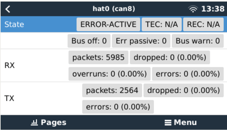
Before the BMS is connected the CAN should show up as ERROR-PASSIVE. As soon as the communcîcation worked it changed to ERROR-ACTIVE.
CAN bus ERROR-ACTIVE with actual traffic
Note: When I tried with the v2.93 on the Raspberry Pi 3 the RX/TX counters were always empty (but nevertheless worked). Via ifconfig the packets were correctly shown. But with the Pi 4 traffic was shown on the UI right from the start.
CAN bus traffic via ifconfig
I did not connect the CAN cable at that point but configured the Battery-Box and the inverter first.
Commissioning the inverter
I used a USB MK3 adapter with an RJ45 Cat 5e cable connected to the VE.Bus of the inverter to configure the MultiPlus.
I used VEConfigure 3 and VictronConnect (to be able to configure via VictronConnect I had to use the zzz password to get out of the read-only mode).
First, I updated the firmware of the MultiPlus via VictronConnect and then continued with VeConfig.
Basically, I set the inverter to off-grid and did not enter a country code. For the battery type I selected “Lithium Iron Phosphate” and accepted the default settings. I set the “AC current limit” to a maximum of 20A (the maximum my generator could handle) and activated the option to have it overruled by “Remote” (which can also be done via the GX Remote Console or VictronConnect).
Setting AC current limit via GX remote console
I also activated DVCC to later have the BMS tell the inverter when to charge and how to discharge. This was pretty much it. So I connected the MultiPlus via the VE.Bus and the MK3 cable to the Raspberry where it showed up instantly.
Inverter shows up after connecting VE.Bus to the Raspberry via MK3
Commissioning the Battery-Box
After assembling the battery which conisted of only stacking both battery modules on top of each other followed by the PDU on the very top I connected the BMU via the grey RJ45 to the PDU. After turning on the top most battery the BMU started as well and I was able to connecto to the WiFi of the BMU from the BeConnect app (Android or Windows both worked for me, the latter actually showed more information).
Via the app I pre-downloaded a current firmware and after switching to the BYD access point I applied the firmware (actually two different firmwares). After some waiting the new firmware had been applied and I could configure the basic settings: inverter manufacturer, number of battery modules.
At this stage I connected the 35mm2 cables from the battery to the inverter. I bought the cable preconfigured with the battery. And I used a Littelfuse JLLN-125X (class T) as a fuse between both devices.
Connecting the battery to the Venus OS
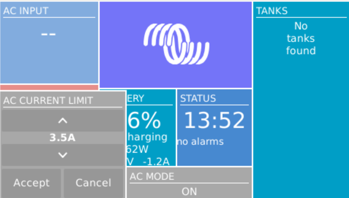
And then I connected the BMU to the GX. After some seconds, the inverter clicked and started charging. Essentially, DVCC turns on automatically (even if turned off before) as soon as the CAN communication is established.
In the GX overview the battery appeared and gave some additional information (see next section for details). All parameters between battery and inverter were exchanged automatically.
Things I noted
The battery turns itself off after a while when no communication via CAN is possible. This behaviour is described somewhere in the BYD manuals.
Charging the battery does not work when no CAN connection can be established. The inverter stays in “Absorption” mode with a current of 0A.
A more detailed description of the pin layout can be found on the BYD manuals. See images below.
The GND pin is not required for communication between the BMU and the VE.Can GX. Only BLUE for CAN-H and BLUE-WHITE for CAN-L are going into the CAN hat.
In addition to the official web site bydbatterybox.com the web site eft-systems.de provides additional information and downloadable documentation.
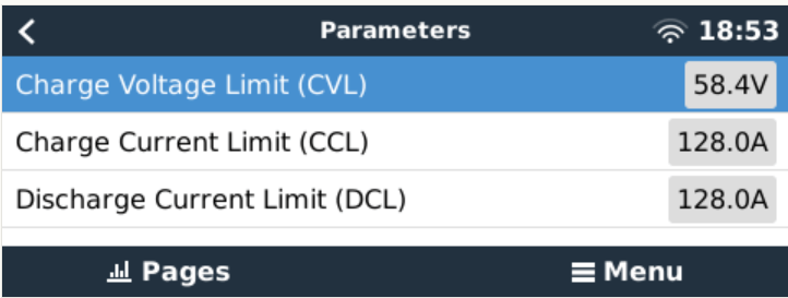
When charging the Battery-Box for the first time, I eventually reached a 100% SOC. Until that point the charge current stayed nearly constant at around 30A (Bulk). It decreased to around 1.2A and the inverter turned to “Absorption” but never stopped charging. At some point one of the cells reached a voltage of over 3.7V which resulted in a warning on the GX. Nevertheless, charging continued. I manually switched off the charger after the second time I received a warning due to high cell voltage. I would have expected to have the inverter automatically stop charging at a 100% SOC. Maybe the BMS only measures the charge voltage limit (CVL) which is defined as 58.4V and not the individual cells?
The cells in a battery were not really well balanced (delta >= 100mV). I would have expected a better balancing. Actually, I do not know if the BMS has a balancer at all. I could not find anything in the documentation.
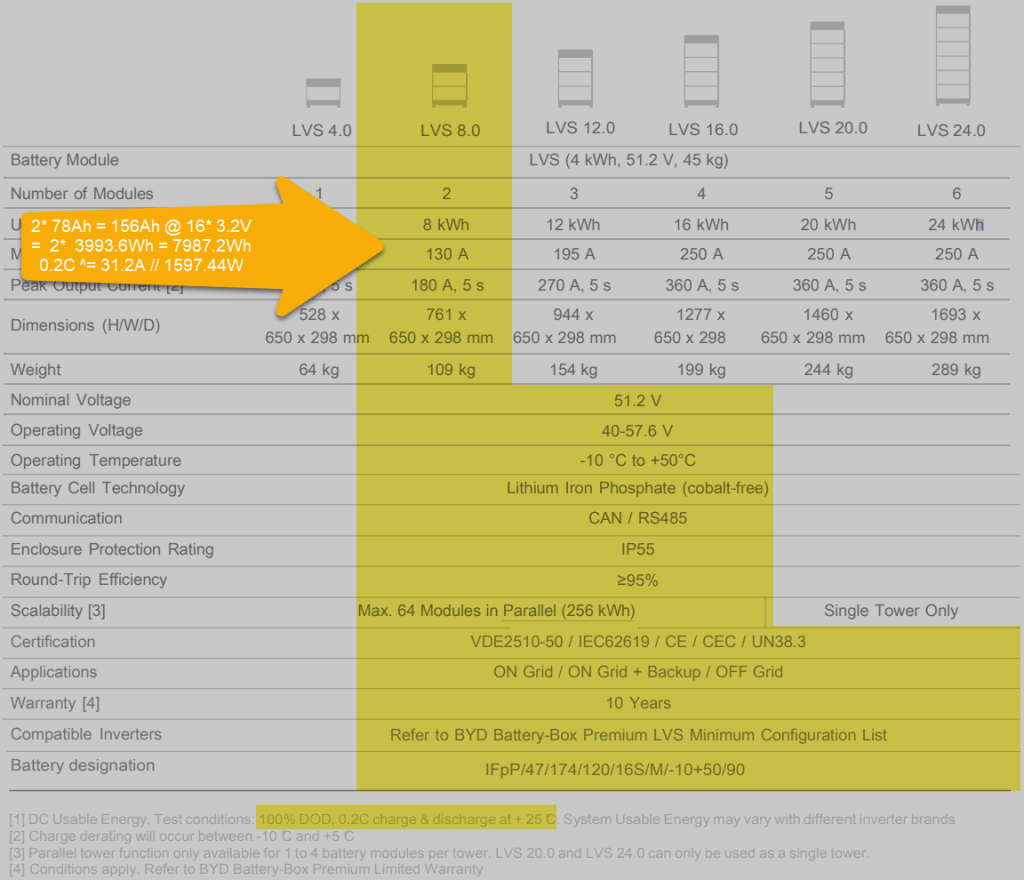
Each LVS 4.0 has a capacity of 78Ah @ 51.2V = 3993.6Wh. The GX shows this information in the “Details” item within the battery. I could not find this information in the manual.
The BYD manuals state, that the lifetime of the battery can only be achieved at 0.2C, which limits a single LVS 4.0 to 798.72W (or 1597.44W for a LVS 8.0) – this is a ridiculous small amount.
Charge current was initially restricted to 38.4A by the battery, only after a day or so, the charge (CCL) and discharge current (DCL) went up to 128A. In my case the inverter only support 35A max, so no issue with that.
Startup sequence Start top-most battery first by pressing the power button for a couple of seconds; then start the BMU if not automatically started; next start the inverter; then start the GX (in my case currently on the AC side).
Shutdown sequence Turn off the inverter; turn off the BMU; turn off the individual batteries (keep buttons pressed for a couple of seconds); GX turns off automatically.
Adding a CAN hat in VeCanSetup needs to be entered literally as a hat.
Though I set the AC charge current to 20A the inverter only drew 16A at most.
The WiFi of the BMU cannot be changed, nor the password.
BYD RS485 CAN pin layout, taken from the BYD BMU maualBYD to Victron CAN pin layout, taken from the BYD BMU manualBYD Battery-Box voltage and charge limitsSpecification of BYD LVS 8.0, taken from the BYD manuals
Future improvements
I want to connect the Raspberry to the DC side with a 48V/12V step-down converter and a 12V to USB-C adapter. Inbetween I want to add a power bank, so the GX can be configured even if all power sources are down.
Replace the CAN hat with a USB CAN adapter
Strengthen the connection of the CAN wire to the CAN adapter
All in all, the installation was straightforward. A couple of uncertainties are probably normal when doing this the first time. I would have expected more documentation (articles, videos) for this to be around. But I could not find anything for a BYD, Victron, VenusOS via Raspberry setup. Maybe others are only using a Cerbo GX?
The batteries are well built (all IP55) but extremely bulky and pricey. With around 400 CHF per KW this is more than 300% of regular LiFePO4 cells. But nevermind, lead and delivery times are in the magnitude of months.
I would have liked the BMU to be integratable into one of the PDU boxes. Now it is just hanging around separately.
Would I buy another Battery-Box? Probably not – too pricey. But good for starters. Plug and play when used with Victron and a Cerbo GX.
The Caravan we got last year did not come with an inverter, so getting coffee in the morning or running a microwave was only possible when our main generator was running. And the installed battery for 12V support had a rather small capacity. This was clear to us from the beginning, as we eventually wanted to connect the Caravan to our EVE 280Ah cells.
But since we got our Starlink internet and our router did not seem to run easily on DC power, we needed -in addition to the temporary morning AC coffee spike – a more permanent AC solution.
Of course, first I updated the firmware of the inverter and configured it work with the battery:
Setting the AC input to 16A
Setting the battery type to LiFePO4
Setting the charge current to 70A (which is over the recommend amount of 50A, but see below for details)
As I did not want to connect a Cerbo GX to the system, I just used the VictronConnect App. Maybe I add a VE.Bus Smart dongle later on, or I connect some GX nevertheless. Who knows … Until now, it needs a wired connection to the inverter to see its status.
After powering on the generator, I confirmed everything was roughly working as expected. During the first run, the SOC was shown as 100% though the BMS of the battery internal saw it differently. In addition, the reported Amps and temperature were seen differently, as well. So, even that I set the inverter over the recommended maximum of 50A for the battery, the actual charge power was never much higher than the actual maximum).
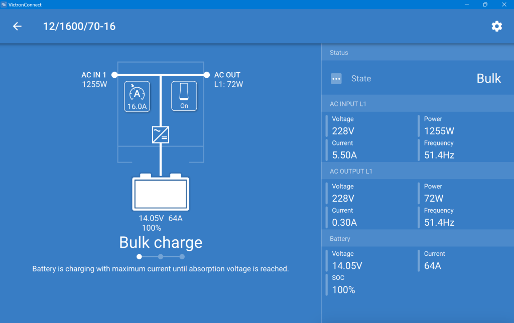
This is what the inverter saw (100% SOC, 14.05V DC cell voltage, charging at 64A):
MultiPlus charging the Liontron battery via the generator
And this is, what the Liontron BMS reported (76% SOC, 13.8V DC cell voltage, charging at 55.5A):
The SOC as seen by the Liontron battery BMS
In the end, the BMS stopped charging when it thought its batteries were full. And the inverter did not complain. However, I noticed that the cells were really not in balance (with a delta of 200mV between the lowest and highest voltage).
Discharging was ok, as well. However, I soon realised that the 100A discharge current could not be achived in my setup. The inverter tried to draw power and the BMS cut off with a “Discharge over-current” (OCD). SO, still no coffee via our Nespresso machine (and no microwave either, for that matter).
So, what is the take away of all this?
It works and now, I can run the Internet all day.
All in all, it is a relatively simple and quick setup.
The Liontron battery does somehow not live up to its specs (and yes, I know the battery could be a size bigger for what I want to achieve; but I did not want to buy an additional battery for this temporary solution).
It is way cheaper and more flexible than to buy this “off the shelf”.
Maybe, I add a Victron SmartShunt to get a more accurate SOC reporting (as I do not see any other way to integrate the BMS with the inverter).
Charging of the battery is quite fast when running the generator.