I never actually measured the difference in internal resistance of the ones we built and some we got with our EVE LF280K cells. Time to correct this …
The flexible busbars delivered with our cells have approximately these dimensions: 105mm * 20mm * 2mm. This should give us a surface area of 40mm2 and an ideal internal resistance of around 0.045mOhm (according to some online calculators).
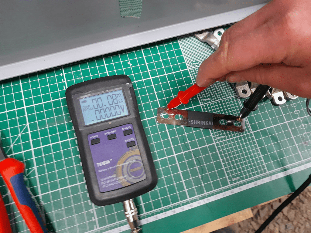
When measuring this with our trusty and highly precise TR1035+ the result displayed is 0.08mOhm.
Pre-built busbars 105mm * 20mm * 2mm
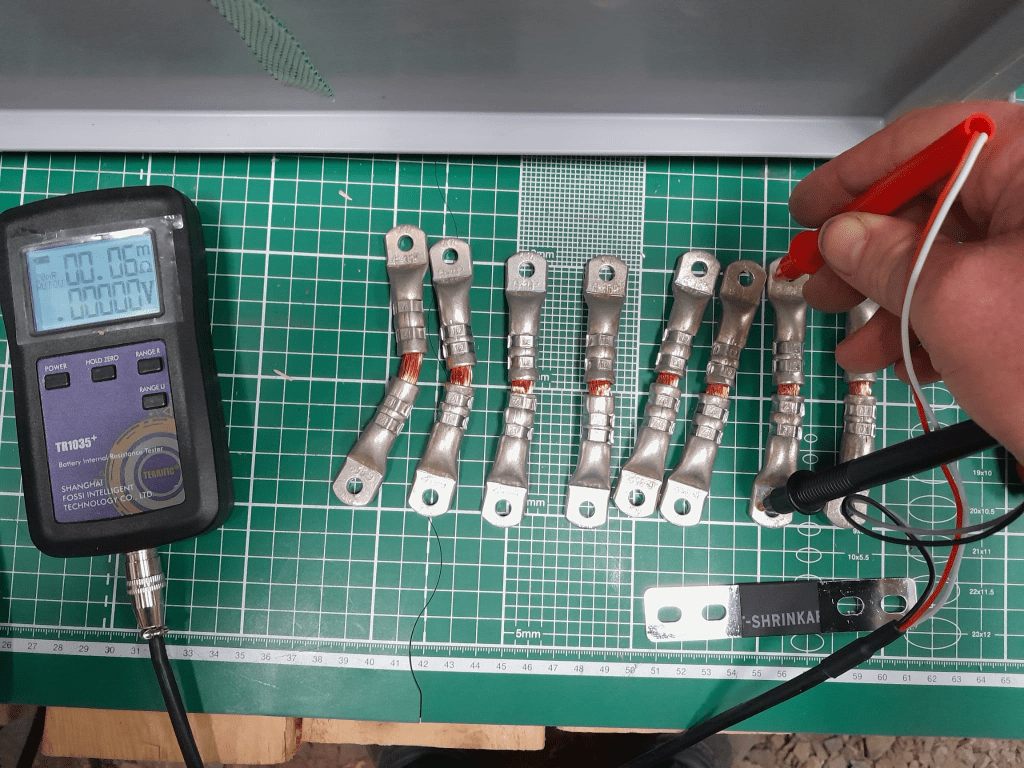
The Klauke version which comes with tinned copper lugs gives us a reading of 0.06mOhm – despite the smaller cross-section of 35mm2. The ideal internal resistance of the copper wire could be expected to be around 0.051mOhm (according to some other online calculator), so we are much closer to the measured value.
Custom busbar 105mm * 35mm2
The display error of the TR1035+ is expected to be similar as the measured range of both busbars is quite similar. There is certainly quite an amount of uncertainty (not only due to the maximum resolution of 10uOhm) to it. But it is interesting to see that the resistance of the custom busbars seems to be lower despite its smaller cross-section – while being better insulated (not seen on the picture) and more flexible at the same time (as it can be bent in more directions).
Producing these custom busbars is certainly more expensive (a single lug costs around 1.17GBP or 1.27CHF) and involves more manual and time consuming labour. However, it is quite easy to double them and/or increase its cross-section to up to 70mm2 per wire (when using multi-stranded DIN EN 60228 conductors).
So, this is it for today with fascinating facts about busbars for LiFePO4 cells.
For this build, I planed all the boards after cutting, before putting in the cells. With this, I hoped to minimise the chance of any particles on the board damaging the cell insulation.
And for the small board at the short side of the case, I did also use 20mm plywood, but planed it several times until it I could just slide it in.
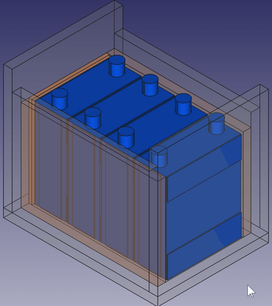
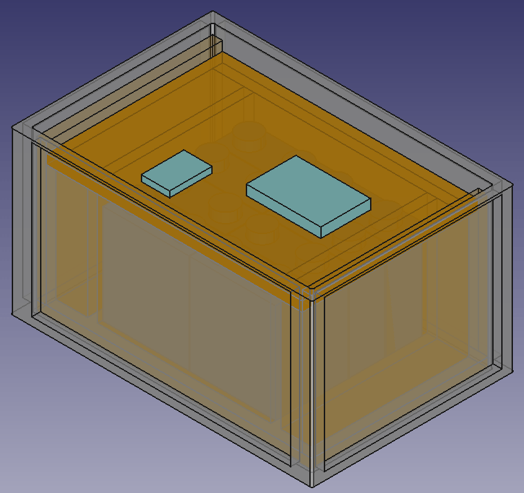
This is how the wooden case looks with the cells and insulation boards (shown in red):
Top view: battery cells with depicted insulation boards (shown in red)
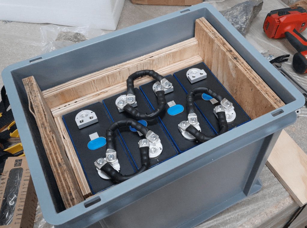
Note: when using a JK-BMS I found it important to have the main negative connection point on the upper left (or lower right). Only with this orientation it was (relatively) easy to connect the cell to the BMS.
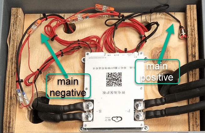
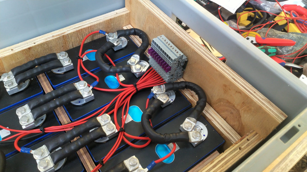
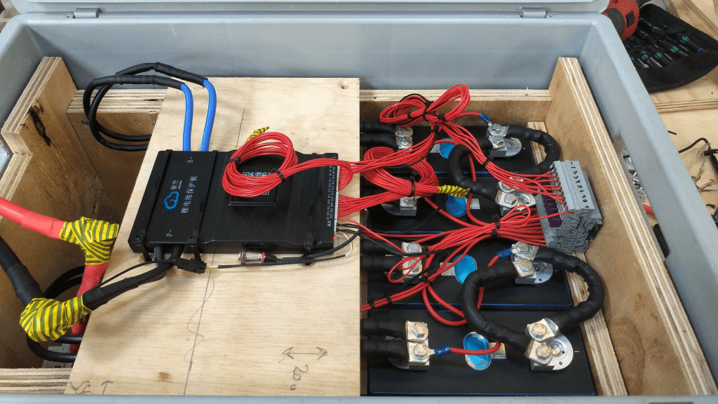
BMS connected to cells
It needed some fiddling to get the main negative cable pair to the BMS and the main positive cable pair out of the frame, as we can see from the image above.
The connection to the individual cells are fed through WAGO 221-2411 2 conductor inline splicing connectors. The holes into the top board were done with a forstner bit and a jigsaw. This version of the BMS can be fixed with four screws to the board (so no need for wire straps as with the 24s version).
Again, instead of a display I just used the pluggable power button that is connected to the display port of the BMS to power on and off the device.
In the end, I added Anderson SB175 connectors and 1383 (2AWG) contacts to both pairs and connected them to the inverter.
cell contacts were secured with M6 serrated washers and M6 16mm steel bolts;
BMS threads B- and P- were secured with M6 lock nuts to M6 16mm steel bolts (with the bolt upside down);
cell wires from the BMS were fitted with uninsulated ferrules;
cell wires on the positive cell poles were fitted with ring lugs and a 2.5mm2 hookup wire;
I added handles to the SB175 connectors to facilitate disconnecting the cable pairs;
I added dust covers to the SB175 connectors;
all compression cable lugs and the SB175 were crimped with a Hilti NUN54-22;
all cable lug connections and Sb175 were heat shrinked;
I added 2*35mm2 cable pairs with SB175 connectors to the inverter by replacing the existing 35mm2 welding cable with M8 lugs (you still need M8 lugs on the inverter positive and negative terminals).
Things to improve next time
Mount the SB175 connectors to the outside of the container With this the lid can be closed and the cables and BMS are better protected against pulling;
add 3A inline fuses to the cell wires;
use 45° angled cable lugs for main positive and main negative to make it easier to get the wires routed outside the container;
feed an additional wire pair for the voltage sensor from the main positive outside the container to be able to connect it to the inverter (but I am not too sure about this, as I think the voltage drop on the 2*35mm2 connection is neglectable – it might better to add a temperatur sensor to the main positive):
add a Victron MK-3 USB-C interface with RJ-45 cable into the case (to be able to restrict AC power on the inverter).
What did it cost?
Cost calculation for the 4s battery including case and inverter
Summary
This case is not as complete as the 8s version – due to its form factor. Neither the inverter has an RCBO nor the battery has a DC MCB. This has to be added separately (incurring additional cost and space). As written above, the 4s version is more like a traditional battery. However, the form factor is quite compelling; 3.5kWh in 400mm x 300mm x 325mm case. Especially in combination with the compact edition of the Victron MultiPlus. And the cost (as always without labour) is very reasonable, as well.
The inverter delivers 1200W constant power – in my opinion, enough for a small and mobile electricity build. Runnig a Krups Inissia Nespresso machine is not a problem, and boiling water with our 1000W immersion heater neither. Worst case, you could also run a 300W infrared panel heater for more than 11 hours.
One drawback of the inverter is probably the relatively small charger. With 70A at 12V it can only charge the battery with around 840W. This is certainly not the problem of the battery which would support charging up to 1344W.
In one of our previous articles, we stated that, due to power, weight and size, we would rather go for a 24V 8s (280Ah) battery configuration instead of 48V 16s.
However, there are relatively few battery cases for 8s battery packs that fit our Eve LF280K cells. And they are pricey! So, instead of spending a 500+ USD per case, I was thinking to repeat what others have done before me: build a case myself. And certainly, I took inspiration from variousothers and commercialkits.
So first, here are my requirements:
Case must fit 8 EVE LF280K cells including all electronics and cabling such as BMS, MCB, GX.
Battery must be pluggable to the inverter via Anderson SB 175 connector. Check: why not use Amphenol sockets/plugs?
Case must not absorp moisture/liquids that would build up from below.
Case must have no external display or buttons (i.e. solid walls).
Cells must be insulated against each other.
Cells must be fixed to the case so the do not fly around when the box is moved.
Battery status should be readable from the box itself (optional).
The case should be usable independant of any BMS.
Battery is meant to be used 1:1 with a single inverter.
Battery must have an integrated MCB that can also act as a mains switch.
Basic considerations
Zerobrain – LiFePO4 – ALLES und noch viel mehr über Lithium Akkus
Of course, there are more questions to be answered. And I took a lot of inspiration and advice from the discussion above and came to these conclusions:
Fire resistance The cells should not involve themselves in a “chain reaction” if a cell becomes faulty. The critical temperature of the cells starts at around 90°C. If something is really getting sideways, the resin board will not withstand any of that at all. But as the battery case will be contained either within an aluminium container or directly inside in an aluminium box, I will take that as a mitigation (only the brave).
Moving and lifting the cells should have a weight of roughly 8* 5.5kg = 44kg; the 20mm resin board weight roughly 3.34kg (13.67kg/m2); BMS, MCB, cables, lugs etc might add another 3kg; the Rako(R) box has a weight of 2.35kg; resulting in a total weight of 52.69kg – which certainly is over the official limit of 32.5kg to be lifted by a single person – but still doable if one has to. For moving the battery box around I have a trolley where the RAKO box just fits on.
Compression Initially I thought, I would *have* to compress. But according to the above video, it seems the is only needed (or recommended) during the initial charging of the cells (to minimise gas bubble inside the cells). And from then on, it is not *required* for a safe operation of the battery, but instead might contribute to an extended cell life – how much? we do not know. So, I will probably only slightly compress the cells by placing them firmly into the frame inside the box.
Layout
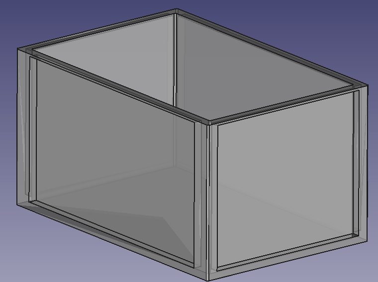
So, I started with some sketches in FreeCAD and came up with the follwoing layout.
It should be possible to fit 8 EVE LF280K batteries in a 600mm x 400mm x 325mm RAKO box and still have space for the electronic components. Inside the plastic box there is a wooden structure, so the weight of the batteries is better balanced (the plastic floor might like this).
Batteries will be insulated against each other and fitted with sponge strip. Internal cabling will be fed through the lid where the BMS is mounted on. Cables to the outside (VE.Bus, 2*35mm2 DC, 2* 3-core AC) will be fed through the side wall.
Empty utz RAKO box 600mm x 400mm x 325mmBox with batteries and electronic components on topView of frame with cells inside box
BMS Cabling
I am going to use a 150A JK-BMS for the battery which comes with 2 pairs of 7 AWG wiring (approx. 10.5mm2 per wire). As I am going to have a mximum current of 150A (at 20V; or 117A at 25.6V) this will result in a voltage drop between 0.1% and 0.2% on the BMS cable. For the rest of the cable to the battery I will use a 50mm2 that results in an additional max 1% of voltage drop. The actual connection to the batter will be done via an Anderson SB 175 connector.
The individual BMS cell wires will be fed through a WAGO TOPJOB S 3-conductor through terminal block (with a separate fuse) (or I use a WAGO 2-conductor fuse terminal block – don’t know yet). With this I can easily connect and disconnect the individual wires from/to the cells. And with the 3-conductor terminal block if needed, I can later add an additional balancer to the system without having to rewire the cells either.
The cells will be wired in a regular 8s cconfiguration to the BMS. Both voltage sensors will be placed in the middle of the batteries.
Bus bars
My Eve LF280K cells have 2 M6 thread for each pole. The bus bars that came with the cells (cross section is 2mm * 20mm) were not flexible and only suitable for connecting the poles on the long sides. However, with my 8s configuration, I need 4 connections on the short side and 3 connections on the long side of the cells.
So, I created my own bus bars with the help of 2* 35mm2 DIN46235 M6 cable lugs per connection.
Dimensions: short side 30mm + 29mm; long side 30mm + 80mm (cutting at 30mm for the cable lugs to be crimped).
The Build
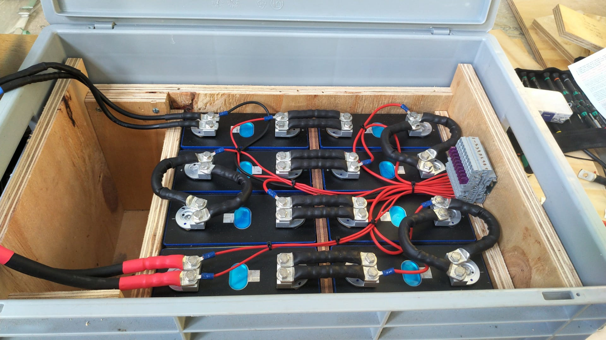
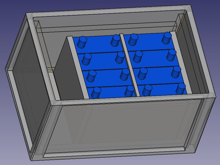
So, I with this information I started the actual build. And certainly I made some adjustments to the layout. This is what it looks like:
Case with all the cells on one side
As you can see, I moved the batteries to one side. With that I have more space on one end to install a MCB and leave room for cables.
Updated drawing with cells on one sideWago fused terminal blocks for connecting the indivisual cell wires
Connection of the BMS to the cellsCase with cells covered
The BMS rests on a board that can be fixed to the side walls. I intentionally left some space between both boards to have room for the temperature sensors. On the right hand side, we see the BMS wires connected to the terminals. With this it is easy to see which cable goes where. I could have cut the BMS wires. Maybe I will do this later.
As the DC cables were quite stiff, I used a screw to support a 90° angle on the cable going out of the box. The screws are fitted with electrical insulation wire. Let’s see how long this holds up.
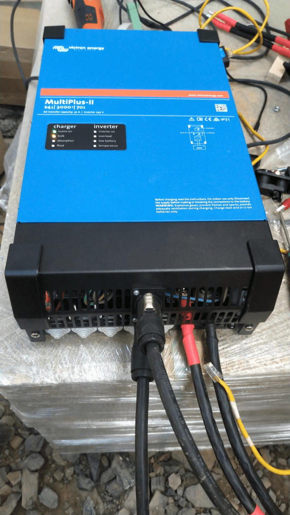
Victron MultiPlus-II 24/3000/70-32 with Neutrik connectors
The inverter now has Neutrik panel connectors. I used a 24mm and 29mm hole saw for this. With this I do not have AC cables hanging out of the inverter. The connectors are rated for 16A (VDE) or 20A (UL). I set the maximum current on the inverter settings (as the inverter supports up to 32A which is beyond the capabilities of the socket).
Of course, the DC cable is still present. Maybe I can install a socket for that as well.
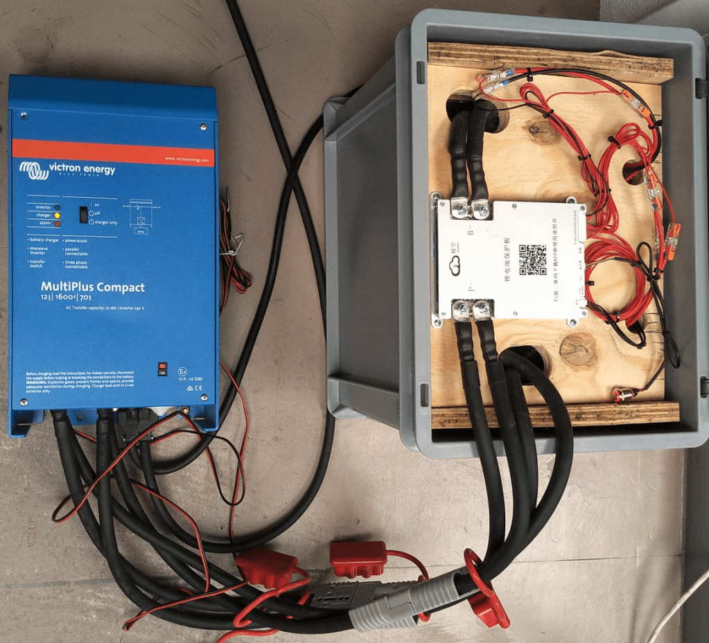
Inverter with battery
Above you see the “final” case. The battery is connected via Anderson SB 175 to the inverter. The battery cables fits into the case when not in use.
Not seen on the picture. The inverter has been fitted with a Siemens 16A RCBO for AC out. And inside the case is a non-polarised Thomzn 125A DC MCB.
The BMS charge and discharge current is set to 125A (though the inverter only supports up to 70A, and in reality only seldomly charge with more than 63A).
The Specs
With this inverter/battery duo, I have a system with a nominal power of 7168Wh that can deliver 2400W of constant power (below the 0.5C rating of 140A). Down to a cell voltage of 3V I can make use of the full power (then running at 125A). As the current minimum cell voltage is configured to 2.55V I always have a minimum power of 2550VA (or 2040W). But in reality I have never seen all the cells at the minimum voltage at the same time.
The case weighs around 51+kg and the inverter is around 20kg.
The maximum charge current of 70A @24V result in a maximum charge power of 1680W. So theoretically it takes slightly over 4h to fully charge the battery. In reality we can expect the battery to be charged around 20% per hour. A real life test shows that within 3h we can charge from 20% to 85%.
The Aftermath
What went well, what went wrong? Here are some of my thoughts:
The case looks and feels solid when lifted. So I really think the weight will not by a problem, though the RAKO box is not certified for that weight. I think, I could have used even thinner plywood and that would have saved some additional space.
Moving the cells to the right made more space on the other side, so I was able to fit the DC cable with the Anderson plug into the case as well (in addition to a MCB).
Creating the bus bars was relatively easy. The cable is still quite stiff. And the longer bus bars bend over the edges. That is why I had to add an extra piece of board to the sides.
The JK BMS wires are very fine strained and hard to get into the lugs (it literally took me over an hour to connect the 4 wires).
The addition to the fused terminal blocks makes the cabling much cleaner. But the WAGO terminals are not cheap.
Unfortunately, with my JK BMS the cables are soldered to the BMS and cannot be replaced. I think 2* 7 AWG is relatively small/thin. I would have preferred 2* 35mm2 (as for the bus bars). With the new JK BMS model there is the option to connect my own cable to the BMS.
This version of the BMS comes with a power button, making it much easier to turn it on than before. No need for a DC power source with higher voltage than the cells.
Fitting the cells into the case (with some compression) was easier than I thought. I used some insulation board between the rubber and the board to push it between the frame and the cells.
I actually do not use the RS485 option for this standalone installation. The BMS seems to take care of the the charge and discharge currents. And if I have really have to know the SOC, I connect via bluetooth to the BMS directly. And I only use the VE.BUS connection with the VictronConnect App when I want to change or limit the AC input current. For this I use the VE.BUS bluetooth dongle.
Having the Neutrik connectors makes it much easier to disconnect the inverter when moving.
Regarding the Neutrik panels on the inverter. I could not fit them in the holes where the AC wirng would normally go through, as the cable clamps were in the way. So I had to use the space between the ventilation slots. It is quite fiddly to get them screwed onto the cover. I used a 24mm and 29mm hole saw with M3 x 20mm hex bolts and M3 hex nuts for it.
The integrated RCBO saves me from having a separate elecitrical panel.
Maybe I change the DC connectors to Amphenol sockets as the SB175 is quite bulky. (update on this: probably not; they are quite expensive and only have 50+ connection cycles guaranteed; plus, it is not specified if they can be switched under load)
The cost
Here is a rough estimate of the accrued cost for this build:
Estimate for the material used for this build
If I only count the cost for the case (excluding cells, inverter, BMS) I come up with approx. 400CHF/450USD/350GBP/400EUR. So it seems, that I could have bought a prebuilt case for nearly the same amount of money, right? True. But … with this case, I have the exact dimensions that I want and with much less weight. And with the exact components I want. Plus, I can repair (if needed) everything by myself, as I completely know how it was built.
Let’s see what I will change on the next case I build.
Updates
Here are some hints and thoughts that arose after I wrote the article.
Getting the cells into place I used a 12mm marina plywood with an extra sheet of insulation board, so the board could “slide” (be pushed) between the frame and the cell. I used a planer with a depth of 0.5mm to cut away just as much so I could just firmly squeeze it in.
Frame and any wooden part in general It is a good idea to grind the surface of the wood facing the cells to remove any pieces sticking out that could damage the very thin insulation of the cells.
Insulation boards At first, I cut the insulation boards from a 250mm x 500mm board. I found it the easiest way to use a drawing pin to mark the cut and then bend it bothways. But this means we have to do 5 cuts for getting 3 boards – that takes time. So, I now have precut 170mm x 200mm insulation board with rounded corners. Much easier to handle.
Fixing the M6 bolts to the contacts I used an insulated torque ratchet wrench (4Nm) to tighten the bolts to the contact.
For the cable lugs I used Klauke M6 35mm and 16mm DIN 46235 cable compression lugs.
For the cell voltage sense cable I used 2.5mm wires (I know, 1.5mm would have been more than enough, but it was the only wire size I had). The JK-BMS supplied voltage sense cables were fitted with uninsulated ferrules, so they would fit into the WAGO 2002-1681 terminal fuse blocks.
Regarding cost The other day, I saw Pylon US3000 3.55kWh Lithium Battery being sold at CCL Components for 860.06GBP (excl. VAT). This includes a 19″ rack metal case, a BMS, connectivity and the cells and equates to roughly 269 GBP/kWh. Quite a bargain! Why making your own battery (case) any more?
I will replace the 24s BMS with an 8s version so I can use 35mm2 cable all along. Plus, I will use two pairs of 35mm2 cables from the inverter to the battery. That also means, I will have 2 separate 63A DC MCBs instead of a single 125A MCB.
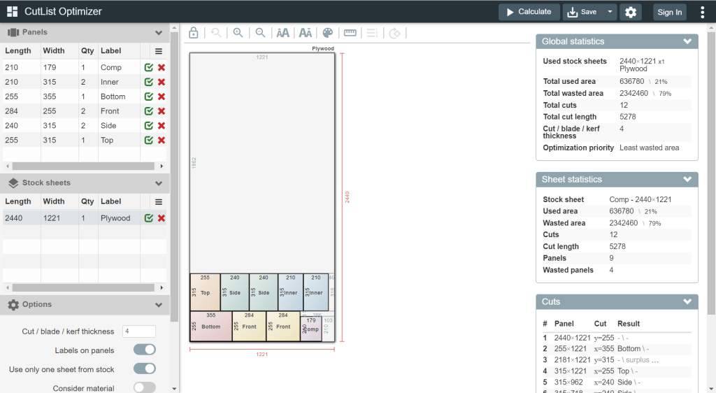
Cutting the plywood
I found web site that offers help in cutting rectangles in a more efficient way that I could come up with: Cut list optimiser. The board for the case could be cut like in the image shown below.