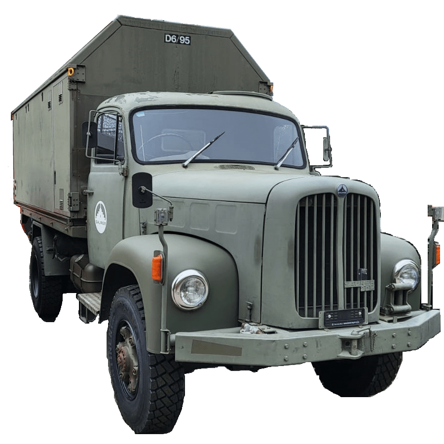
This is sort of a never ending story for me – just as the installation of our workshop container on the truck bed by our trusty mechanic which has been “in the making” since October 2022.
It is clear that we want and need electricity in the container. Just how and how much is not clear yet. In the following, I will consider our rquirements and different apsects and constraints of the electrical installation to hopefully come to a conclusion. This is a rather dry article with a lot of numbers – so beware …
Here is what we know (or at least think we know):
- The truck has a
24Vsystem - Charging any “leisure” batteries via the truck engine on a regular basis does not seem to be a good idea, as the fuel consumption is already
33l/100kmwithout the container (that makes an astonishing8.56mpgin the UK) - It is a
EURO0diesel so we will not be able to get into all the cities (regardless of its problematic weight, length, height and width anyway). - Solar panels are still no real option (most of the time too way up in the North)
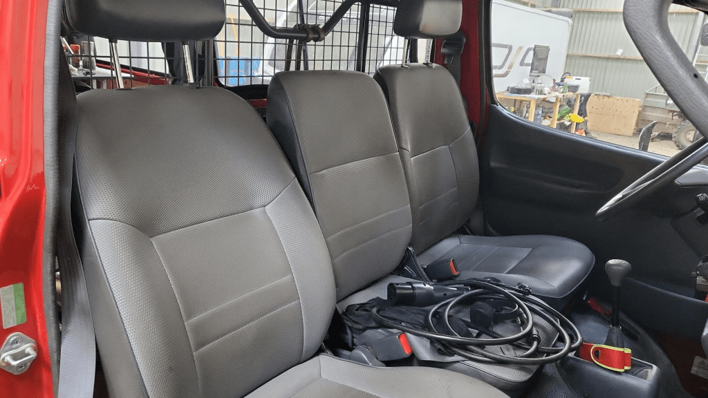
- Charging from an EVSE might not always be possible as most of these EVSEs are for cars and do not have space for trucks
- We want to be able to cook and wash in the vehicle
- We will have a
2kWdiesel heater - We will have a
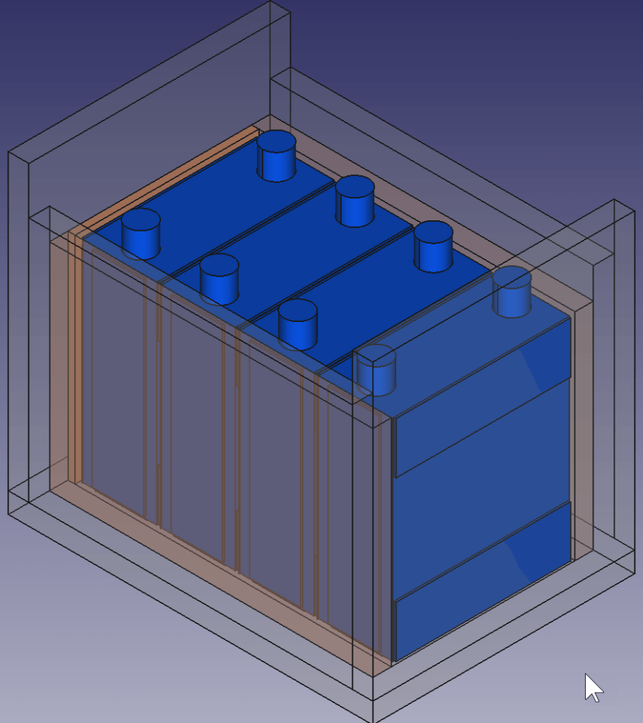
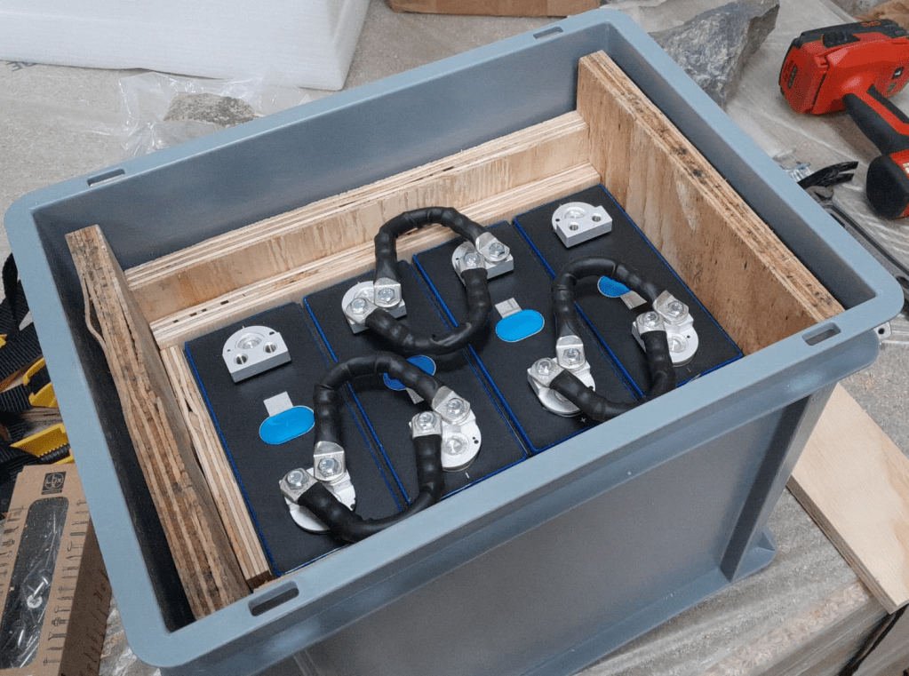
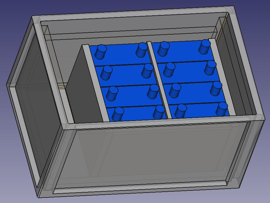
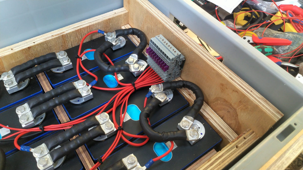
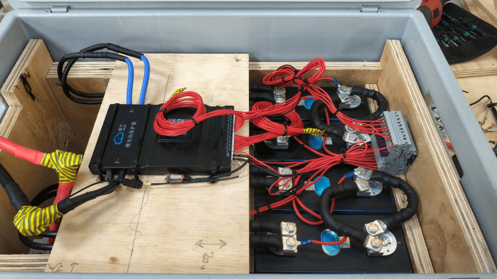
900Wsingle phase petrol generator - We will be using Eve LF280K cells
- The inverter must at least provide
2'250VAor1'800W(concurrently, but not neccessarily on a single phase) - (optional) We would like to have 3-phase power in the container (as the cabling is already in place) – but also we know we would only use it very seldomly (such as for welding, then we need at least
11Aper phase) - We would like to be able to charge
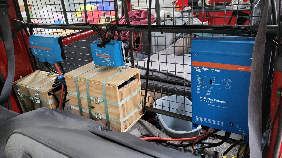
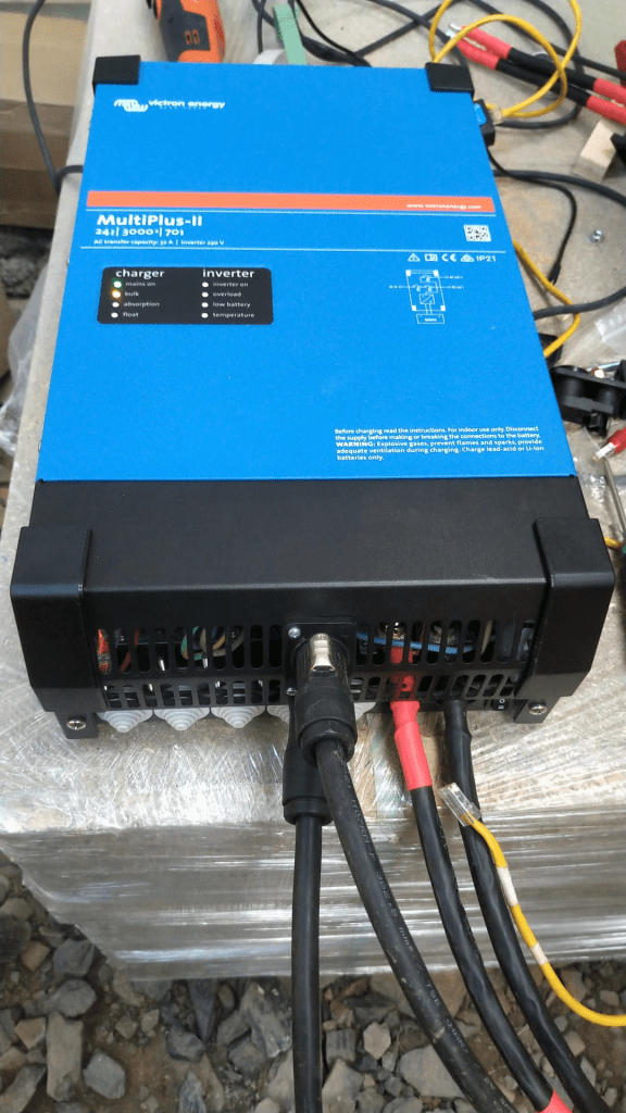
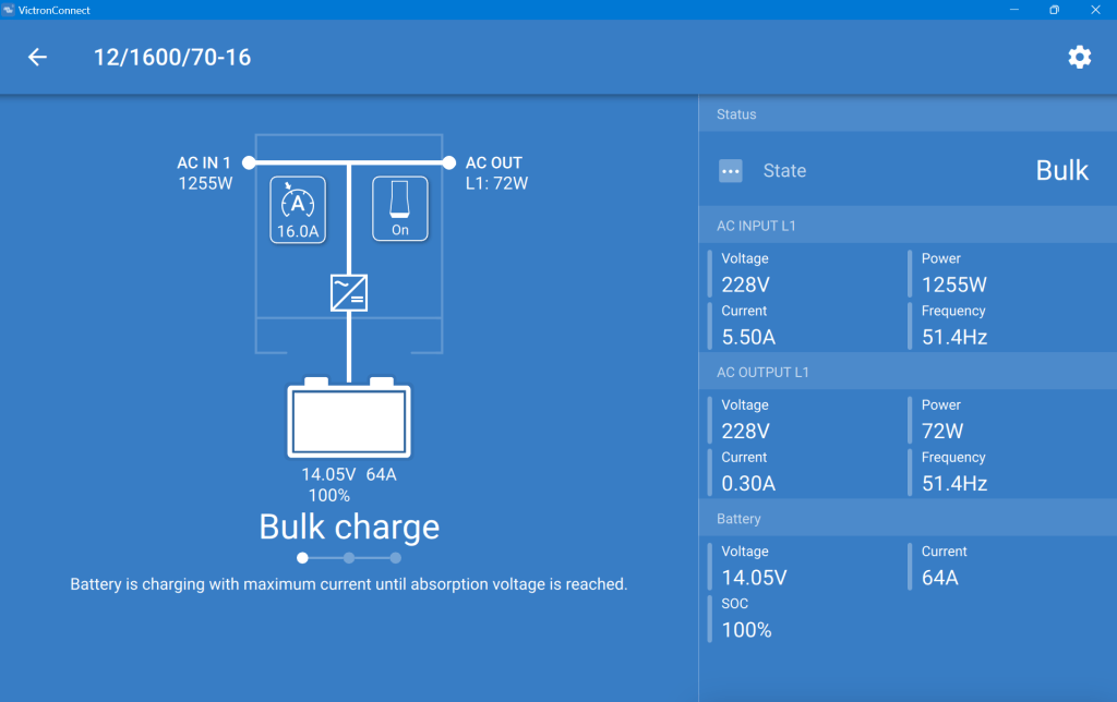
60%of the batteries (from 20% to 80%) within3h - We will be using Victron MultiPlus-II (as we do not 2 separate AC inputs)
Here is a list of devices needing electricity:
- Refrigerator (able to run on 12V DC/24V DC or 230V AC)
- Microwave (
1'000W) - Water heater (immersion heater with
1'000Wor2'000Wand/or kettle with2'000W) - Table grill (
1'250W) - Steam cooker (
450W/900W) - Bread baking machine (
600W) - Coffee machine (
1'150W) - Washing machine (
750W) - Water pressuriation system (
850W) - Computers peripherals (USB-C charging with 36W via AC or DC, or 60W AC)
- Lights (12V or 24V DC)
- Water pump (12V or 24V DC)
- Fan (12V or 24V DC)
- Diesel heater (12V DC)
- Starlink (
60WAC, possibly 48V DC) - Infrared heating panel (
150WAC) - Battery charger (12V/24V DC or 230V AC, depending on model)
- Other USB powered and/or chargeable devices (via 12V/24V DC or separate 230V AC charger)
- built-in 6t winch (powered by engine)
- (optional) electric shower (
8'000W)
Sizing the electrical installation comes with a number of additional constraints:
- The crane in the workshop garage can lift up to
500kg
this mean, all batteries, inverters, washine machine and water tanks must be less that weight - No single battery can charge or discharge with more than
140A - We can only charge from EVSEs with a Type 2 connector
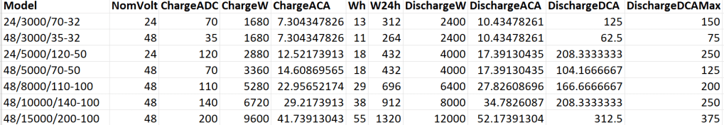
A 12V system is very quickly out of the picture (and the largest and only MultiPlus-II with 12V is a 3’000VA system). Besides, the truck has 24V system anyway. So it is either 24V or 48V. Here is an overview of all current 24V and 48V MultiPlus-II models and their charge and discharge values:
Let’s first evaluate a 24V system:
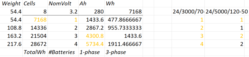
- 1* 8s battery
- Capacity is likely to be too small
- Single battery is not redundant
- 1*3’000VA can draw too much discharge current
- 1* 5’000VA can draw too much discharge current
- 2* 8s battery
- 2* 3’000VA can draw too much discharge current
- 1* 5’000VA possible
- 3* 8s battery
- 1-phase charge requirement can only be met with EVSE 7kW 32A Type 2
- 3* 3’000VA can draw too much discharge current
- 2* 5’000VA can draw too much discharge current
- 4* 8s battery
- 1-phase charge requirement can only be met with EVSE 7kW 32A Type 2
- 4* 3’000VA can draw too much discharge current
So, in a 24V 1-phase system only the 5'000VA inverter would be possible with either 2 (14’336Wh) or 4 (28’673Wh) batteries.
For a 3-phase setup to support our Kemppi Kempact 253A we would need at least 4 batteries and 3* 5'000VA inverters.
And now let’s have a look at a 48V system where we have a couple of more inverter options:

- 1* 16s battery
- Single battery is not redundant
- 2* 3’000VA inverters needed
- 1* 5’000VA inverter possible
- 1* 8’000VA can draw too much discharge current
- 1* 10’000VA can draw too much discharge current
- 1* 15’000VA can draw too much discharge current
- 2* 16s battery
- 1-phase charge requirement can only be met with EVSE 7kW 32A Type 2
- 3’000VA not as 3-phase setup feasible (otherwise 6 devices necessary)
- 8’000VA only as 3-phase setup, but then too heavy
- 1* 10’000VA possible
- 1* 15’000VA can draw too much discharge current
- 3* 16s battery
- 1-phase charge requirement cannot be met
- charge requirement can only be met with 3-phase EVSE (16A or 32A) Type 2 (11kW+)
- 3’000VA possible, but too heavy with combined battery weight
- 5’000VA possible
- 8’000VA only as 3-phase setup, but then too heavy
- 10’000VA only as 3-phase setup, but then too heavy
- 15’000VA possible
- 4* 16s battery
- batteries too heavy
- 1-phase charge requirement cannot be met
- charge requirement can only be met with 3-phase EVSE (16A or 32A) Type 2 (11kW+)
- 3’000VA too heavy with combined battery weight
- 5’000VA too heavy with combined battery weight
- 8’000VA only as 3-phase setup, but then too heavy
- 10’000VA only as 3-phase setup, but then too heavy
- 15’000VA only as 3-phase setup, but then too heavy
So, this leaves us with really 3+2 choices:
- 2* 8s (14’336Wh) batteries in a 1-phase system with a single 5’000VA inverter
- Battery and inverters would weigh roughly
140kg
- Battery and inverters would weigh roughly
- 2* 8s (14’336Wh) batteries in a 3-phase system with three 5’000VA inverters
- Battery and inverters would weigh roughly
250kg - Not possible for 3-phase welding
- Battery and inverters would weigh roughly
- 4* 8s (28’672Wh) batteries in a 3-phase system with three 5’000VA inverters
- Battery and inverters would weigh roughly
310kg
- Battery and inverters would weigh roughly
- 1* 16s (14’336Wh) battery in a 1-phase system with a single 5’000VA inverter
- Battery and inverter would weigh roughly
140kg
- Battery and inverter would weigh roughly
- 2* 16s (28’672Wh) batteries in a 3-phase system with three 5’000VA inverters
- Battery and inverters would weigh roughly
310kg - 3h on a 1-phase 16A Type 2 would charge about 38% (a 60% charge takes 4.7h)
- Battery and inverters would weigh roughly
From there, we can narrow this down even further:
1-phasesystem:24V, 2*8s- Price: batteries 2* 1’364GBP = 2’728CHF plus inverter 1* 1’359GBP total =
4'087GBP- Con: 24V MultiPlus-II are considerably more expensive (than 48V)
- Con: only have the capacity
- Con: cannot run electric shower
- Price: batteries 2* 1’364GBP = 2’728CHF plus inverter 1* 1’359GBP total =
3-phasesystem:48V, 2* 16s- Price: batteries 4* 1’364GBP = 5’456CHF plus inverter 3* 812GBP = 2’436GBP total =
8'802GBP- Con: charge requirement can only be met with 32A Type2 on 1-phase
- Con: additional 48V|24V DC-DC converter required
- Con: heavier, 300kg+
Con: higher self-consumption in 3-phase configuration
- Price: batteries 4* 1’364GBP = 5’456CHF plus inverter 3* 812GBP = 2’436GBP total =
So – drum roll – my conclusion: for roughly double the money in a 48V we would get double the capacity and triple the charge and output power and pretty much can do everything we want the system to be able to do.
The 3-phase system can be reconfigured to a parallel 1-phase system, so we would even be able to use an electric shower (though very unlikely – we have our mobile shower). We can either charge 1-phase or 3-phase and have a longer window of electric autarky. And for most of the time we would leave the system in a 1-phase single device InverterCharger configuration. And additionally, for charging the other 2 devices would bet set to ChargeOnly (but be configured independently configured from each other).
The exact setup I will have to layout some other time, but right out of my head I would think of the following components:
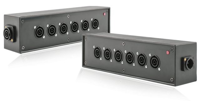
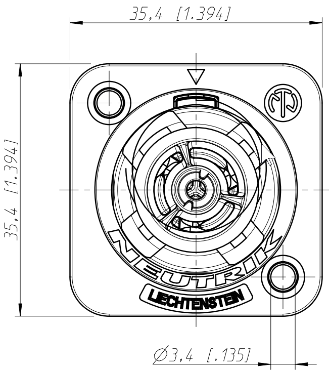
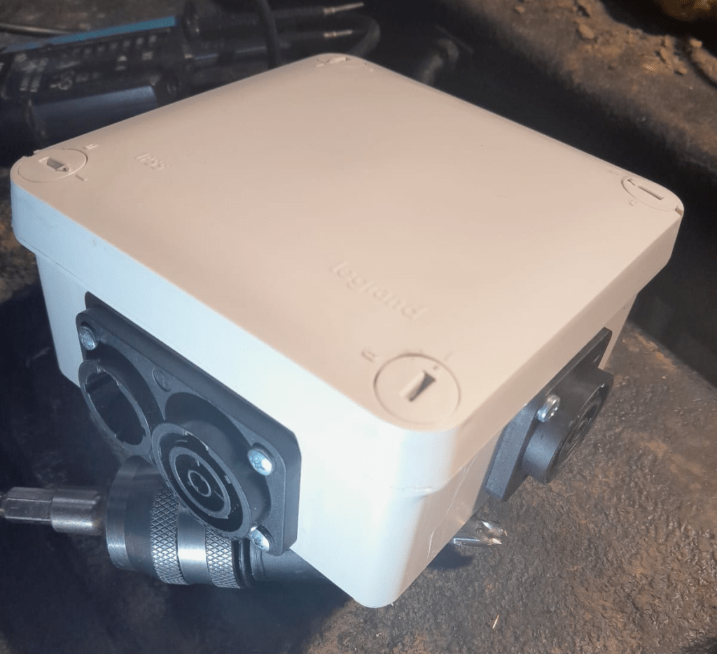
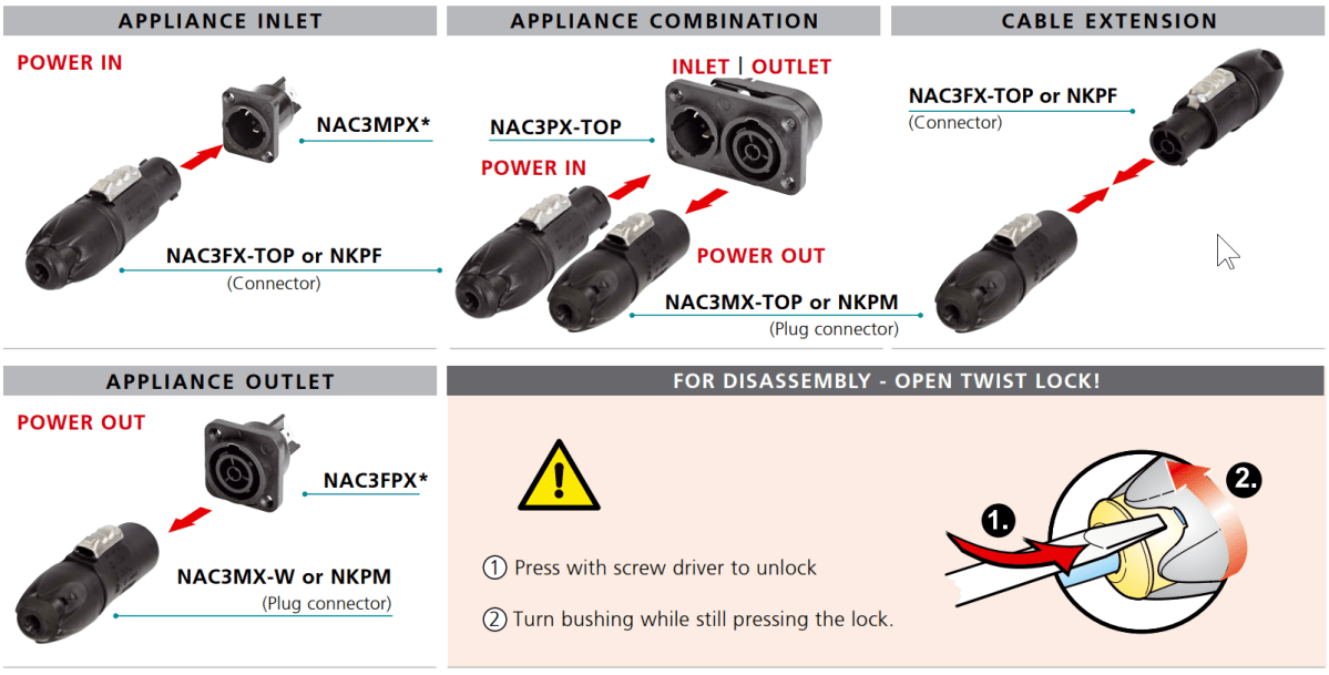
- External power in with CEE 16-5, CEE32-5, CEE32-1, CEE16-1 and Neutrik PowerCON True1 TOP (the more the better)
connected to an ATS - AC out from MultiPlus-II connected to ATS
- Orion-Tr 24V|48V DC-DC converter
charging from alternator (though not the norm) - Orion-Tr 48V|24V DC-DC converter
as power supply: to support 24V loads in the container
as charger: as an emergency charger for the truck batteries - Lynx Power In, Distributor
- Venus OS with Raspberry PI for RS-486 and DVCC
So, in case our Saurer ever gets finished – at least I know how to do the electricity …