WMF Lono Quadro mobile BBQ and the Victron MultiPlus Compact 24/1600/40-16

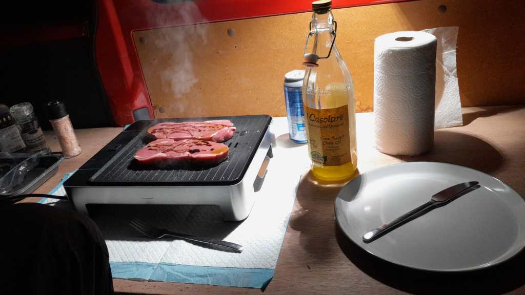
Though this could have been our first “unboxing blog post” in this article we only describe an already unboxed table grill.

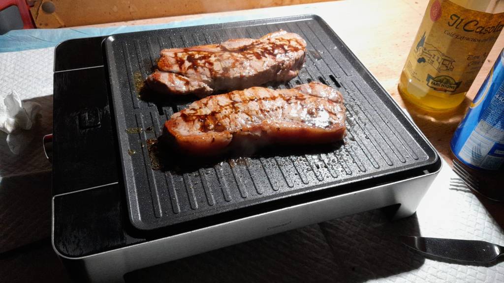
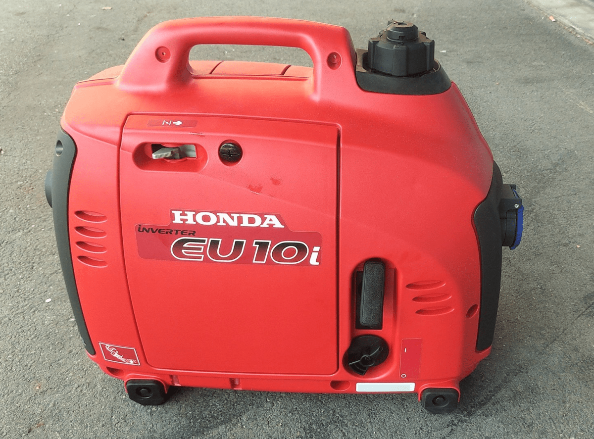
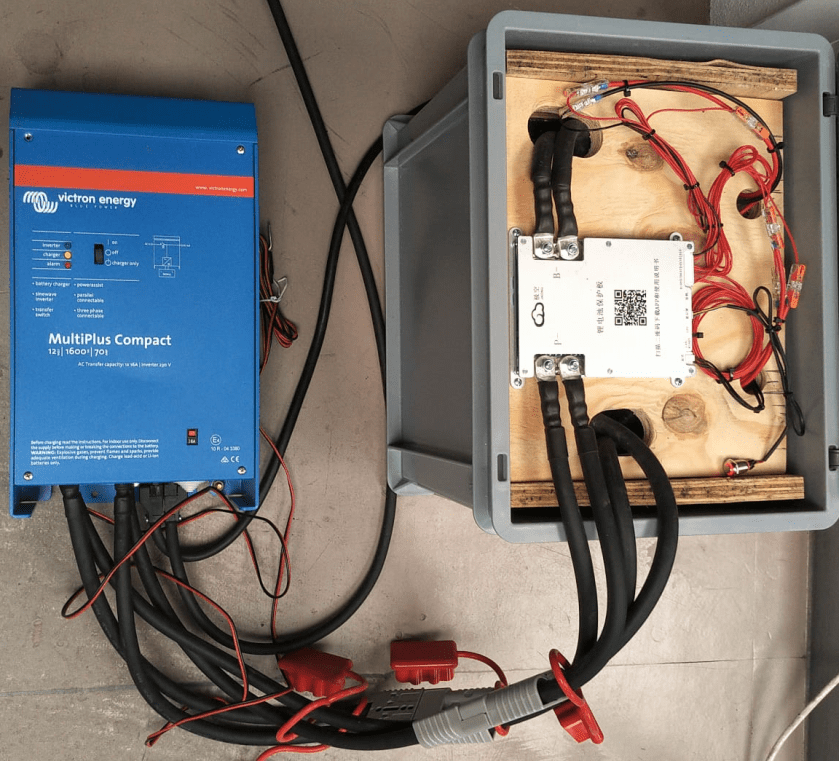
Being able to have fires in the open less and less often it was time to find an electric BBQ alternative – with the constraint that it should run on a Victron MultiPlus Compact 24/1600/40-16 (or any other 1600VA sized inverter). After some frustration we finally found a nearly perfect match: the WMF Lono Quadro.

According to its spec sheet and product brochure, it uses 1250W – which is just under the nominal maximum power of 1280W that the MultiPlus can deliver.

Plus, the BBQ is relatively cheap. With a MRSP of 79.99 EUR it is available for as low as 60 EUR (PP included depending on your location). So, we ordered one of these table grills and gave it a try.

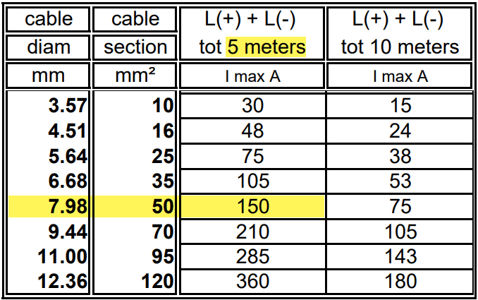
Upon powering up the device it uses its full power (regardless of the dial setting 1 .. 5) which results in a current draw of around 50A as seen on the BMS. The setting of the dial only seems to affect the intervals between heating (drawing current at 50A) and not heating (not drawing current at all).

The initial heating phase lasts naturally longer which results in the fan of the inverter kicking in at some point. But once the BBQ is at its operating temperature the fan is silent most of the time (as the heating intervals are relatively short). With 1250W nominal power consumption and a heat-up time of around 5min this consumes roughly 104Wh – about the same energy to boild 1.1l of water from 20°C.

During the use of the BBQ the inverter is pretty much at its power maximum and so has little to no resources left to power anything else. Though it seems possible to leave a fridge running, it might be better to unplug any consumers during cooking.

But all in all, with this table grill we now can do the BBQ inside (or outside) in our Toyota HiAce – even when we are on the move.

Some additional observations:

  • Weight
    The device is relatively heavy – especially the grill plate.
  • Size
    The usable size of the BBQ (270mm x 270mm) in relation to its overall dimensions seems quite large (while the whole device is still not bulky).
  • Power consumption
    Though the power consumption is rated at 1250W the heating intervals are relatively short which turn leads to a moderate overall power consumption.
  • Cleaning
    The grill plate can easily be removed and thus easily be removed (even in a dishwasher if you happen to have one in your car). Also, the drip tray can easily be removed and cleaned. Only the base plate is not meant for dishwashing.
  • Drip tray
    If the BBQ is not positioned horizontally (maybe due to the parking position of the vehicle) then the drip tray might have difficulties to catch all the fat that might float around the grill plate.

And this is it for today. Happy BBQing …

WMF Lono Quadro running from a Victron MultiPlus Compact 24/1600/40-16 at roughly 1250W/50A
Heat-up time is roughly 5min when turning the dial to the maximum position

Honda EU 10i: a perfect backup for the Victron MultiPlus-II 24/3000/70-32

In our trailers and vehicles I prefer 24V 8s batteries, as the price-weight-power triangle of our Eve 280Ah cells is hard to match. With a gross weight of roughly 55kg we get a nominal “capacity” of 7168Wh. Even at a low cell voltage of 2.7V we can still get more than 2400W (3000VA) out of the battery. Exactly what a Victron MultiPlus-II 24/3000/70-32 (or any 3000VA inverter/charger for that matter) can deliver.

The Honda EU 10i has a sustained output of 900W which equates to roughly 3.9A at 230V. Now, this is not too interesting by itself.

However, the minimum AC current input of the MultiPlus is 3.6A. So, exactly within the range of the Honda EU 10i. A 5000VA inverter for example, would drain the generator with its minimum input of 4.6A+. And with its fuel tank capacity of 2.1l it runs nearly 4h on full load. Which in turn means, I can charge our 24V 8s battery about 50% without refueling.

Note: ideally we would charge it from 25% up to 75% SoC.

So, for me this generator is the ideal backup when I am away without any EV station nearby. With its 13kg and small form factor (and price) there is always a place in my vehicles where I can put it.

And as a side benefit: when I run the generator along with the inverter I can generate up to 3300W (or over 14A). That is: run my oven and boil potatoes at the same time …

And the generator even makes sense when combined with a Victron MultiPlus Compact 24/1600/40-16 (or its 12V counterpart). They are the smallest inverters/chargers in that power range. They strong enough to run a coffee machine or immersion water heater, but are not pwoerful enough to run a full 2000W appliance. However, in combination with the Honda, they just reach 2180W. Of course, charging a 24V 8s battery with a “Compact” device takes much longer, due to its smaller charger.

Twitter – Honda EU 10i in action

Changing the cabling of a Victron MultiPlus Compact 12/1600/70-16 from 35mm2 to 2* 35mm2

In this article I describe what I did to install 2 pairs of 35mm2 cable to a Victron MultiPlus Compact 12/1600/70-16.

Out of the box the MultiPlus comes preconfigured with a pair of 1m 35mm2 (2AWG) welding cables (and as a side note: with unusually thin M8 cable lugs).

When connected to a 12V battery based on 4s Eve LF280K cells, the maximum current drawn can go beyond the recommended 0.5C rating – especially when the cell voltage decrease under the nominal 3.2V or the total cable length is longer than 1m. Using a larger inverter or smaller cells will make things even worse.

And when we look at Victron’s Recommended battery cables document, we see that they are recommending 50mm2 for currents up to 150A anyway (for cable lengths of up to 5m).

Victron recommended battery cable sizes, copyright https://www.victronenergy.com/upload/documents/BatteryCables.pdf

For a 1m cable the theoretical voltage drop is within their recommended range of 0.259V. But they explicity state that resistance leading to additional voltage drop due to contacts is not calculated into the recommended cables size.

Already a cable size of 2m will lead to over 3% and 0.3V voltage drop when the cell voltage is only 4* 2.6V = 10.4V (and by default raise a “Low Voltage Alarm” on the MultiPlus). And even a cell voltage of 4* 2.75V = 11V is close to 3% and over the recommended threshold (of course, calculation is based on full inverter load of 1600VA). Besides Victron explicitly recommends a voltage drop of under 2.5% in their Wiring Unlimited document.

So why is Victron fitting the inverters with only 35mm2 cables? Especially since they are using welding cables that are only rated up to 60°C. I do not know.

But I do know, how I can fit an additional 35mm2 pair into the inverter and minimise a potential heating problem.

Adding a second pair makes particular sense at least in my case, as I am using a JK-BMS and Eve cells that both come with two M6 terminals per connection point. So running two cable pairs to battery and BMS saves me from using a bulkier and stiffer 70mm2 cable that I would have to split at the BMS and main positive cell anyway. And with that, I can still use the Anderson SB175 connectors with regular housing and 1383 wire contacts and without having to resort to 2/0 housings and 1328G1 wire contacts.

The inverter comes with 30mm holes in the front panel where the supplied cable is fitted with an M25x15mm cable gland (side note: why are they using IP68 glands when the whole inverter is only rated at IP21). Eland H07RN-F 35mm2 cable has a diameter of 14.6mm, so actually two of these cables do not fit through the holes at once.

But as the cable lugs are actually that long that they stick out of the chassis the required diameter is 2* 12.5mm = 25mm which is just the size of the hole. When wrapped in heat shrink we need some more space. And certainly we want a little bit of head room, so the cables do not scratch against the metal when moving.

Klauke 105R8 M8 35mm2 dimensions, https://www.klauke.com/kr/en/compression-cables-lugs-to-din-cu-4935

So, the M25 holes had to be enlarged slightly to make space for the double cable lugs as seen on the picture below. I used a Hilti GDG 6-A22 grinder for this. I covered the inverter to prevent metal splices and dust getting inside (board, circuity) of it. And I added extra insulation around the cable lugs to prevent them cutting into the metal.

Bottom side of MultiPlus with enlarged holes and extra cable insulation

Mounting the cables to the connection points is done with two Klauke M8 35mm2 DIN 46235 compression cable lugs (back to back).

Note: the compression cable lugs from Weidmüller will not fit, as their connection plate is too long.

Instead of the factory supplied washers, spring locks and nuts, I use M8 serrated washers and lock nuts. As the negative connection point (which is directly under the 250A MEGA fuse) is around 2mm higher than with only one cable lug, I added an additional (copper) washer under the fuse terminal to make more space.

I could cover the original bolts with insulation tape to prevent accidental contact with the chassis when squeezed (but this is something that could have happened even before).

Victron MultiPlus Compact 12/1600/70-16 with dual 35mm2 battery cables

Now we have a 2* 35mm2 = 70mm2 connection to our battery as seen below.

2* 35mm2 connection between battery and inverter

So the voltage drop over the whole cable (1.5m from invert to battery with 70mm2) should be around 114mV:

Voltage drop at different cell voltages

So as it seems, the main difference between the larger and the smaller cable is the power loss (17.22W vs 34.44W at full power or 15W vs 30W at 0.5C). So all in all we save nearly 0.84% battery capacity per cycle with the thicker cables (which is 5000Wh over the whole cell life) – probably less than we spend on the cables and lugs, the labour and the time to do the calculation and writing up the article …

Building a battery case for a 4s Eve LF280K configuration

Based on our Eve 8s design, I made a sketch for a 4s 12.8V battery, which I could later connect to a Victron MultiPlus Compact 12/1600/70-16:

Wooden case for the 4s Eve LF280K battery

Again, this battery has a wooden inner case and sits inside a utz 400mm x 300mm x 325mm RAKO container.

There are a few differences however:

  1. There is no space for fuses inside the container
    (so it is more like a traditional battery);
  2. all bus bars are “bent” and not straight
    (we need three 35mm2 pairs, so six cables altogether);
  3. main positive and main negative are on the opposite sides of the cells;
  4. I use a JK-BMS B2A8s20P without soldered cables but with dual M6 threads
    (so I can use 35mm2 cables all the way).
utz RAKO 400mm x 300mm x 325mm container with wooden frame

To cut the plywood in an efficient way, I used a web site called cutlistoptimizer which gave me this result:

Cutting suggestion by https://cutlistoptimizer.com/

For this build, I planed all the boards after cutting, before putting in the cells. With this, I hoped to minimise the chance of any particles on the board damaging the cell insulation.

And for the small board at the short side of the case, I did also use 20mm plywood, but planed it several times until it I could just slide it in.

This is how the wooden case looks with the cells and insulation boards (shown in red):

Top view: battery cells with depicted insulation boards (shown in red)

Note: when using a JK-BMS I found it important to have the main negative connection point on the upper left (or lower right). Only with this orientation it was (relatively) easy to connect the cell to the BMS.

BMS connected to cells

It needed some fiddling to get the main negative cable pair to the BMS and the main positive cable pair out of the frame, as we can see from the image above.

The connection to the individual cells are fed through WAGO 221-2411 2 conductor inline splicing connectors. The holes into the top board were done with a forstner bit and a jigsaw. This version of the BMS can be fixed with four screws to the board (so no need for wire straps as with the 24s version).

Again, instead of a display I just used the pluggable power button that is connected to the display port of the BMS to power on and off the device.

In the end, I added Anderson SB175 connectors and 1383 (2AWG) contacts to both pairs and connected them to the inverter.

Battery connected to inverter

Some more details

  • All 35mm2 cables are Eland H07RN-F flexible rubber cable;
  • compression cable lugs are Klauke M6 35mm2 DIN46235;
  • cell contacts were secured with M6 serrated washers and M6 16mm steel bolts;
  • BMS threads B- and P- were secured with M6 lock nuts to M6 16mm steel bolts (with the bolt upside down);
  • cell wires from the BMS were fitted with uninsulated ferrules;
  • cell wires on the positive cell poles were fitted with ring lugs and a 2.5mm2 hookup wire;
  • I added handles to the SB175 connectors to facilitate disconnecting the cable pairs;
  • I added dust covers to the SB175 connectors;
  • all compression cable lugs and the SB175 were crimped with a Hilti NUN54-22;
  • all cable lug connections and Sb175 were heat shrinked;
  • I added 2*35mm2 cable pairs with SB175 connectors to the inverter by replacing the existing 35mm2 welding cable with M8 lugs (you still need M8 lugs on the inverter positive and negative terminals).

Things to improve next time

  • Mount the SB175 connectors to the outside of the container
    With this the lid can be closed and the cables and BMS are better protected against pulling;
  • add 3A inline fuses to the cell wires;
  • use 45° angled cable lugs for main positive and main negative to make it easier to get the wires routed outside the container;
  • feed an additional wire pair for the voltage sensor from the main positive outside the container to be able to connect it to the inverter (but I am not too sure about this, as I think the voltage drop on the 2*35mm2 connection is neglectable – it might better to add a temperatur sensor to the main positive):
  • maybe add protective wire sleeves to the SB175 connectors (but they are quite expensive):
  • add a Victron MK-3 USB-C interface with RJ-45 cable into the case (to be able to restrict AC power on the inverter).

What did it cost?

Cost calculation for the 4s battery including case and inverter

Summary

This case is not as complete as the 8s version – due to its form factor. Neither the inverter has an RCBO nor the battery has a DC MCB. This has to be added separately (incurring additional cost and space). As written above, the 4s version is more like a traditional battery. However, the form factor is quite compelling; 3.5kWh in 400mm x 300mm x 325mm case. Especially in combination with the compact edition of the Victron MultiPlus. And the cost (as always without labour) is very reasonable, as well.

The inverter delivers 1200W constant power – in my opinion, enough for a small and mobile electricity build. Runnig a Krups Inissia Nespresso machine is not a problem, and boiling water with our 1000W immersion heater neither. Worst case, you could also run a 300W infrared panel heater for more than 11 hours.

One drawback of the inverter is probably the relatively small charger. With 70A at 12V it can only charge the battery with around 840W. This is certainly not the problem of the battery which would support charging up to 1344W.

Recovering a Victron MultiPlus Compact 12/1600/70-16 after a failed firmware update

The other day, I received my Victron MultiPlus Compact 12/1600/70-16. One of the first steps to do upon commissioning was to update the firmware. In my case from v481 to v502.

With my Windows PC running the latest VictronConnect App and a MK3 to USB-C Interface, I connected to the MultiPlus and enabled the advanced settings by entering the infamous zzz password (which you officially can only get from an official Victron training or distributor or simply by searching the internet).

I was offered to install 2606502.vff to which I happily clicked OK. So it seemed, I was running on a new microcontroller with 230V (hence 26) and really had a MultiPlus Compact 12/1600 (06). But I did not know this at that time.

Note: For a list of the current model numbers see the document VE.Bus firmware versions explained and its link to VE.Bus firmware versions explained on Professional Victron Energy (account needed).

After a couple of seconds into the update process, the operation stopped by telling me something failed. And after a restart, the only thing I could see was the yellow LED constantly flashing as soon as power was connected to the device and regardless of the main switch position.

Victron MultiPlus Compact flashes yellow after failed firmware update

When I tried to reconnect with the VictronConnect app, the detection phase took very long – but the MultiPlus was not recognised.

VictronConnect trying to detect the MultiPlus after the failed firmware update
Detection unsuccessful after the failed firmware update

Even when I tried the “Force detection” option (which is intended to be used after a failed firmware update) no usable result was yielded.

“Force detection” did not work either

So, then I resorted to VEFlash (which is deprecated and has to be selected explicitly when installing the Victron tools on Windows).

But this did not work either, as it could not find anything behind the MK3:

VEFlash failed to recognise the MultiPlus

However, having a closer look at the hints VEFlash gave me before the recovery I was confused that VEFlash asked me to unplug the AC power source. How would I be able to update the firmware? Via DC? And why would it matter anyway which power source was connected?

VEFlash hint at not using AC power on a MultiPlus Compact

So I carefully re-read the VE.Bus Configuration guide and apparently the connection would have to be made via DC as it is pointed out in Chapter 5 Connecting:

MultiPlus Compact requires DC power source

How strange. And even stranger – it worked!

Using a Blue Smart Charger as a DC power source for the MultiPlus

As soon as I connected a Blue Smart IP65 Charger in “Power Supply” mode to it (and configured a voltage of 14.4V) the “Force detection” option in VictronConnect worked.

Note1: I did not alter any of the DIP switches as recommended by VEFlash.

Note2: when reading the manual I learned about the firmware numbers and where to download them. The current firmware is on https://updates.victronenergy.com/feeds/VEBus/firmware-archive/ and not on https://professional.victronenergy.com.

I was then again presented with the option of a firmware update which eventually succeeded.

And the MultiPlus is running happily on 2606502 ever since …