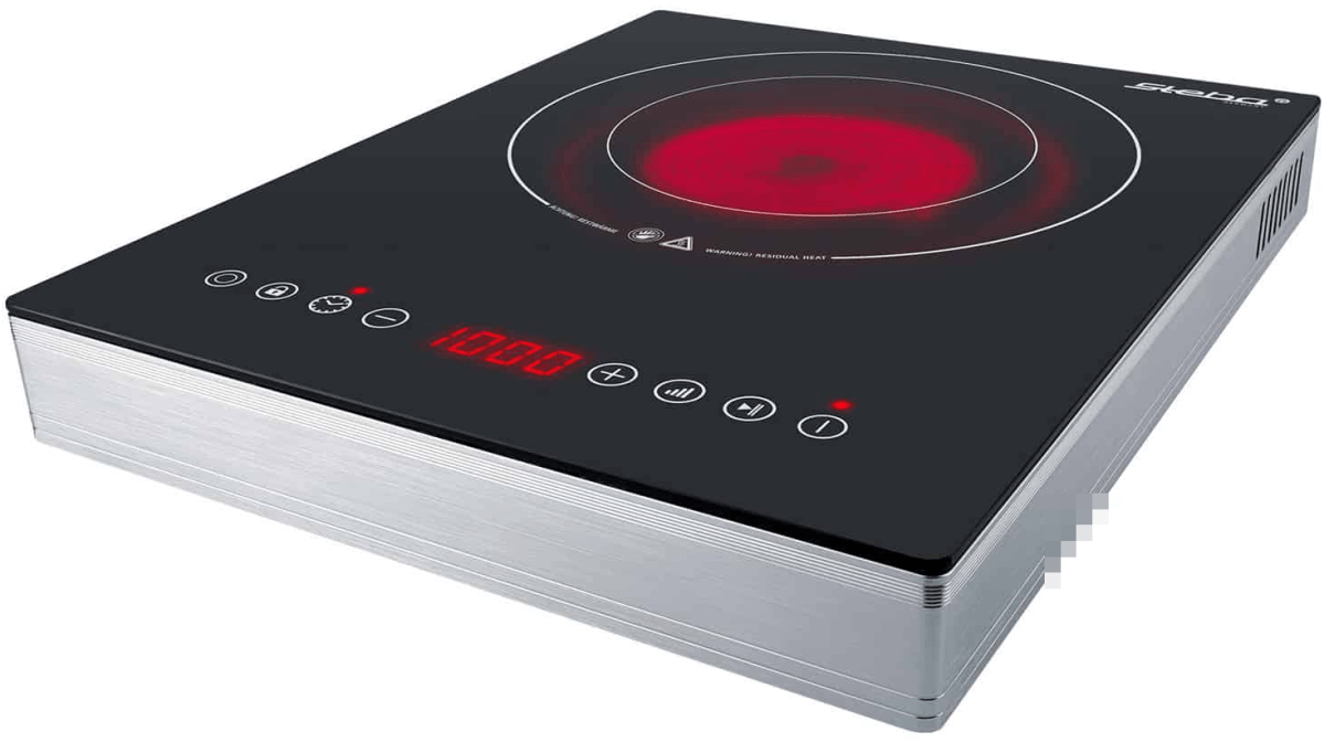
In order to cook in our Toyota Hilux and Toyota Hiace we use a glass ceramic hob Steba HK 30 that – according to the manufacturer – allows for precise adjustment of the power consumption from a company called Steba. However, in reality these ratings seem to be different. In this article, I give an overview of the energy ratings I measured.
Observed Power Consumption
The hob has 2 rings with a nominal rating of
Ring 1 100w, 400W, 600W, 700W, 800W, 900W, 1’000W
Ring 2 200W, 800W, 1’200W, 1’400W, 1’600W, 1’800W, 2’000W
In the table below you see the actual values I measured in comparison to the nominal values as shown on the hob. For our Victron MultiPlus Compact 24/1600/40-16 the highest setting is on Ring 2 with 1600W nominal.
Ring
Wnominal
Waverage
Wmin
Wmax
0
0
0
0.4
4.1
1
100
200
225
254
2
200
450
417
459
1
400
400
375
409
1
600
475
450
477
1
700
600
580
602
1
800
700
708
731
2
800
750
699
770
1
900
860
850
863
1
1’000
930
932
934
2
1’200
900
863
901
2
1’400
1’150
1’108
1’148
2
1’600
1’400
1’368
1’396
2
1’800
1’650
1’645
1’659
2
2’000
1’800
1’787
1’795
Energy ratings of Steba HK 30
Other Observations
There are a couple of (negative) things that I noticed when using this hob:
When using the outer Ring 2 (or the full hob) the lowest level you can choose is 200W or then already 800W which turns out to be too much when trying to cook for a longer period of time. In my case, I use a large cast iron pot and let it cook for 4h to 5h. With 200W it was too little and with 800W it effectively started burning its contents at the bottom.
After 2h – 3h of constant use the hob once switched off after the pot boild over and spilled sauce on the hob. But I do not know if this was just a coincidence. After turning it back on it worked without interruption for another 2h – 3h.
The hob pulses when heating, i.e. turning the heating rings on an off very quickly. This seemed to stress the inverter when it was connected to mains (which was another inverter on batteries). For whatever reason it quite often drew power from the battery instead from mains.
After use the hob keeps a ventilator running for approximately 15min. It is rather on the loud side but not necessarily disturbing. Power draw during the cool down phase is 4W. When cooking something on the move one has to take that duration into consideration before switching it off.
The device is relatively bulky for that it is meant for only a single pot.
Summary
Most of the devices are not perfect (as described in the observations above). But all in all I really like the hob and we use it quite often. It is easy to clean and usable over several hours of constant use. Bon appetit.
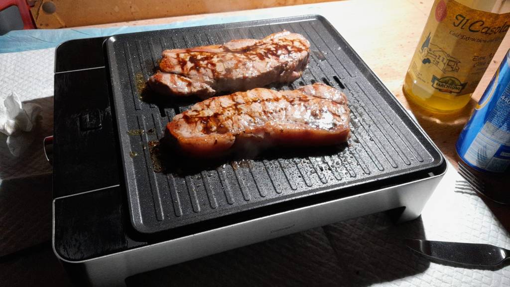
Pulled Pork cooked on the Steba HK 30 with a Victron MultiPlus ( 1 )Pulled Pork cooked on the Steba HK 30 with a Victron MultiPlus ( 2 )Steba HK 30, taken from https://steba.com/produkte/glaskeramik-kochfeld-hk-30
Though this could have been our first “unboxing blog post” in this article we only describe an already unboxed table grill.
Being able to have fires in the open less and less often it was time to find an electric BBQ alternative – with the constraint that it should run on a Victron MultiPlus Compact 24/1600/40-16 (or any other 1600VA sized inverter). After some frustration we finally found a nearly perfect match: the WMF Lono Quadro.
According to its spec sheet and product brochure, it uses 1250W – which is just under the nominal maximum power of 1280W that the MultiPlus can deliver.
Plus, the BBQ is relatively cheap. With a MRSP of 79.99 EUR it is available for as low as 60 EUR (PP included depending on your location). So, we ordered one of these table grills and gave it a try.
Upon powering up the device it uses its full power (regardless of the dial setting 1 .. 5) which results in a current draw of around 50A as seen on the BMS. The setting of the dial only seems to affect the intervals between heating (drawing current at 50A) and not heating (not drawing current at all).
The initial heating phase lasts naturally longer which results in the fan of the inverter kicking in at some point. But once the BBQ is at its operating temperature the fan is silent most of the time (as the heating intervals are relatively short). With 1250W nominal power consumption and a heat-up time of around 5min this consumes roughly 104Wh – about the same energy to boild 1.1l of water from 20°C.
During the use of the BBQ the inverter is pretty much at its power maximum and so has little to no resources left to power anything else. Though it seems possible to leave a fridge running, it might be better to unplug any consumers during cooking.
But all in all, with this table grill we now can do the BBQ inside (or outside) in our Toyota HiAce – even when we are on the move.
Some additional observations:
Weight The device is relatively heavy – especially the grill plate.
Size The usable size of the BBQ (270mm x 270mm) in relation to its overall dimensions seems quite large (while the whole device is still not bulky).
Power consumption Though the power consumption is rated at 1250W the heating intervals are relatively short which turn leads to a moderate overall power consumption.
Cleaning The grill plate can easily be removed and thus easily be removed (even in a dishwasher if you happen to have one in your car). Also, the drip tray can easily be removed and cleaned. Only the base plate is not meant for dishwashing.
Drip tray If the BBQ is not positioned horizontally (maybe due to the parking position of the vehicle) then the drip tray might have difficulties to catch all the fat that might float around the grill plate.
And this is it for today. Happy BBQing …
WMF Lono Quadro running from a Victron MultiPlus Compact 24/1600/40-16 at roughly 1250W/50AHeat-up time is roughly 5min when turning the dial to the maximum position
However, in this case we wanted a kind of “special” setup which included the use of MultiPlus Assistants. So, in this article I will quickly describe what we wanted to achieve and how we implemented it.
In general, when connected to shore power we want to be able to limit the AC current drawn from the shore power. This is easily accomplished by setting a limit on the MultiPlus itself – or, as in our case, via the VE.BusSmart Dongle. Though the Phoenix does have a VE.Direct interface and is able to be connected to a GX device, in our setup we did not want to use a GX device. So, essentially the Phoenix can only be controlled via Bluetooth and the VictronConnect app. But configuring the AC input limit on two devices (Phoenix and MultiPlus) is not only a nuisance from a usability standpoint, but also error-prone as one (or at least we) tend to forget things quickly. So, a different and better solution was needed.
Enter the MultiPlus Assistant in form of the Programmable Relay. With this, we can configure the built-in relay of the MultiPlus to open and close based on the availability of an AC input.
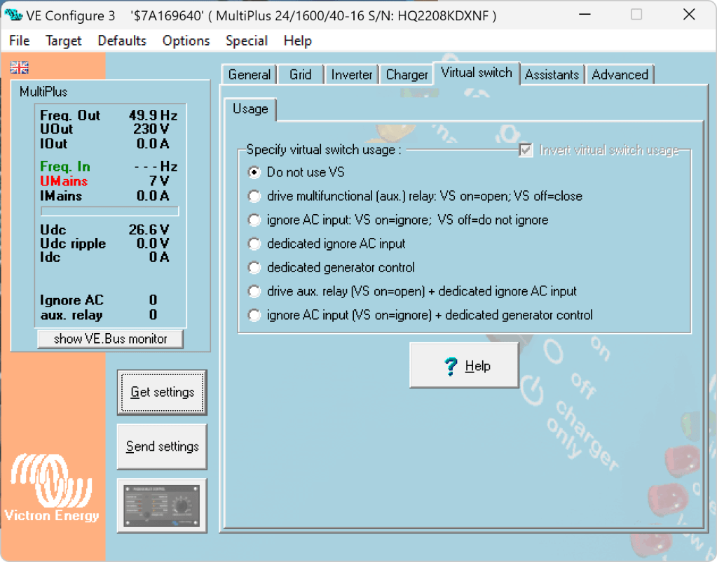
Note: we have to disable “Virtual Switch” in the MultiPlus to be able to use the MultiPlus Assistant.
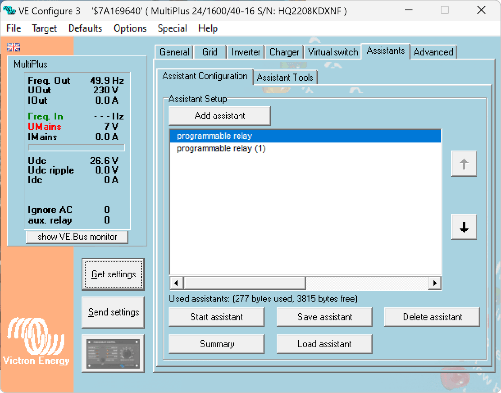
The Phoenix has a Remote Input connector, that can be used to stop charging when the connection is “off”. So in our case, we enabled two Programmable Relay assistants:
Programmable Relay, NC – On/Open After 5 seconds of AC input on the MultiPlus the relay is opened.
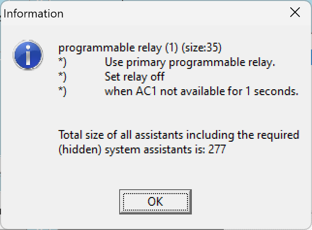
Programmable Relay, NC – Off/Closed After 1 second of no AC input on the MultiPlus the relay is closed (which is the default state).
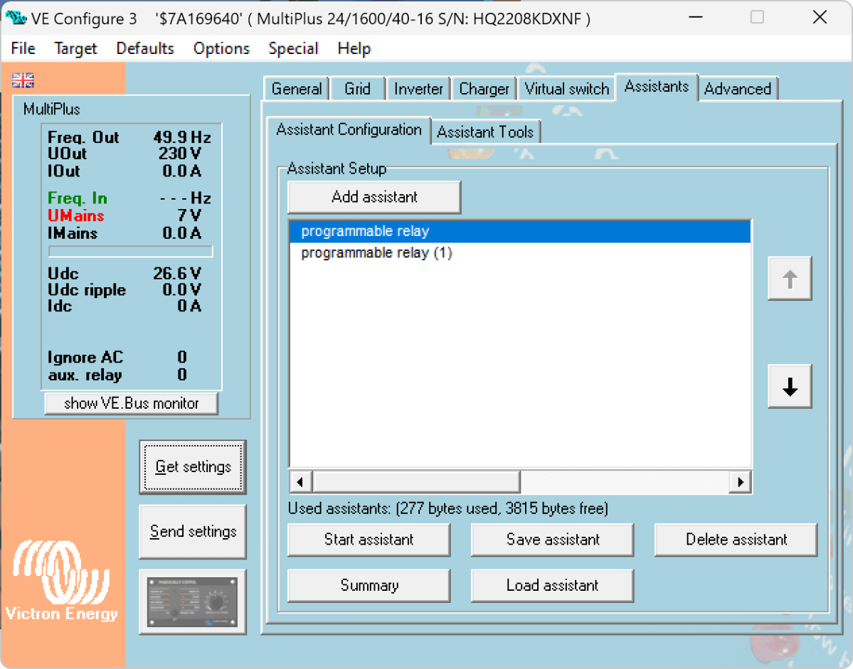
Below you find some screenshots with the configuration in VE Configure:
Disable Virtual Switch on MultiPlusAdd 2 Progammable Relay assistantsProgrammable Relay ON after 5 secondsProgrammable Relay OFF after 1 second
So, five seconds after the MultiPlus has power via AC input it will open the relay which in turn will enable the Phoenix to start charging.
One second after AC input is gone the MultiPlus will close the relay so the Phoenix will stop charing (if it was charging at all).
The AC input of the Phoenix is connected to the AC output of the MultiPlus. So, when there is a AC input limit configured on the MultiPlus (such as 3A @230V) the MultiPlus and the Phoenix will not be able to charge with more than 3A. And from the MultiPlus perspective, the Phoenix is just an arbitrary consumer.
This can lead to some undesired behaviour if we were to limit the AC input to e.g. 1A. In this case, the MultiPlus would – when in Inverter mode – draw from the battery so the Phoenix could charge the battery. perpetuum mobile … ? And when the AC input is gone, this means that for roughly one second the Phoenix will also charge form the battery. But this is something I can live with easily.
And if we really had a very low power AC input (of e.g. 1A) we can still unplug the remote input and force the Phoenix not to charge. Or manually switch the MultiPlus to Charger mode only.
For us this is a usable solution without the need for multiple configuration changes nor the presence of a GX device.
Now, that we got our Toyota HiAce we thought it might be a good idea to add more power to the vehicle: in form of an 8s EVE LF280K LiFePO4 battery and a Victron MultiPlus Compact 24/1600/40-16 inverter/charger. In the following, we describe our setup and the reason why we built it like this.
The Requirements
The sustained output power of the inverter must be over 1'200W.
Charging via AC via EVSE or generator must be possible.
Charging via alternator must be possible (but is not the norm).
Charging of 60% of the battery (from 20% – 80%) via AC should take less than 180min.
The installation should use the minimum amount of space possible.
We should be able to use our existing Eve LF280K cells, thus limiting the overall current to 140A.
As the vehicle will not have a diesel heater, it should be possible to run a 150W infrared heater for at least 3 * (4+2)h = 18h (^= 2'700Wh).
In addition, the battery should be able to run a refrigerator with an average power consumption of 50W for at least 72h ^= 3'600Wh (next to other power consumption).
Design Considerations
With a maximum current of 140A and a cable run length of 1.5m, we should plan with a cross section of at least 35mm2.
Basically, with Eve LF280K cells we have three choices regarding the battery size:
1* 4s (“12V”) Configuration 4 * 3.2V * 280Ah = 3'584Wh This would lead to a required nominal AC charge power of at least 716.8W/h and a charge current of at least 56A/h.
2* 4s (“12V”) Configuration 2* 4 * 3.2V * 280Ah = 7'168Wh This would lead to a required nominal AC charge power of at least 1'433.6W/h and a charge current of at least 112A/h.
1* 8s (“24V”) Configuration 8 * 3.2V * 280Ah = 7'168Wh This would lead to a required nominal AC charge power of at least 1'433.6W/h and a charge current of at least 56A/h.
The Victron MultiPlus Compact xx/1600VA inverter/charger provides enough sustained power output (while being smaller than the non-Compact edition). Depending on the voltage of the battery, this will slightly impact the amount of charge current.
To charge the battery via the alternator we would need a DC/DC converter that depends on the battery configuration as well (either 12-12 or 12-24). So, let’s have a look at the battery first.
1* 4s (“12V”) Configuration
The smallest, lightest and cheapest configuration. But capacity requirements regarding the fridge are only fulfilled, if there are no other loads. In addition, the discharge current is relatively high (scratching the maximum discharge rate of 0.5C).
2* 4s (“12V”) Configuration
More complex setup, as each battery needs a separate BMS, which leads to the need of an aggregator for both batteries to correctly report SoC and calculate CCL and DCL. In addition, more cabling and fusing is required (and probably to a large bus bar). Comes with the advantage of having a redundant battery in case a single battery fails. Most expensive configuration.
1* 8s (“24V”) Configuration
Custom battery build needed, as there is not enough space for a typical 2 * 4 cells setup behind he seats. But, only a single BMS and thus less wiring is needed. Comes with a slight disadvantage of not having native 12V from the battery. This is actually not an isse, as all our DC devices also accept 24V. Cells can better balance voltage differences across a single 8s bank.
The Setup
In the end, I decided for the 8s configuration, due to less complexity. Splitting the 8s configuration across two cell blocks seemed to be an acceptable compromise.
As a regular MultiPlus 24/1600/40-16 would not fulfill my AC charge requirements, I had to decide to either add a second MultiPlus or to add a dedicated charger. I opted for a Phoenix Smart IP43 Charger 24/25 instead of a second MultiPlus. The MultiPlus in parallel would always consume 10W though most of the time I would not need the output power. Whereas, the Phoenix would only need power, when connected to AC. And reconfiguring the MultiPlus every time I charge was not an option for me. And yes, I lose redundancy – but also save some money (Phoenix is much cheaper). So, in the end the nominal charge power is 40A + 25A = 65A, which lets me charge at 1'560W reaching 60% within 165min.
The HiAce comes with a 70A alternator, so I chose a Orion-Tr Smart 12/24-15 DC-DC Charger. With this charger, I could run the engine in standby and still have the car heater running. And this is probably the predominant use case (if charging via alternator at all).
For the DC bus bar I went for a Victron Lynx Distributor, so I could use and install MEGA fuses. Having a 1’000A bus bar seems certainly overkill, but a separate bus bar and fuse box that accepts 35mm2 cable and MEGA fuses would be not be much smaller.
I changed the existing AC inlet of the HiAce to Neutrik PowerCON True1 TOP (congrats to the marketing department, I am still amazed how this name rolls of the tongue) and installed 2 Siemens compact 16A CRCBOs (external AC in, internal AC out). I am aware that theoretically I could support more than 16A on the internal AC out (via PowerAssist). If ever needed, I can replace the RCBO with a 20A version.
I added a VE.Bus Smart Dongle to the MultiPlus and opted against a complete (Raspberry-based) GX installation. The reason, I keep a USBMK3 with me anyway (in case I need to reconfigure the MultiPlus) and still have (Bluetooth) access to the most important settings and information of the MultiPlus. With the GX, I would to be running a WiFi hotspot (and consuming more energy as well). The disadvanage of not being able to use DVCC with information from the BMS is clear to me and accepted.
I selected a B2A8S20P JK-BMS that has an integrated 2A balancer and an RS485, CAN and heat port. In case, I ever add a GX device, I am still able to connect them and use DVCC.
The Specs
Nominal power (“capacity”) 8 * 3.2V * 280Ah = 7'168Wh
Maximum discharge power 1’600VA (1'280W, capped by the inverter) with a maximum current of 80A/63A/55A (at 2.5V/3.2V/3.65V)
Maximum AC charge power 1'560W
AC Charging from 20% – 80% in 165min
Maximum DC charge power 360W
MultiPlus self-power consumption 10W
The Build
As mentioned before, due to space constraints I had to split the battery in 2 parts (with each having 4 cells). Instead of using utz RAKO boxes I used 12mm (sanded) plywood which I did not screw together but tied down with a banding/tensioning tool and a ratchet strap. With this setup, I can easily access und disassemble the cells if needed, while still having a sturdy case. Both cell blocks are connected with a (blue) Anderson SB175 connector.
The BMS itself is mounted to the side of one of the cases (I took extra care to use short screws, in order not to drill into the cell casing). I used M6 Weidmüller 35mm2 90° angled compression cable lug to get the wire away from the BMS and into the bus bar. All other compression cable lugs are DIN 46235 from Klauke (M6 35mm2 on the cells, and M8 16mm2/35mm2 on the bus bar).
The AC and DC wires are all Eland H07RN-F (except for the last two points):
Charger to bus bar, battery to bus bar: 35mm2
Cell block to cell block: 2 * 35mm2
Alternator to DC-DC converter, DC-DC converter to bus bar: 16mm2
External AC in to RCBO, RCBO to inverter/charger (both directions), RCBO to internal AC out: 3G2.5mm2
For the connection of the Inverter/charger to the bus bar, I used the Victron installed 25mm2 welding cables.
Images
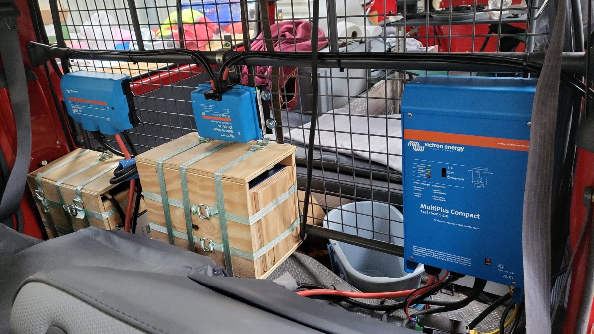
The installation is barely visible behind the seatsView from the back with preliminary wiringConnection of cell blocks with SB175 connectors, cell block 2 and DC-DC converterLynx Distributor with cell block 1Inverter/charger with space for second charger and cell block 2 (left)
Note: the Phoenix charger is not visible on the images, as I am still waiting for it to be delivered.
Charging via EVSE
Conclusion
We now have more than 7'000Wh of additional energy without losing any storage space for roughly 2'850 CHF/2’500 GBP (parts without labour). We can survive an extended weekend of 72h without recharging while still being able to enjoy amenities as using a coffee machine, heating and refrigerator. In case of longer periods of usage, we can recharge at any EVSE, or via shore power. And in emergencies, we can also charge via our Honda EU10i or via the alternator of the vehicle.
The battery is placed directly over the engine which helps in cold weather conditions to easily warm up the batteries to a chargeable level.
In our trailers and vehicles I prefer 24V 8s batteries, as the price-weight-power triangle of our Eve 280Ah cells is hard to match. With a gross weight of roughly 55kg we get a nominal “capacity” of 7168Wh. Even at a low cell voltage of 2.7V we can still get more than 2400W (3000VA) out of the battery. Exactly what a Victron MultiPlus-II 24/3000/70-32 (or any 3000VA inverter/charger for that matter) can deliver.
The Honda EU 10i has a sustained output of 900W which equates to roughly 3.9A at 230V. Now, this is not too interesting by itself.
However, the minimum AC current input of the MultiPlus is 3.6A. So, exactly within the range of the Honda EU 10i. A 5000VA inverter for example, would drain the generator with its minimum input of 4.6A+. And with its fuel tank capacity of 2.1l it runs nearly 4h on full load. Which in turn means, I can charge our 24V 8s battery about 50% without refueling.
Note: ideally we would charge it from 25% up to 75% SoC.
So, for me this generator is the ideal backup when I am away without any EV station nearby. With its 13kg and small form factor (and price) there is always a place in my vehicles where I can put it.
And as a side benefit: when I run the generator along with the inverter I can generate up to 3300W (or over 14A). That is: run my oven and boil potatoes at the same time …
And the generator even makes sense when combined with a Victron MultiPlus Compact 24/1600/40-16 (or its 12V counterpart). They are the smallest inverters/chargers in that power range. They strong enough to run a coffee machine or immersion water heater, but are not pwoerful enough to run a full 2000W appliance. However, in combination with the Honda, they just reach 2180W. Of course, charging a 24V 8s battery with a “Compact” device takes much longer, due to its smaller charger.
The other day, I received my Victron MultiPlus Compact 12/1600/70-16. One of the first steps to do upon commissioning was to update the firmware. In my case from v481 to v502.
With my Windows PC running the latest VictronConnect App and a MK3 to USB-C Interface, I connected to the MultiPlus and enabled the advanced settings by entering the infamous zzz password (which you officially can only get from an official Victron training or distributor or simply by searching the internet).
I was offered to install 2606502.vff to which I happily clicked OK. So it seemed, I was running on a new microcontroller with 230V (hence 26) and really had a MultiPlus Compact 12/1600 (06). But I did not know this at that time.
After a couple of seconds into the update process, the operation stopped by telling me something failed. And after a restart, the only thing I could see was the yellow LED constantly flashing as soon as power was connected to the device and regardless of the main switch position.
Victron MultiPlus Compact flashes yellow after failed firmware update
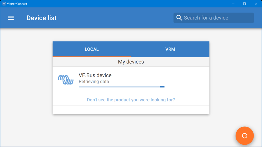
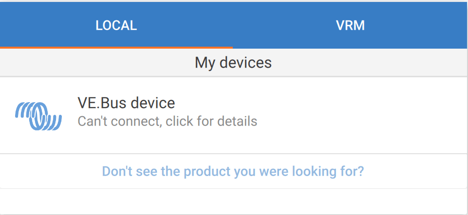
When I tried to reconnect with the VictronConnect app, the detection phase took very long – but the MultiPlus was not recognised.
VictronConnect trying to detect the MultiPlus after the failed firmware updateDetection unsuccessful after the failed firmware update
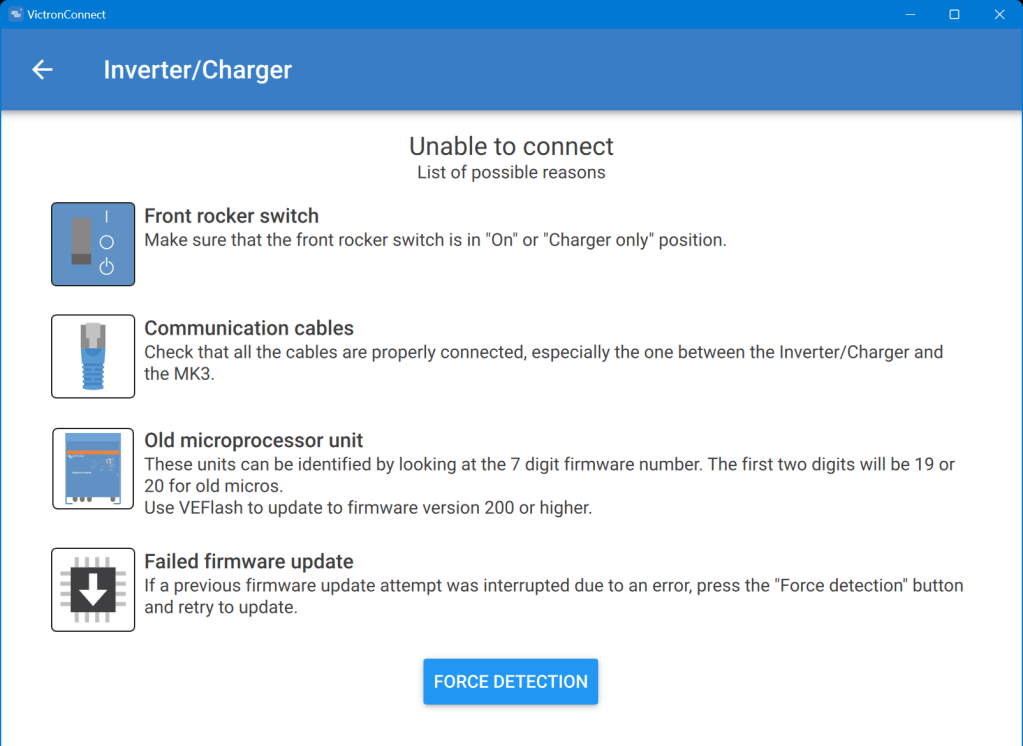
Even when I tried the “Force detection” option (which is intended to be used after a failed firmware update) no usable result was yielded.
“Force detection” did not work either
So, then I resorted to VEFlash (which is deprecated and has to be selected explicitly when installing the Victron tools on Windows).
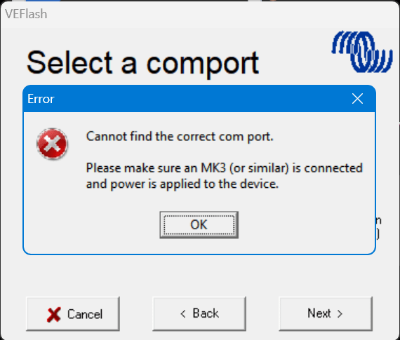
But this did not work either, as it could not find anything behind the MK3:
VEFlash failed to recognise the MultiPlus
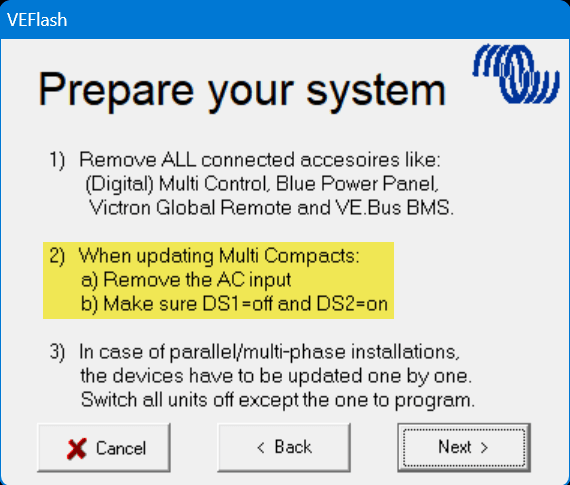
However, having a closer look at the hints VEFlash gave me before the recovery I was confused that VEFlash asked me to unplug the AC power source. How would I be able to update the firmware? Via DC? And why would it matter anyway which power source was connected?
VEFlash hint at not using AC power on a MultiPlus Compact
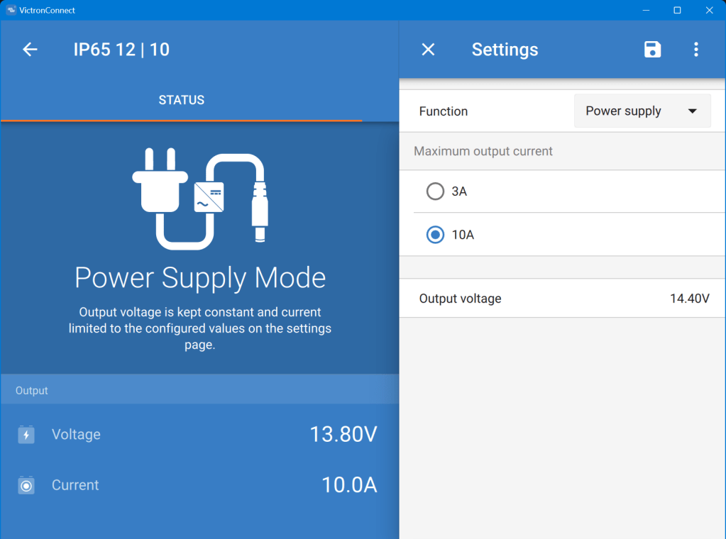
Using a Blue Smart Charger as a DC power source for the MultiPlus
As soon as I connected a Blue Smart IP65 Charger in “Power Supply” mode to it (and configured a voltage of 14.4V) the “Force detection” option in VictronConnect worked.
Note1: I did not alter any of the DIP switches as recommended by VEFlash.
With the next Toyota Hiace and the Saurer 2DM around the corner waiting to be converted, I thought it was time for consolidating our vehicular electrical installations.
But before going into details, some history first: In 2019, we started on the VW Calkifornia T6 with a Super B Epsilon 12V90Ah LiFePO4 battery as a simple drop-in replacement and added a Votronic SMI 1200 ST inverter to it. And this was probably where I made my first two mistakes. At that time, I decided for Votronic and against Victron Energy. And I did not pay attention to the non-existing programmability and extensibility features of the Votronic inverter.
Once with a vendor stick with that vendor? There a pros and cons to it as we will later see.
When we later prepared our Hilux for our first longer trip to Loch Watenan, I opted for a Liontron 12V200Ah battery again (for the reason Liontron being way cheaper than Super B). And for the inverter/charger, I went for Votronic again (SMI 1200 and the same DC-DC charger 1212-45) .
But when I tried to get the DC-DC charger working, I realised that the D+ signal was not available on the Hilux. All in all, I did not get it to work in any configuration and looked for alternatives – which came in the form of the Victron Orion-Tr Smart DC-DC Charger family. And when I had to add an AC charger (where in the Hymer I could use the existing AC charger) to load the Liontron battery “on-shore”, I chose the Victron Blue Smart IP22 Charger.
So, at that time there was some kind of tie between Victron and Votronic. And the setup was getting more complicated and more complicated. And I am not only talking about the diminishing space in the trunk of the Hilux.
If I had known about the Victron MultiPlus series at that time I could have saved me a lot of headaches and complications.
It was shortly after our first and very successful trip to Loch Watenan, when we got rid of the Hymer and I added the battery from it as a second battery to the Hilux. And I got 2 more Victron DC-DC chargers. But I sticked to my Votronic inverter. And this is how the final layout looked like:
Toyota Hilux setup with 2 Liontron 12V 200Ah batteries, 4 DC-DC 30A chargers
This all worked well end of 2021 when one of the Liontron batteries did not want to charge properly anymore. The combined cell voltage stayed low at 13.1V with no single cell near at 3.5V and the internal BMS still reported 100% SOC.
So it was time for a change. And while doing that eliminting some design shortcomings of the current installation:
Invertert has a power maximum of 1200W.
AC charging is limited 30A.
Both 200Ah batteries are operating separated with one of them feeding the inverter and the other feeding the 12V DC sources.
Each pair of DC-DC chargers is bound to a single battery.
The alternator cannot feed all 4 DC-DC but only 3 chargers at the same time.
Have both batteries run in parallel to feed the inverter and the DC sources at the same time and thus reducing the maximum current at 1300W to 65A (when both batteries are dropping down to the minimu of 4* 2.5V = 10V) or considerably lower when running at 14V (45A) .
But the “best” of it, I then got rid of all the Votronic devices and can integrate and configure more easily with Victron. And I can do the same in the Saurer and HiAce.
I hope I can start with the conversion mid of March and will post updates on the way.
So, what do you think? (And no, I have no affiliation with Victron at all.)
The Caravan we got last year did not come with an inverter, so getting coffee in the morning or running a microwave was only possible when our main generator was running. And the installed battery for 12V support had a rather small capacity. This was clear to us from the beginning, as we eventually wanted to connect the Caravan to our EVE 280Ah cells.
But since we got our Starlink internet and our router did not seem to run easily on DC power, we needed -in addition to the temporary morning AC coffee spike – a more permanent AC solution.
Of course, first I updated the firmware of the inverter and configured it work with the battery:
Setting the AC input to 16A
Setting the battery type to LiFePO4
Setting the charge current to 70A (which is over the recommend amount of 50A, but see below for details)
As I did not want to connect a Cerbo GX to the system, I just used the VictronConnect App. Maybe I add a VE.Bus Smart dongle later on, or I connect some GX nevertheless. Who knows … Until now, it needs a wired connection to the inverter to see its status.
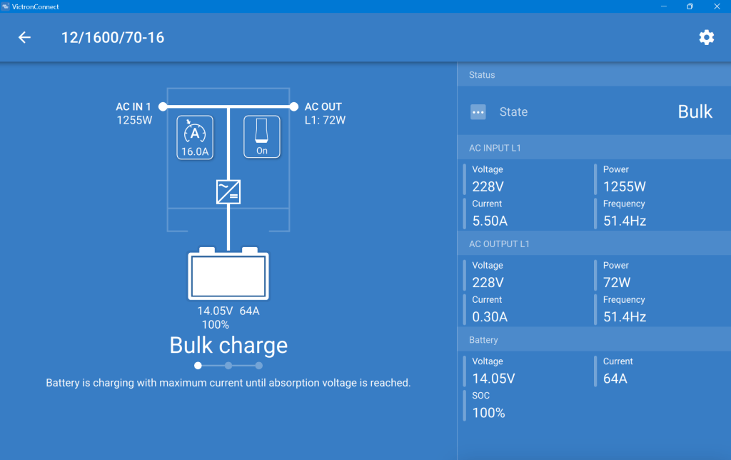
After powering on the generator, I confirmed everything was roughly working as expected. During the first run, the SOC was shown as 100% though the BMS of the battery internal saw it differently. In addition, the reported Amps and temperature were seen differently, as well. So, even that I set the inverter over the recommended maximum of 50A for the battery, the actual charge power was never much higher than the actual maximum).
This is what the inverter saw (100% SOC, 14.05V DC cell voltage, charging at 64A):
MultiPlus charging the Liontron battery via the generator
And this is, what the Liontron BMS reported (76% SOC, 13.8V DC cell voltage, charging at 55.5A):
The SOC as seen by the Liontron battery BMS
In the end, the BMS stopped charging when it thought its batteries were full. And the inverter did not complain. However, I noticed that the cells were really not in balance (with a delta of 200mV between the lowest and highest voltage).
Discharging was ok, as well. However, I soon realised that the 100A discharge current could not be achived in my setup. The inverter tried to draw power and the BMS cut off with a “Discharge over-current” (OCD). SO, still no coffee via our Nespresso machine (and no microwave either, for that matter).
So, what is the take away of all this?
It works and now, I can run the Internet all day.
All in all, it is a relatively simple and quick setup.
The Liontron battery does somehow not live up to its specs (and yes, I know the battery could be a size bigger for what I want to achieve; but I did not want to buy an additional battery for this temporary solution).
It is way cheaper and more flexible than to buy this “off the shelf”.
Maybe, I add a Victron SmartShunt to get a more accurate SOC reporting (as I do not see any other way to integrate the BMS with the inverter).
Charging of the battery is quite fast when running the generator.