I recently wrote about our upcoming solar PV adventure. But before updating our system, I thought it was time to document and explain our current setup (with the help of KiCad).
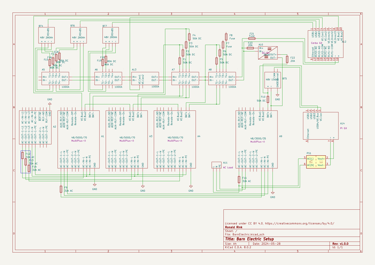
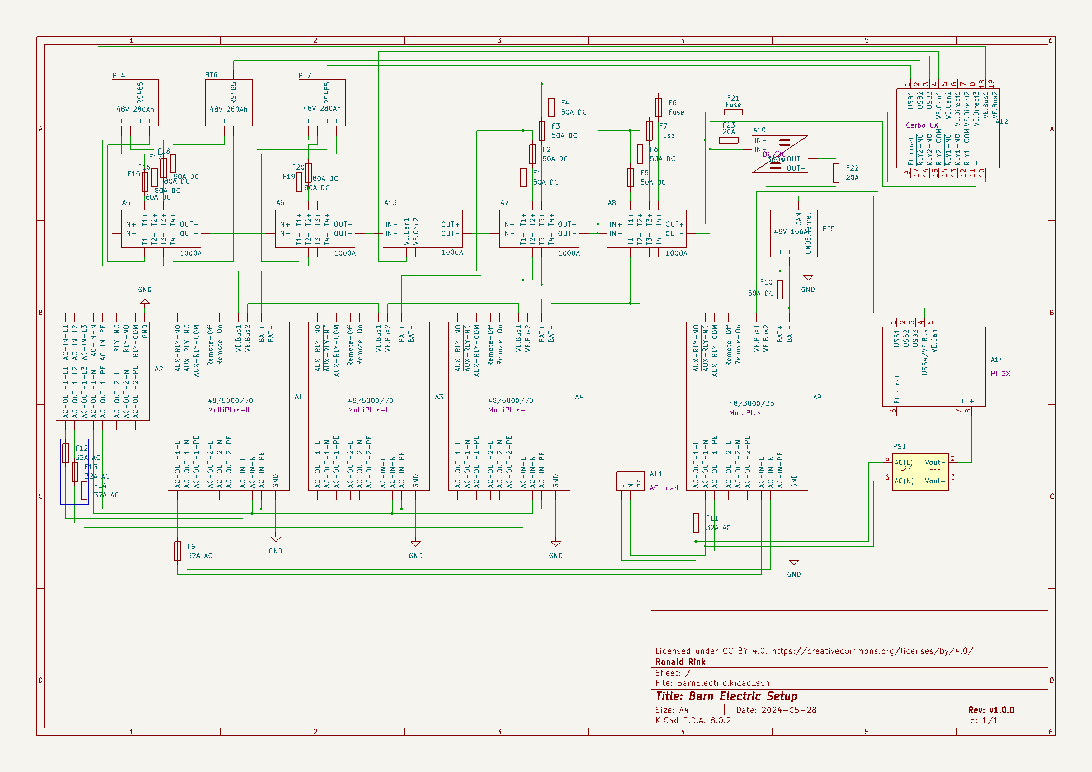
This system is the main electricity for our barn and currently consists of three batteries with an energy (often referred to as “capacity”) of 3* 14.33kWh = 43kWh (battery bank A, A1:A2 on the plan). These batteries are charged by a JCB G20QS (B1) via three MultiPlus-II 48/5000/70 inverters/chargers (B1:C2) which are by default in “Charge Only” mode. The MultiPlus-II are configured in a 3-phase configuration but only turned on when 3-phase is actually needed.
The main power is delivered by a MultiPlus-II 48/3000/35 (B4:C5) that is connected to a separate battery bank (battery bank B, BYD LVS Premium Battery-Box with an energy of 8kWh). This latter MultiPlus-II is connected to L1 of the 3-phase MultiPlus-II. So, whenever the main batteries get charged the cascaded inverter will also be charged. In addition, we can then use PowerAssist to up to supply 8'000VA (= 5'000VA + 3'000VA) when running on batteries and up to 14'500VA (= 6'500VA + 5'000VA + 3000VA) on a single phase.
Though the generator can supply up 14'400W the chargers of the Multiplus-II can only charge with a power of up to 3* 48V* 70A = 10'080W. This is actually an advantage as the optimal efficiency factor of the generator is roughly at 12'000W. So with 210A we are pretty close. If we ever added more chargers to the system we could even slightly increase the charge current to 250A.
System A with the 3-phase inverter configuration is connected to a Lynx bus bar (A1:B4) that also includes a Lynx shunt (B3) used for measuring over all batteries. In addition, there is an islolated Orion-Tr DC-DC charger (A5) that constantly feeds system B.
System A and B are connected to their separate GX:
system A Cerbo GX, A5:A6 MultiPlus-II via VE.Bus, Lynx Shunt via VE.Can, JK-BMS via RS485/USB
system B Raspberry Pi4running VenusOS, B5:B6 MultiPlus-II via VE.Bus, BYD BMS via VE.Can (on a Pi GPIO Hat)
And this is it for the electricity installation in our barn.
Note: This cascaded setup is officially not supported by Victron, but it has been working for us without problems for months now. This might be different in your case.
This is sort of a never ending story for me – just as the installation of our workshop container on the truck bed by our trusty mechanic which has been “in the making” since October 2022.
It is clear that we want and need electricity in the container. Just how and how much is not clear yet. In the following, I will consider our rquirements and different apsects and constraints of the electrical installation to hopefully come to a conclusion. This is a rather dry article with a lot of numbers – so beware …
Here is what we know (or at least think we know):
The truck has a 24V system
Charging any “leisure” batteries via the truck engine on a regular basis does not seem to be a good idea, as the fuel consumption is already 33l/100km without the container (that makes an astonishing 8.56mpg in the UK)
It is a EURO0diesel so we will not be able to get into all the cities (regardless of its problematic weight, length, height and width anyway).
Solar panels are still no real option (most of the time too way up in the North)
Charging from an EVSE might not always be possible as most of these EVSEs are for cars and do not have space for trucks
We want to be able to cook and wash in the vehicle
We will have a 2kWdiesel heater
We will have a 900W single phase petrol generator
We will be using Eve LF280K cells
The inverter must at least provide 2'250VA or 1'800W (concurrently, but not neccessarily on a single phase)
(optional) We would like to have 3-phase power in the container (as the cabling is already in place) – but also we know we would only use it very seldomly (such as for welding, then we need at least 11A per phase)
We would like to be able to charge 60% of the batteries (from 20% to 80%) within 3h
Refrigerator (able to run on 12V DC/24V DC or 230V AC)
Microwave (1'000W)
Water heater (immersion heater with 1'000W or 2'000W and/or kettle with 2'000W)
Table grill (1'250W)
Steam cooker (450W/900W)
Bread baking machine (600W)
Coffee machine (1'150W)
Washing machine (750W)
Water pressuriation system (850W)
Computers peripherals (USB-C charging with 36W via AC or DC, or 60W AC)
Lights (12V or 24V DC)
Water pump (12V or 24V DC)
Fan (12V or 24V DC)
Diesel heater (12V DC)
Starlink (60W AC, possibly 48V DC)
Infrared heating panel (150W AC)
Battery charger (12V/24V DC or 230V AC, depending on model)
Other USB powered and/or chargeable devices (via 12V/24V DC or separate 230V AC charger)
built-in 6t winch (powered by engine)
(optional) electric shower (8'000W)
Sizing the electrical installation comes with a number of additional constraints:
The crane in the workshop garage can lift up to 500kg this mean, all batteries, inverters, washine machine and water tanks must be less that weight
No single battery can charge or discharge with more than 140A
We can only charge from EVSEs with a Type 2 connector
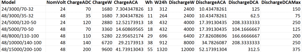
A 12V system is very quickly out of the picture (and the largest and only MultiPlus-II with 12V is a 3’000VA system). Besides, the truck has 24V system anyway. So it is either 24V or 48V. Here is an overview of all current 24V and 48V MultiPlus-II models and their charge and discharge values:
MultiPlus-II 24V and 48V
Let’s first evaluate a 24V system:
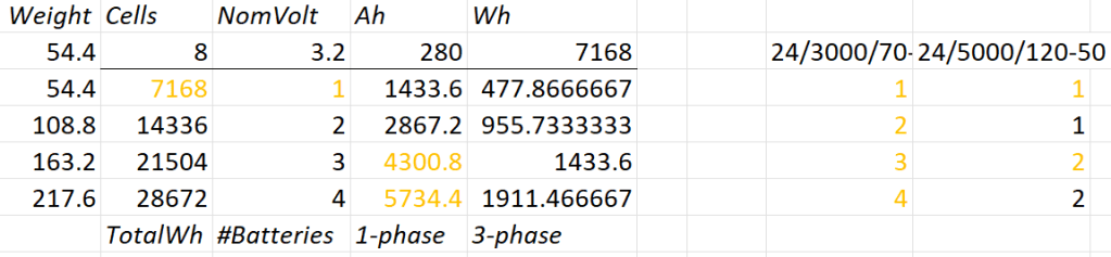
Combination of 24V batteries and invertes
1* 8s battery
Capacity is likely to be too small
Single battery is not redundant
1*3’000VA can draw too much discharge current
1* 5’000VA can draw too much discharge current
2* 8s battery
2* 3’000VA can draw too much discharge current
1* 5’000VA possible
3* 8s battery
1-phase charge requirement can only be met with EVSE 7kW 32A Type 2
3* 3’000VA can draw too much discharge current
2* 5’000VA can draw too much discharge current
4* 8s battery
1-phase charge requirement can only be met with EVSE 7kW 32A Type 2
4* 3’000VA can draw too much discharge current
So, in a 24V 1-phase system only the 5'000VA inverter would be possible with either 2 (14’336Wh) or 4 (28’673Wh) batteries.
For a 3-phase setup to support our Kemppi Kempact 253A we would need at least 4 batteries and 3* 5'000VA inverters.
And now let’s have a look at a 48V system where we have a couple of more inverter options:
Combination of 48V batteries and inverters
1* 16s battery
Single battery is not redundant
2* 3’000VA inverters needed
1* 5’000VA inverter possible
1* 8’000VA can draw too much discharge current
1* 10’000VA can draw too much discharge current
1* 15’000VA can draw too much discharge current
2* 16s battery
1-phase charge requirement can only be met with EVSE 7kW 32A Type 2
3’000VA not as 3-phase setup feasible (otherwise 6 devices necessary)
8’000VA only as 3-phase setup, but then too heavy
1* 10’000VA possible
1* 15’000VA can draw too much discharge current
3* 16s battery
1-phase charge requirement cannot be met
charge requirement can only be met with 3-phase EVSE (16A or 32A) Type 2 (11kW+)
3’000VA possible, but too heavy with combined battery weight
5’000VA possible
8’000VA only as 3-phase setup, but then too heavy
10’000VA only as 3-phase setup, but then too heavy
15’000VA possible
4* 16s battery
batteries too heavy
1-phase charge requirement cannot be met
charge requirement can only be met with 3-phase EVSE (16A or 32A) Type 2 (11kW+)
3’000VA too heavy with combined battery weight
5’000VA too heavy with combined battery weight
8’000VA only as 3-phase setup, but then too heavy
10’000VA only as 3-phase setup, but then too heavy
15’000VA only as 3-phase setup, but then too heavy
So, this leaves us with really 3+2 choices:
2* 8s (14’336Wh) batteries in a 1-phase system with a single 5’000VA inverter
Battery and inverters would weigh roughly 140kg
2* 8s (14’336Wh) batteries in a 3-phase system with three 5’000VA inverters
Battery and inverters would weigh roughly 250kg
Not possible for 3-phase welding
4* 8s (28’672Wh) batteries in a 3-phase system with three 5’000VA inverters
Battery and inverters would weigh roughly 310kg
1* 16s (14’336Wh) battery in a 1-phase system with a single 5’000VA inverter
Battery and inverter would weigh roughly 140kg
2* 16s (28’672Wh) batteries in a 3-phase system with three 5’000VA inverters
Battery and inverters would weigh roughly 310kg
3h on a 1-phase 16A Type 2 would charge about 38% (a 60% charge takes 4.7h)
From there, we can narrow this down even further:
1-phase system: 24V, 2*8s
Price: batteries 2* 1’364GBP = 2’728CHF plus inverter 1* 1’359GBP total = 4'087GBP
Con: 24V MultiPlus-II are considerably more expensive (than 48V)
Con: only have the capacity
Con: cannot run electric shower
3-phase system: 48V, 2* 16s
Price: batteries 4* 1’364GBP = 5’456CHF plus inverter 3* 812GBP = 2’436GBP total = 8'802GBP
Con: charge requirement can only be met with 32A Type2 on 1-phase
Con: additional 48V|24V DC-DC converter required
Con: heavier, 300kg+ Con: higher self-consumption in 3-phase configuration
So – drum roll – my conclusion: for roughly double the money in a 48V we would get double the capacity and triple the charge and output power and pretty much can do everything we want the system to be able to do.
The 3-phase system can be reconfigured to a parallel 1-phase system, so we would even be able to use an electric shower (though very unlikely – we have our mobile shower). We can either charge 1-phase or 3-phase and have a longer window of electric autarky. And for most of the time we would leave the system in a 1-phase single device InverterCharger configuration. And additionally, for charging the other 2 devices would bet set to ChargeOnly (but be configured independently configured from each other).
The exact setup I will have to layout some other time, but right out of my head I would think of the following components:
External power in with CEE 16-5, CEE32-5, CEE32-1, CEE16-1 and Neutrik PowerCON True1 TOP (the more the better) connected to an ATS
AC out from MultiPlus-II connected to ATS
Orion-Tr 24V|48V DC-DC converter charging from alternator (though not the norm)
Orion-Tr 48V|24V DC-DC converter as power supply: to support 24V loads in the container as charger: as an emergency charger for the truck batteries
Lynx Power In, Distributor
Venus OS with Raspberry PI for RS-486 and DVCC
So, in case our Saurer ever gets finished – at least I know how to do the electricity …
Now, that we got our Toyota HiAce we thought it might be a good idea to add more power to the vehicle: in form of an 8s EVE LF280K LiFePO4 battery and a Victron MultiPlus Compact 24/1600/40-16 inverter/charger. In the following, we describe our setup and the reason why we built it like this.
The Requirements
The sustained output power of the inverter must be over 1'200W.
Charging via AC via EVSE or generator must be possible.
Charging via alternator must be possible (but is not the norm).
Charging of 60% of the battery (from 20% – 80%) via AC should take less than 180min.
The installation should use the minimum amount of space possible.
We should be able to use our existing Eve LF280K cells, thus limiting the overall current to 140A.
As the vehicle will not have a diesel heater, it should be possible to run a 150W infrared heater for at least 3 * (4+2)h = 18h (^= 2'700Wh).
In addition, the battery should be able to run a refrigerator with an average power consumption of 50W for at least 72h ^= 3'600Wh (next to other power consumption).
Design Considerations
With a maximum current of 140A and a cable run length of 1.5m, we should plan with a cross section of at least 35mm2.
Basically, with Eve LF280K cells we have three choices regarding the battery size:
1* 4s (“12V”) Configuration 4 * 3.2V * 280Ah = 3'584Wh This would lead to a required nominal AC charge power of at least 716.8W/h and a charge current of at least 56A/h.
2* 4s (“12V”) Configuration 2* 4 * 3.2V * 280Ah = 7'168Wh This would lead to a required nominal AC charge power of at least 1'433.6W/h and a charge current of at least 112A/h.
1* 8s (“24V”) Configuration 8 * 3.2V * 280Ah = 7'168Wh This would lead to a required nominal AC charge power of at least 1'433.6W/h and a charge current of at least 56A/h.
The Victron MultiPlus Compact xx/1600VA inverter/charger provides enough sustained power output (while being smaller than the non-Compact edition). Depending on the voltage of the battery, this will slightly impact the amount of charge current.
To charge the battery via the alternator we would need a DC/DC converter that depends on the battery configuration as well (either 12-12 or 12-24). So, let’s have a look at the battery first.
1* 4s (“12V”) Configuration
The smallest, lightest and cheapest configuration. But capacity requirements regarding the fridge are only fulfilled, if there are no other loads. In addition, the discharge current is relatively high (scratching the maximum discharge rate of 0.5C).
2* 4s (“12V”) Configuration
More complex setup, as each battery needs a separate BMS, which leads to the need of an aggregator for both batteries to correctly report SoC and calculate CCL and DCL. In addition, more cabling and fusing is required (and probably to a large bus bar). Comes with the advantage of having a redundant battery in case a single battery fails. Most expensive configuration.
1* 8s (“24V”) Configuration
Custom battery build needed, as there is not enough space for a typical 2 * 4 cells setup behind he seats. But, only a single BMS and thus less wiring is needed. Comes with a slight disadvantage of not having native 12V from the battery. This is actually not an isse, as all our DC devices also accept 24V. Cells can better balance voltage differences across a single 8s bank.
The Setup
In the end, I decided for the 8s configuration, due to less complexity. Splitting the 8s configuration across two cell blocks seemed to be an acceptable compromise.
As a regular MultiPlus 24/1600/40-16 would not fulfill my AC charge requirements, I had to decide to either add a second MultiPlus or to add a dedicated charger. I opted for a Phoenix Smart IP43 Charger 24/25 instead of a second MultiPlus. The MultiPlus in parallel would always consume 10W though most of the time I would not need the output power. Whereas, the Phoenix would only need power, when connected to AC. And reconfiguring the MultiPlus every time I charge was not an option for me. And yes, I lose redundancy – but also save some money (Phoenix is much cheaper). So, in the end the nominal charge power is 40A + 25A = 65A, which lets me charge at 1'560W reaching 60% within 165min.
The HiAce comes with a 70A alternator, so I chose a Orion-Tr Smart 12/24-15 DC-DC Charger. With this charger, I could run the engine in standby and still have the car heater running. And this is probably the predominant use case (if charging via alternator at all).
For the DC bus bar I went for a Victron Lynx Distributor, so I could use and install MEGA fuses. Having a 1’000A bus bar seems certainly overkill, but a separate bus bar and fuse box that accepts 35mm2 cable and MEGA fuses would be not be much smaller.
I changed the existing AC inlet of the HiAce to Neutrik PowerCON True1 TOP (congrats to the marketing department, I am still amazed how this name rolls of the tongue) and installed 2 Siemens compact 16A CRCBOs (external AC in, internal AC out). I am aware that theoretically I could support more than 16A on the internal AC out (via PowerAssist). If ever needed, I can replace the RCBO with a 20A version.
I added a VE.Bus Smart Dongle to the MultiPlus and opted against a complete (Raspberry-based) GX installation. The reason, I keep a USBMK3 with me anyway (in case I need to reconfigure the MultiPlus) and still have (Bluetooth) access to the most important settings and information of the MultiPlus. With the GX, I would to be running a WiFi hotspot (and consuming more energy as well). The disadvanage of not being able to use DVCC with information from the BMS is clear to me and accepted.
I selected a B2A8S20P JK-BMS that has an integrated 2A balancer and an RS485, CAN and heat port. In case, I ever add a GX device, I am still able to connect them and use DVCC.
The Specs
Nominal power (“capacity”) 8 * 3.2V * 280Ah = 7'168Wh
Maximum discharge power 1’600VA (1'280W, capped by the inverter) with a maximum current of 80A/63A/55A (at 2.5V/3.2V/3.65V)
Maximum AC charge power 1'560W
AC Charging from 20% – 80% in 165min
Maximum DC charge power 360W
MultiPlus self-power consumption 10W
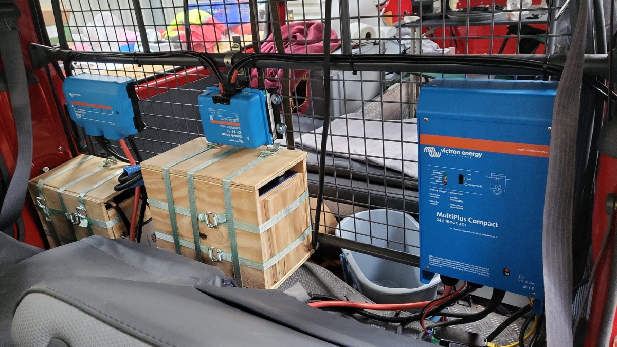
The Build
As mentioned before, due to space constraints I had to split the battery in 2 parts (with each having 4 cells). Instead of using utz RAKO boxes I used 12mm (sanded) plywood which I did not screw together but tied down with a banding/tensioning tool and a ratchet strap. With this setup, I can easily access und disassemble the cells if needed, while still having a sturdy case. Both cell blocks are connected with a (blue) Anderson SB175 connector.
The BMS itself is mounted to the side of one of the cases (I took extra care to use short screws, in order not to drill into the cell casing). I used M6 Weidmüller 35mm2 90° angled compression cable lug to get the wire away from the BMS and into the bus bar. All other compression cable lugs are DIN 46235 from Klauke (M6 35mm2 on the cells, and M8 16mm2/35mm2 on the bus bar).
The AC and DC wires are all Eland H07RN-F (except for the last two points):
Charger to bus bar, battery to bus bar: 35mm2
Cell block to cell block: 2 * 35mm2
Alternator to DC-DC converter, DC-DC converter to bus bar: 16mm2
External AC in to RCBO, RCBO to inverter/charger (both directions), RCBO to internal AC out: 3G2.5mm2
For the connection of the Inverter/charger to the bus bar, I used the Victron installed 25mm2 welding cables.
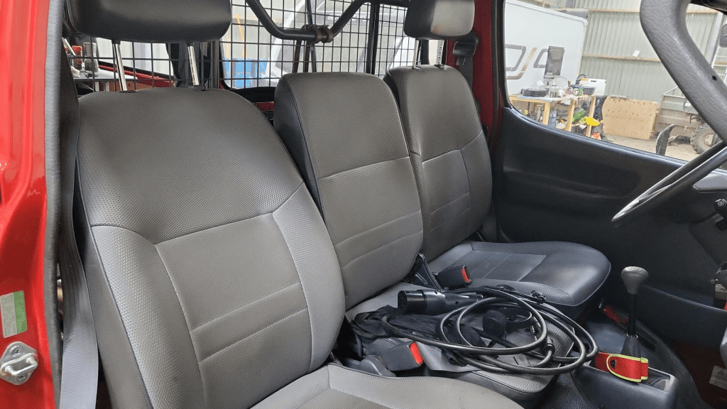
Images
The installation is barely visible behind the seatsView from the back with preliminary wiringConnection of cell blocks with SB175 connectors, cell block 2 and DC-DC converterLynx Distributor with cell block 1Inverter/charger with space for second charger and cell block 2 (left)
Note: the Phoenix charger is not visible on the images, as I am still waiting for it to be delivered.
Charging via EVSE
Conclusion
We now have more than 7'000Wh of additional energy without losing any storage space for roughly 2'850 CHF/2’500 GBP (parts without labour). We can survive an extended weekend of 72h without recharging while still being able to enjoy amenities as using a coffee machine, heating and refrigerator. In case of longer periods of usage, we can recharge at any EVSE, or via shore power. And in emergencies, we can also charge via our Honda EU10i or via the alternator of the vehicle.
The battery is placed directly over the engine which helps in cold weather conditions to easily warm up the batteries to a chargeable level.