I never actually measured the difference in internal resistance of the ones we built and some we got with our EVE LF280K cells. Time to correct this …
The flexible busbars delivered with our cells have approximately these dimensions: 105mm * 20mm * 2mm. This should give us a surface area of 40mm2 and an ideal internal resistance of around 0.045mOhm (according to some online calculators).
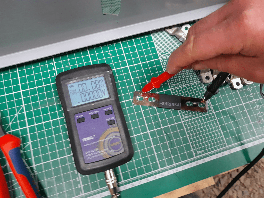
When measuring this with our trusty and highly precise TR1035+ the result displayed is 0.08mOhm.
Pre-built busbars 105mm * 20mm * 2mm
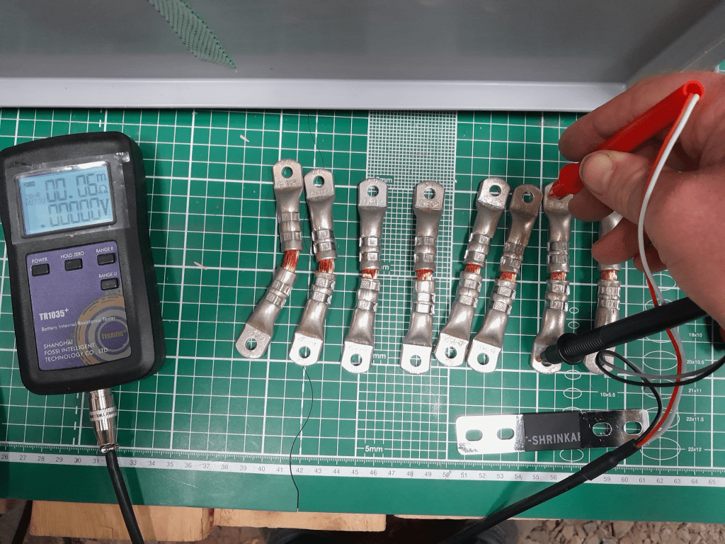
The Klauke version which comes with tinned copper lugs gives us a reading of 0.06mOhm – despite the smaller cross-section of 35mm2. The ideal internal resistance of the copper wire could be expected to be around 0.051mOhm (according to some other online calculator), so we are much closer to the measured value.
Custom busbar 105mm * 35mm2
The display error of the TR1035+ is expected to be similar as the measured range of both busbars is quite similar. There is certainly quite an amount of uncertainty (not only due to the maximum resolution of 10uOhm) to it. But it is interesting to see that the resistance of the custom busbars seems to be lower despite its smaller cross-section – while being better insulated (not seen on the picture) and more flexible at the same time (as it can be bent in more directions).
Producing these custom busbars is certainly more expensive (a single lug costs around 1.17GBP or 1.27CHF) and involves more manual and time consuming labour. However, it is quite easy to double them and/or increase its cross-section to up to 70mm2 per wire (when using multi-stranded DIN EN 60228 conductors).
So, this is it for today with fascinating facts about busbars for LiFePO4 cells.
Now, that we got our Toyota HiAce we thought it might be a good idea to add more power to the vehicle: in form of an 8s EVE LF280K LiFePO4 battery and a Victron MultiPlus Compact 24/1600/40-16 inverter/charger. In the following, we describe our setup and the reason why we built it like this.
The Requirements
The sustained output power of the inverter must be over 1'200W.
Charging via AC via EVSE or generator must be possible.
Charging via alternator must be possible (but is not the norm).
Charging of 60% of the battery (from 20% – 80%) via AC should take less than 180min.
The installation should use the minimum amount of space possible.
We should be able to use our existing Eve LF280K cells, thus limiting the overall current to 140A.
As the vehicle will not have a diesel heater, it should be possible to run a 150W infrared heater for at least 3 * (4+2)h = 18h (^= 2'700Wh).
In addition, the battery should be able to run a refrigerator with an average power consumption of 50W for at least 72h ^= 3'600Wh (next to other power consumption).
Design Considerations
With a maximum current of 140A and a cable run length of 1.5m, we should plan with a cross section of at least 35mm2.
Basically, with Eve LF280K cells we have three choices regarding the battery size:
1* 4s (“12V”) Configuration 4 * 3.2V * 280Ah = 3'584Wh This would lead to a required nominal AC charge power of at least 716.8W/h and a charge current of at least 56A/h.
2* 4s (“12V”) Configuration 2* 4 * 3.2V * 280Ah = 7'168Wh This would lead to a required nominal AC charge power of at least 1'433.6W/h and a charge current of at least 112A/h.
1* 8s (“24V”) Configuration 8 * 3.2V * 280Ah = 7'168Wh This would lead to a required nominal AC charge power of at least 1'433.6W/h and a charge current of at least 56A/h.
The Victron MultiPlus Compact xx/1600VA inverter/charger provides enough sustained power output (while being smaller than the non-Compact edition). Depending on the voltage of the battery, this will slightly impact the amount of charge current.
To charge the battery via the alternator we would need a DC/DC converter that depends on the battery configuration as well (either 12-12 or 12-24). So, let’s have a look at the battery first.
1* 4s (“12V”) Configuration
The smallest, lightest and cheapest configuration. But capacity requirements regarding the fridge are only fulfilled, if there are no other loads. In addition, the discharge current is relatively high (scratching the maximum discharge rate of 0.5C).
2* 4s (“12V”) Configuration
More complex setup, as each battery needs a separate BMS, which leads to the need of an aggregator for both batteries to correctly report SoC and calculate CCL and DCL. In addition, more cabling and fusing is required (and probably to a large bus bar). Comes with the advantage of having a redundant battery in case a single battery fails. Most expensive configuration.
1* 8s (“24V”) Configuration
Custom battery build needed, as there is not enough space for a typical 2 * 4 cells setup behind he seats. But, only a single BMS and thus less wiring is needed. Comes with a slight disadvantage of not having native 12V from the battery. This is actually not an isse, as all our DC devices also accept 24V. Cells can better balance voltage differences across a single 8s bank.
The Setup
In the end, I decided for the 8s configuration, due to less complexity. Splitting the 8s configuration across two cell blocks seemed to be an acceptable compromise.
As a regular MultiPlus 24/1600/40-16 would not fulfill my AC charge requirements, I had to decide to either add a second MultiPlus or to add a dedicated charger. I opted for a Phoenix Smart IP43 Charger 24/25 instead of a second MultiPlus. The MultiPlus in parallel would always consume 10W though most of the time I would not need the output power. Whereas, the Phoenix would only need power, when connected to AC. And reconfiguring the MultiPlus every time I charge was not an option for me. And yes, I lose redundancy – but also save some money (Phoenix is much cheaper). So, in the end the nominal charge power is 40A + 25A = 65A, which lets me charge at 1'560W reaching 60% within 165min.
The HiAce comes with a 70A alternator, so I chose a Orion-Tr Smart 12/24-15 DC-DC Charger. With this charger, I could run the engine in standby and still have the car heater running. And this is probably the predominant use case (if charging via alternator at all).
For the DC bus bar I went for a Victron Lynx Distributor, so I could use and install MEGA fuses. Having a 1’000A bus bar seems certainly overkill, but a separate bus bar and fuse box that accepts 35mm2 cable and MEGA fuses would be not be much smaller.
I changed the existing AC inlet of the HiAce to Neutrik PowerCON True1 TOP (congrats to the marketing department, I am still amazed how this name rolls of the tongue) and installed 2 Siemens compact 16A CRCBOs (external AC in, internal AC out). I am aware that theoretically I could support more than 16A on the internal AC out (via PowerAssist). If ever needed, I can replace the RCBO with a 20A version.
I added a VE.Bus Smart Dongle to the MultiPlus and opted against a complete (Raspberry-based) GX installation. The reason, I keep a USBMK3 with me anyway (in case I need to reconfigure the MultiPlus) and still have (Bluetooth) access to the most important settings and information of the MultiPlus. With the GX, I would to be running a WiFi hotspot (and consuming more energy as well). The disadvanage of not being able to use DVCC with information from the BMS is clear to me and accepted.
I selected a B2A8S20P JK-BMS that has an integrated 2A balancer and an RS485, CAN and heat port. In case, I ever add a GX device, I am still able to connect them and use DVCC.
The Specs
Nominal power (“capacity”) 8 * 3.2V * 280Ah = 7'168Wh
Maximum discharge power 1’600VA (1'280W, capped by the inverter) with a maximum current of 80A/63A/55A (at 2.5V/3.2V/3.65V)
Maximum AC charge power 1'560W
AC Charging from 20% – 80% in 165min
Maximum DC charge power 360W
MultiPlus self-power consumption 10W
The Build
As mentioned before, due to space constraints I had to split the battery in 2 parts (with each having 4 cells). Instead of using utz RAKO boxes I used 12mm (sanded) plywood which I did not screw together but tied down with a banding/tensioning tool and a ratchet strap. With this setup, I can easily access und disassemble the cells if needed, while still having a sturdy case. Both cell blocks are connected with a (blue) Anderson SB175 connector.
The BMS itself is mounted to the side of one of the cases (I took extra care to use short screws, in order not to drill into the cell casing). I used M6 Weidmüller 35mm2 90° angled compression cable lug to get the wire away from the BMS and into the bus bar. All other compression cable lugs are DIN 46235 from Klauke (M6 35mm2 on the cells, and M8 16mm2/35mm2 on the bus bar).
The AC and DC wires are all Eland H07RN-F (except for the last two points):
Charger to bus bar, battery to bus bar: 35mm2
Cell block to cell block: 2 * 35mm2
Alternator to DC-DC converter, DC-DC converter to bus bar: 16mm2
External AC in to RCBO, RCBO to inverter/charger (both directions), RCBO to internal AC out: 3G2.5mm2
For the connection of the Inverter/charger to the bus bar, I used the Victron installed 25mm2 welding cables.
Images
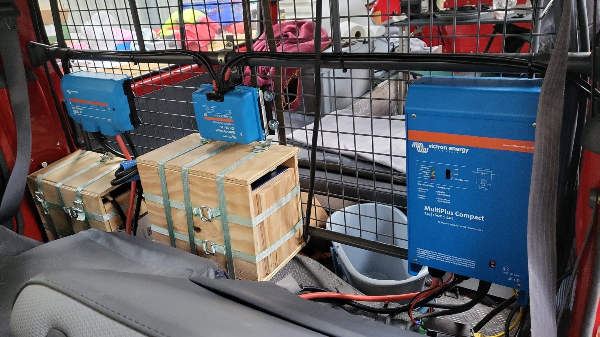
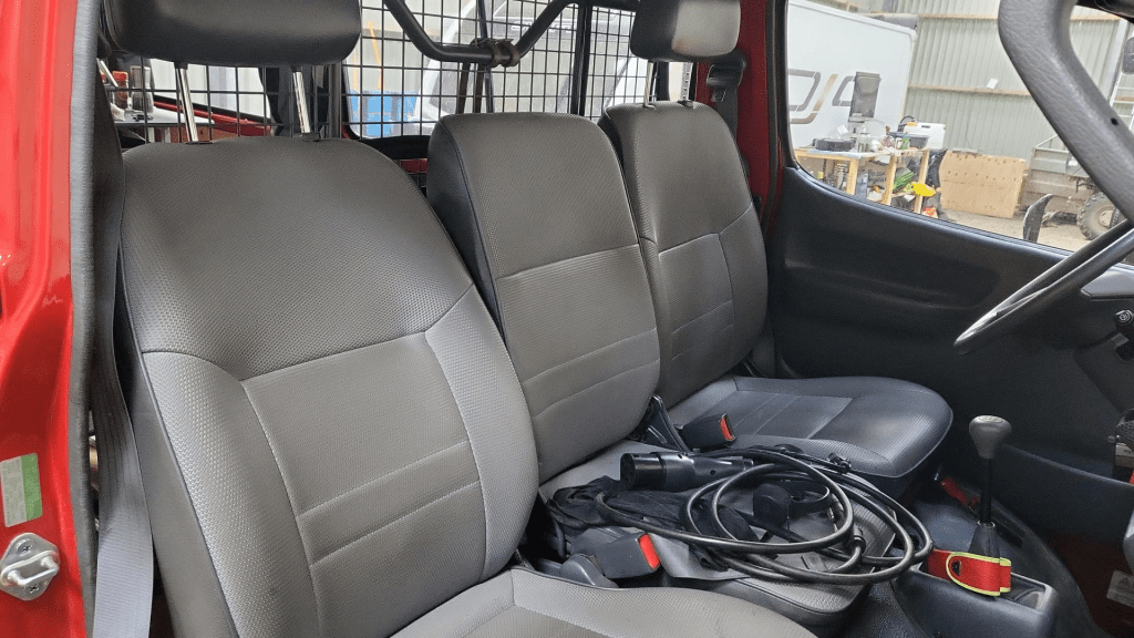
The installation is barely visible behind the seatsView from the back with preliminary wiringConnection of cell blocks with SB175 connectors, cell block 2 and DC-DC converterLynx Distributor with cell block 1Inverter/charger with space for second charger and cell block 2 (left)
Note: the Phoenix charger is not visible on the images, as I am still waiting for it to be delivered.
Charging via EVSE
Conclusion
We now have more than 7'000Wh of additional energy without losing any storage space for roughly 2'850 CHF/2’500 GBP (parts without labour). We can survive an extended weekend of 72h without recharging while still being able to enjoy amenities as using a coffee machine, heating and refrigerator. In case of longer periods of usage, we can recharge at any EVSE, or via shore power. And in emergencies, we can also charge via our Honda EU10i or via the alternator of the vehicle.
The battery is placed directly over the engine which helps in cold weather conditions to easily warm up the batteries to a chargeable level.
Top balancing is a topic where a lot of people have written about – and now it is my turn …
It is common understanding to use a regular charger when top balancing, and one the one hand set the Charge Voltage Limit (CVL) to cellCount * 3.65V and use a reasonable current and wait for an extended period of time until all cells have reached their cell voltage maximum. And reasonable means to use a current where the BMS balancer keep up with and distribute the Amps across the cells without going into a Overvoltage (OVP) for a single cell.
So, instead of using a charger with a high supported current of at least 20A we now can use our regular Victron MultiPlus-II inverter/charger – with the help of Venus OS.
The reason why we cannot use a Victron MultiPlus-II out of the box as a charger is the fact, that is does not support fixed Amp configurations (only maximums). And after a while at a specific voltage the MultiPlus-II would enter Absorption phase and thereby reducing the current over time and stopp charging after a while altogether.
So with the help of a custom service (or Python script based on the dummyservice) we can create a battery monitor and set a fixed current.
I am not going into details on how to get a Venus OS device (Victron Cerbo GX or Raspberry Pi) up and running. There is plenty of information on the internet. Or have a look at this article where I briefly describe the setup of a Pi for our BYD battery system.
The *service* itself can be run from a shell: /data/VirtualBatteryMonitor/VirtualBatteryMonitor.py (I copied the script into /data to survive a firmware update).
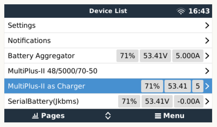
And then the service should appear in the “Device List”:
Our service as a device to support a constant charge current
There are two more configuration entries needed:
Enable our service as “Battery Monitor” (Settings, System setup, Battery Monitor)
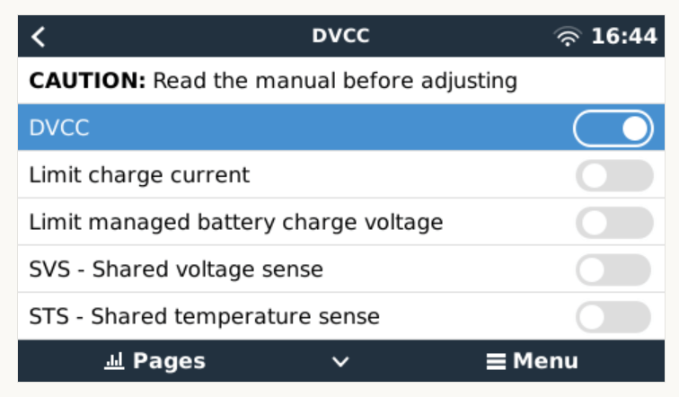
Our service configured as a “Battery Monitor”Enable DVCC
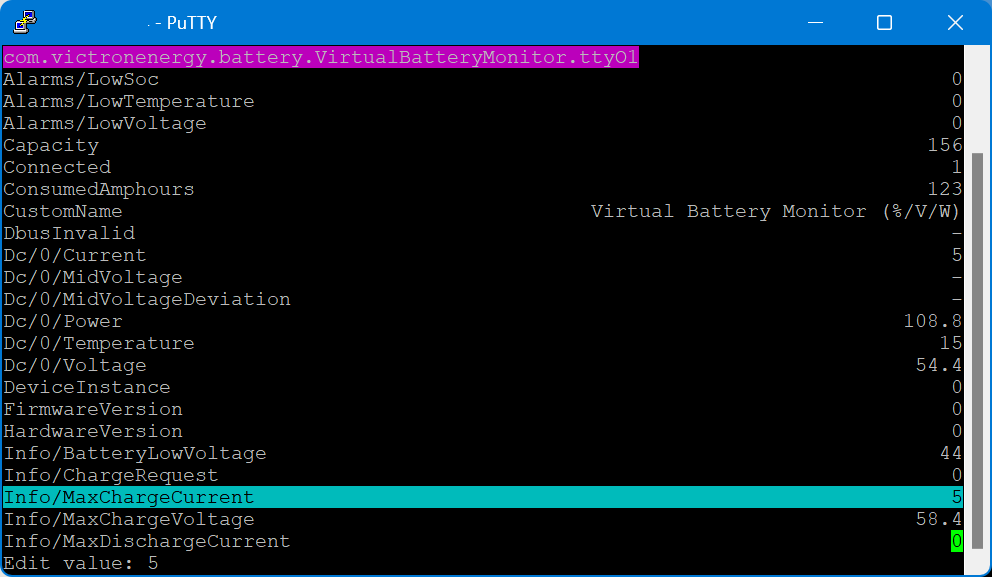
The actual parameters (charge current and maximum voltage) can be configured via dbus-spy from a shell:
Service parameters as shown by dbus-spy
The actually configured values are then shown under “Parameters” of the service (Service, Parameters):
Current configuration set to 5A constant charge current
Note1: There is no need for an actual integration of the BMS with the Venus OS.
Note2: Use at your own risk. Misconfiguring could potentionally harm the BMS, the battery or both.
Note3: Do not leave the script running / the battery charging unattendedly.
#!/usr/bin/env python3

"""
A class to put a simple service on the dbus, according to victron standards, with constantly updating
paths. See example usage below. It is used to generate dummy data for other processes that rely on the
dbus. See files in dbus_vebus_to_pvinverter/test and dbus_vrm/test for other usage examples.

To change a value while testing, without stopping your dummy script and changing its initial value, write
to the dummy data via the dbus. See example.

https://github.com/victronenergy/dbus_vebus_to_pvinverter/tree/master/test
"""
from gi.repository import GLib
import platform
import argparse
import logging
import sys
import os
import dbus
import os

# our own packages
sys.path.insert(1, os.path.join(os.path.dirname(__file__), "../ext/velib_python"))
sys.path.insert(1, "/opt/victronenergy/dbus-systemcalc-py/ext/velib_python")
from vedbus import VeDbusService
from vedbus import VeDbusItemImport

class VirtualBatteryMonitor(object):
    def __init__(
        self,
        servicename,
        deviceinstance,
        paths,
        productname="MultiPlus Charger",
        connection="dbus",
    ):

        try:
            # Connect to the sessionbus. Note that on ccgx we use systembus instead.
            logging.debug("Opening SystemBus ...")
            dbusConn = dbus.SystemBus()
            logging.info("Opening SystemBus SUCCEEDED.")
        except:
            logging.error("Reading system SOC FAILED.")

        logging.debug("Opening dbus '%s' ...", servicename)
        self._dbusservice = VeDbusService(servicename)
        logging.info("Opening dbus '%s' SUCCEEDED.", servicename)
        self._paths = paths

        logging.debug("%s /DeviceInstance = %d" % (servicename, deviceinstance))

        # Create the management objects, as specified in the ccgx dbus-api document
        self._dbusservice.add_path("/Mgmt/ProcessName", __file__)
        self._dbusservice.add_path("/Mgmt/ProcessVersion", "Unkown version, and running on Python " + platform.python_version())
        self._dbusservice.add_path("/Mgmt/Connection", connection)

        # Create the mandatory objects
        self._dbusservice.add_path("/DeviceInstance", deviceinstance)
        self._dbusservice.add_path("/ProductId", 0)
        self._dbusservice.add_path("/ProductName", productname)
        self._dbusservice.add_path("/FirmwareVersion", 0)
        self._dbusservice.add_path("/HardwareVersion", 0)
        self._dbusservice.add_path("/Connected", 1)

        # Create all the objects that we want to export to the dbus
        self._dbusservice.add_path('/Dc/0/Voltage', 3.4 * 16, writeable=True)
        self._dbusservice.add_path('/Dc/0/Current', 5, writeable=True)
        self._dbusservice.add_path('/Dc/0/Power', 3.4 * 16 * 2, writeable=True)
        self._dbusservice.add_path('/Dc/0/Temperature', 15, writeable=True)
        self._dbusservice.add_path('/Dc/0/MidVoltage', None)
        self._dbusservice.add_path('/Dc/0/MidVoltageDeviation', None)
        self._dbusservice.add_path('/ConsumedAmphours', 123, writeable=True)
        self._dbusservice.add_path('/Soc', 75, writeable=True)
        self._dbusservice.add_path('/TimeToGo', None)
        self._dbusservice.add_path('/Info/MaxChargeCurrent', 5, writeable=True)
        self._dbusservice.add_path('/Info/MaxDischargeCurrent', 0, writeable=True)
        self._dbusservice.add_path('/Info/MaxChargeVoltage', 3.65 * 16, writeable=True)

        self._dbusservice.add_path('/Info/BatteryLowVoltage', 2.75 * 16, writeable=True)
        self._dbusservice.add_path('/Info/ChargeRequest', False, writeable=True)
        self._dbusservice.add_path('/Alarms/LowVoltage', 0, writeable=True)
        self._dbusservice.add_path('/Alarms/HighVoltage', 0, writeable=True)
        self._dbusservice.add_path('/Alarms/LowSoc', 0, writeable=True)
        self._dbusservice.add_path('/Alarms/HighCurrent', 0, writeable=True)
        self._dbusservice.add_path('/Alarms/LowCellVoltage', 0, writeable=True)
        self._dbusservice.add_path('/Alarms/LowTemperature', 0, writeable=True)
        self._dbusservice.add_path('/Alarms/HighTemperature', 0, writeable=True)

        self._dbusservice.add_path('/Capacity', 156, writeable=True)
        self._dbusservice.add_path('/CustomName', "Virtual Battery Monitor (%/V/W)", writeable=True)
        self._dbusservice.add_path('/InstalledCapacity', 280, writeable=True)

        self._dbusservice.add_path('/System/MaxCellTemperature', 15, writeable=True)
        self._dbusservice.add_path('/System/MaxCellVoltage', 3.4, writeable=True)
        self._dbusservice.add_path('/System/MaxTemperatureCellId', "C5", writeable=True)
        self._dbusservice.add_path('/System/MaxVoltageCellId', "C2", writeable=True)
        self._dbusservice.add_path('/System/MinCellTemperature', 15, writeable=True)
        self._dbusservice.add_path('/System/MinCellVoltage', 3.4, writeable=True)
        self._dbusservice.add_path('/System/MinTemperatureCellId', "C6", writeable=True)
        self._dbusservice.add_path('/System/MinVoltageCellId', "C3", writeable=True)
        self._dbusservice.add_path('/System/NrOfCellsPerBattery', 16, writeable=True)
        self._dbusservice.add_path('/System/NrOfModulesBlockingCharge', 0, writeable=True)
        self._dbusservice.add_path('/System/NrOfModulesBlockingDischarge', 0, writeable=True)
        self._dbusservice.add_path('/System/NrOfModulesOffline', 0, writeable=True)
        self._dbusservice.add_path('/System/NrOfModulesOnline', 1, writeable=True)
        self._dbusservice.add_path('/System/Temperature1', 15, writeable=True)
        self._dbusservice.add_path('/System/Temperature2', 15, writeable=True)
        self._dbusservice.add_path('/System/Temperature3', 0)
        self._dbusservice.add_path('/System/Temperature4', 0)

# === All code below is to simply run it from the commandline for debugging purposes ===

# It will created a dbus service called com.victronenergy.pvinverter.output.
# To try this on commandline, start this program in one terminal, and try these commands
# from another terminal:
# dbus com.victronenergy.pvinverter.output
# dbus com.victronenergy.pvinverter.output /Ac/Energy/Forward GetValue
# dbus com.victronenergy.pvinverter.output /Ac/Energy/Forward SetValue %20
#
# Above examples use this dbus client: http://code.google.com/p/dbus-tools/wiki/DBusCli
# See their manual to explain the % in %20


def main():
    logging.basicConfig(level=logging.DEBUG)

    from dbus.mainloop.glib import DBusGMainLoop

    # Have a mainloop, so we can send/receive asynchronous calls to and from dbus
    DBusGMainLoop(set_as_default=True)

    pvac_output = VirtualBatteryMonitor(
        servicename="com.victronenergy.battery.VirtualBatteryMonitor.ttyO1",
        deviceinstance=0,
        paths={
            "/Ac/Energy/Forward": {"initial": 0, "update": 1},
            "/Position": {"initial": 0, "update": 0},
            "/Nonupdatingvalue/UseForTestingWritesForExample": {"initial": None},
            "/DbusInvalid": {"initial": None},
        },
    )

    logging.info(
        "Connected to dbus, and switching over to GLib.MainLoop() (= event based)"
    )
    mainloop = GLib.MainLoop()
    mainloop.run()


if __name__ == "__main__":
    main()
For my use case, this really helps as now I have a powerful charging (3 * Victron MultiPlus-II 48/5000/70-32 in parallel) that can charge the battery initally with 140A+ and later with smaller and smaller currents until all cells have reached their maximum voltage.
With the next Toyota Hiace and the Saurer 2DM around the corner waiting to be converted, I thought it was time for consolidating our vehicular electrical installations.
But before going into details, some history first: In 2019, we started on the VW Calkifornia T6 with a Super B Epsilon 12V90Ah LiFePO4 battery as a simple drop-in replacement and added a Votronic SMI 1200 ST inverter to it. And this was probably where I made my first two mistakes. At that time, I decided for Votronic and against Victron Energy. And I did not pay attention to the non-existing programmability and extensibility features of the Votronic inverter.
Once with a vendor stick with that vendor? There a pros and cons to it as we will later see.
When we later prepared our Hilux for our first longer trip to Loch Watenan, I opted for a Liontron 12V200Ah battery again (for the reason Liontron being way cheaper than Super B). And for the inverter/charger, I went for Votronic again (SMI 1200 and the same DC-DC charger 1212-45) .
But when I tried to get the DC-DC charger working, I realised that the D+ signal was not available on the Hilux. All in all, I did not get it to work in any configuration and looked for alternatives – which came in the form of the Victron Orion-Tr Smart DC-DC Charger family. And when I had to add an AC charger (where in the Hymer I could use the existing AC charger) to load the Liontron battery “on-shore”, I chose the Victron Blue Smart IP22 Charger.
So, at that time there was some kind of tie between Victron and Votronic. And the setup was getting more complicated and more complicated. And I am not only talking about the diminishing space in the trunk of the Hilux.
If I had known about the Victron MultiPlus series at that time I could have saved me a lot of headaches and complications.
It was shortly after our first and very successful trip to Loch Watenan, when we got rid of the Hymer and I added the battery from it as a second battery to the Hilux. And I got 2 more Victron DC-DC chargers. But I sticked to my Votronic inverter. And this is how the final layout looked like:
Toyota Hilux setup with 2 Liontron 12V 200Ah batteries, 4 DC-DC 30A chargers
This all worked well end of 2021 when one of the Liontron batteries did not want to charge properly anymore. The combined cell voltage stayed low at 13.1V with no single cell near at 3.5V and the internal BMS still reported 100% SOC.
So it was time for a change. And while doing that eliminting some design shortcomings of the current installation:
Invertert has a power maximum of 1200W.
AC charging is limited 30A.
Both 200Ah batteries are operating separated with one of them feeding the inverter and the other feeding the 12V DC sources.
Each pair of DC-DC chargers is bound to a single battery.
The alternator cannot feed all 4 DC-DC but only 3 chargers at the same time.
Have both batteries run in parallel to feed the inverter and the DC sources at the same time and thus reducing the maximum current at 1300W to 65A (when both batteries are dropping down to the minimu of 4* 2.5V = 10V) or considerably lower when running at 14V (45A) .
But the “best” of it, I then got rid of all the Votronic devices and can integrate and configure more easily with Victron. And I can do the same in the Saurer and HiAce.
I hope I can start with the conversion mid of March and will post updates on the way.
So, what do you think? (And no, I have no affiliation with Victron at all.)
The Caravan we got last year did not come with an inverter, so getting coffee in the morning or running a microwave was only possible when our main generator was running. And the installed battery for 12V support had a rather small capacity. This was clear to us from the beginning, as we eventually wanted to connect the Caravan to our EVE 280Ah cells.
But since we got our Starlink internet and our router did not seem to run easily on DC power, we needed -in addition to the temporary morning AC coffee spike – a more permanent AC solution.
Of course, first I updated the firmware of the inverter and configured it work with the battery:
Setting the AC input to 16A
Setting the battery type to LiFePO4
Setting the charge current to 70A (which is over the recommend amount of 50A, but see below for details)
As I did not want to connect a Cerbo GX to the system, I just used the VictronConnect App. Maybe I add a VE.Bus Smart dongle later on, or I connect some GX nevertheless. Who knows … Until now, it needs a wired connection to the inverter to see its status.
After powering on the generator, I confirmed everything was roughly working as expected. During the first run, the SOC was shown as 100% though the BMS of the battery internal saw it differently. In addition, the reported Amps and temperature were seen differently, as well. So, even that I set the inverter over the recommended maximum of 50A for the battery, the actual charge power was never much higher than the actual maximum).
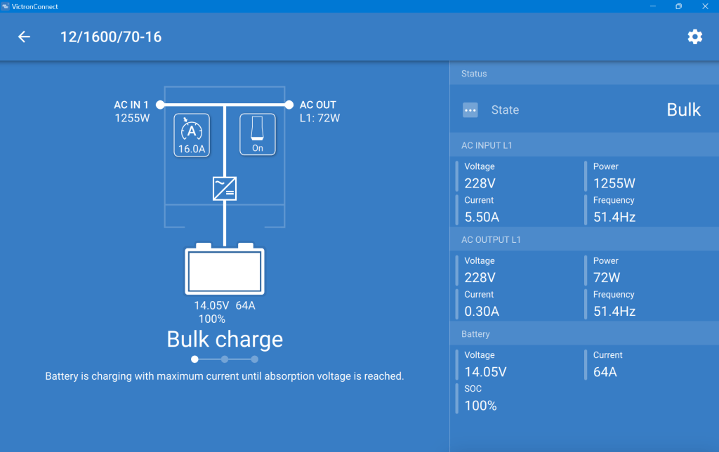
This is what the inverter saw (100% SOC, 14.05V DC cell voltage, charging at 64A):
MultiPlus charging the Liontron battery via the generator
And this is, what the Liontron BMS reported (76% SOC, 13.8V DC cell voltage, charging at 55.5A):
The SOC as seen by the Liontron battery BMS
In the end, the BMS stopped charging when it thought its batteries were full. And the inverter did not complain. However, I noticed that the cells were really not in balance (with a delta of 200mV between the lowest and highest voltage).
Discharging was ok, as well. However, I soon realised that the 100A discharge current could not be achived in my setup. The inverter tried to draw power and the BMS cut off with a “Discharge over-current” (OCD). SO, still no coffee via our Nespresso machine (and no microwave either, for that matter).
So, what is the take away of all this?
It works and now, I can run the Internet all day.
All in all, it is a relatively simple and quick setup.
The Liontron battery does somehow not live up to its specs (and yes, I know the battery could be a size bigger for what I want to achieve; but I did not want to buy an additional battery for this temporary solution).
It is way cheaper and more flexible than to buy this “off the shelf”.
Maybe, I add a Victron SmartShunt to get a more accurate SOC reporting (as I do not see any other way to integrate the BMS with the inverter).
Charging of the battery is quite fast when running the generator.