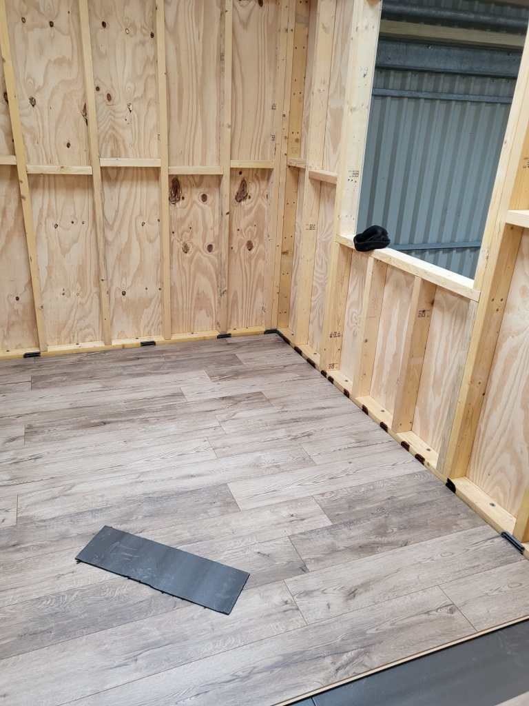
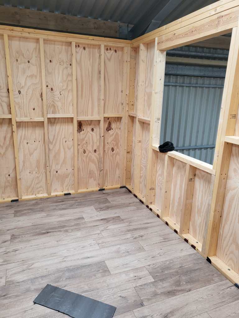
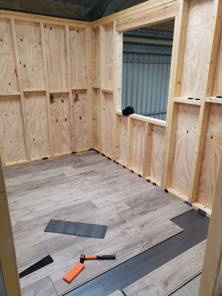
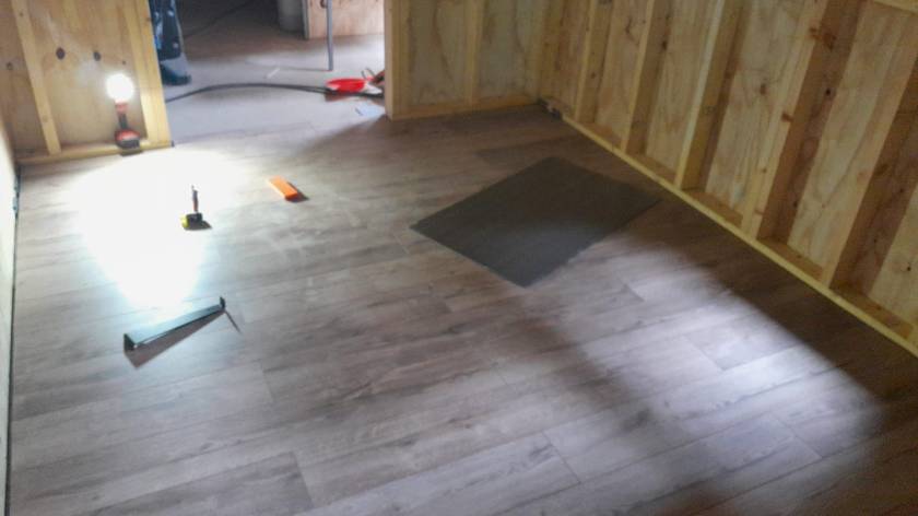
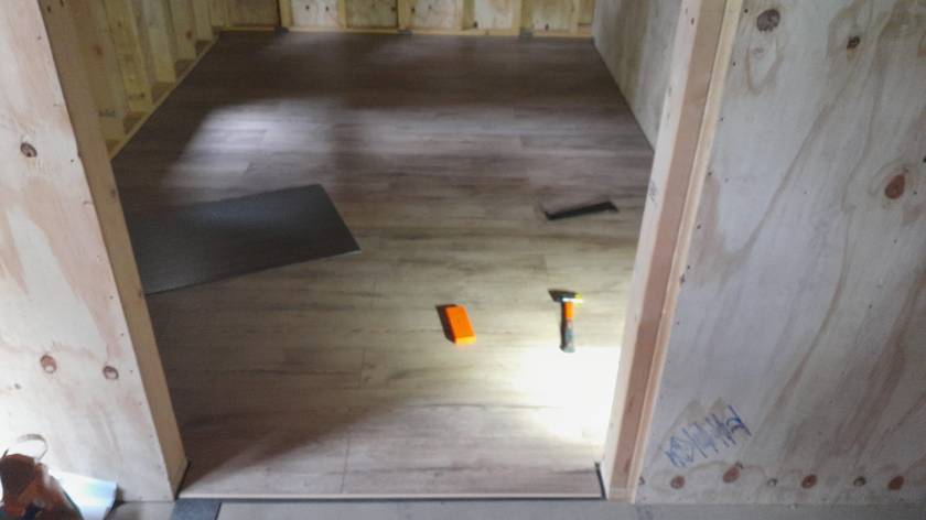
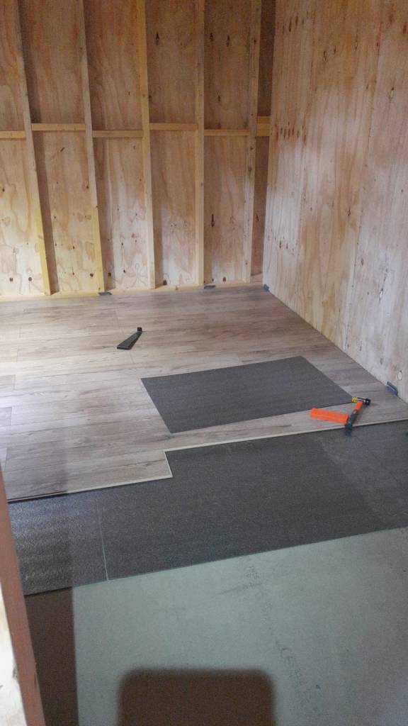
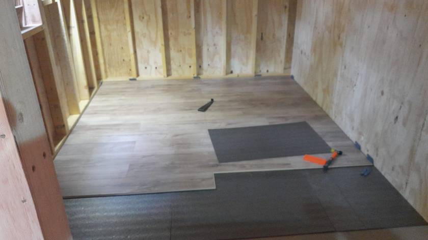
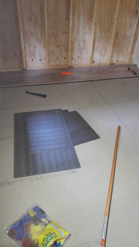
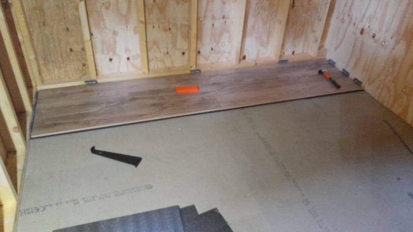
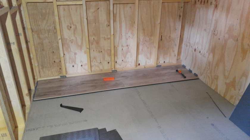
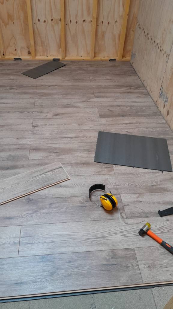
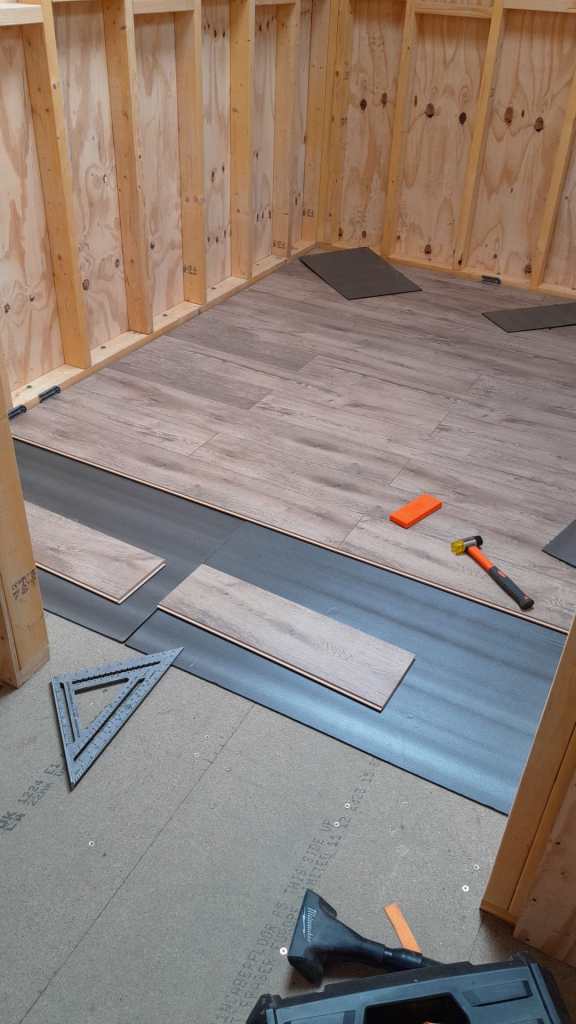
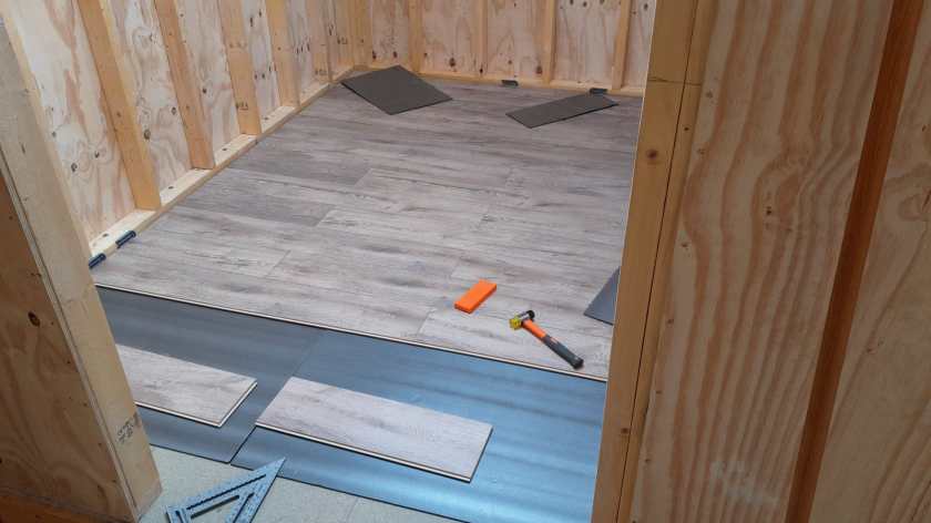
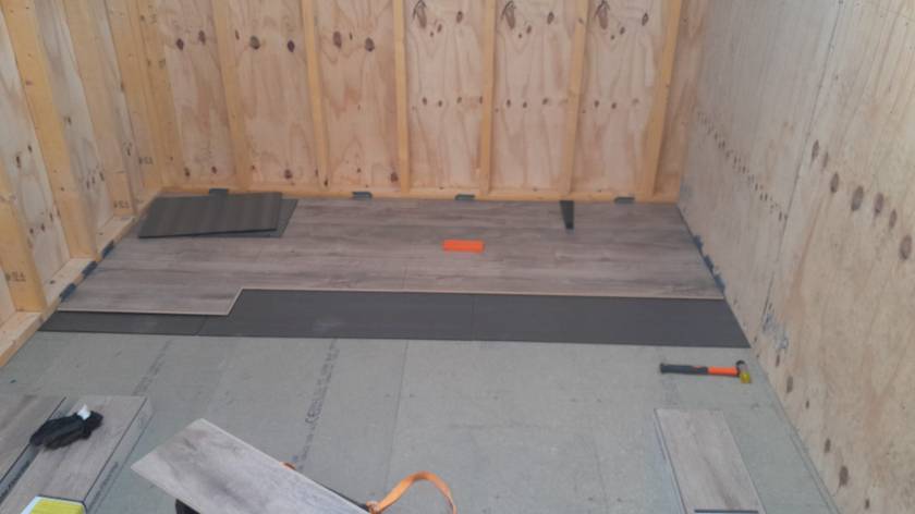
Here is a quick overview of the current state of our laminate flooring: By now, we completed the kitchen, the bathroom, the bed room and the study.
Still to do: utility room, storage room, living room and two hallways. So, not quite there yet.
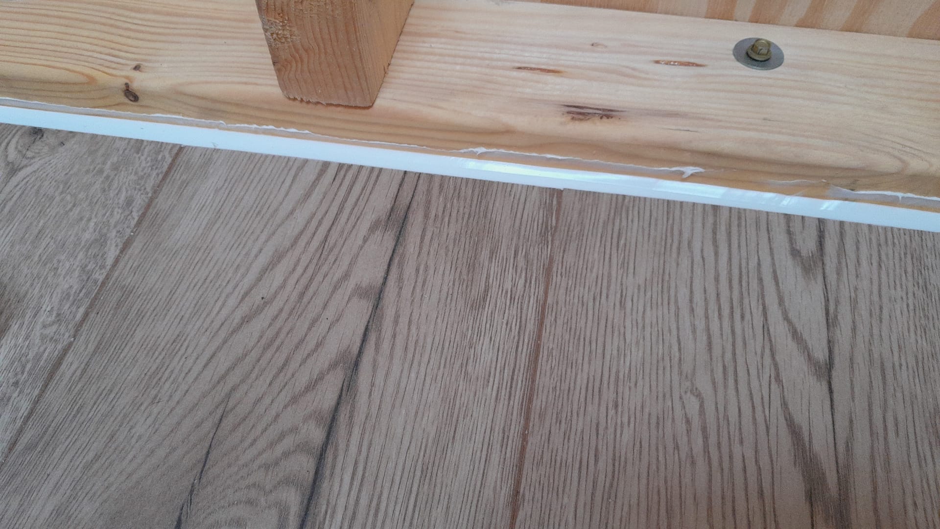
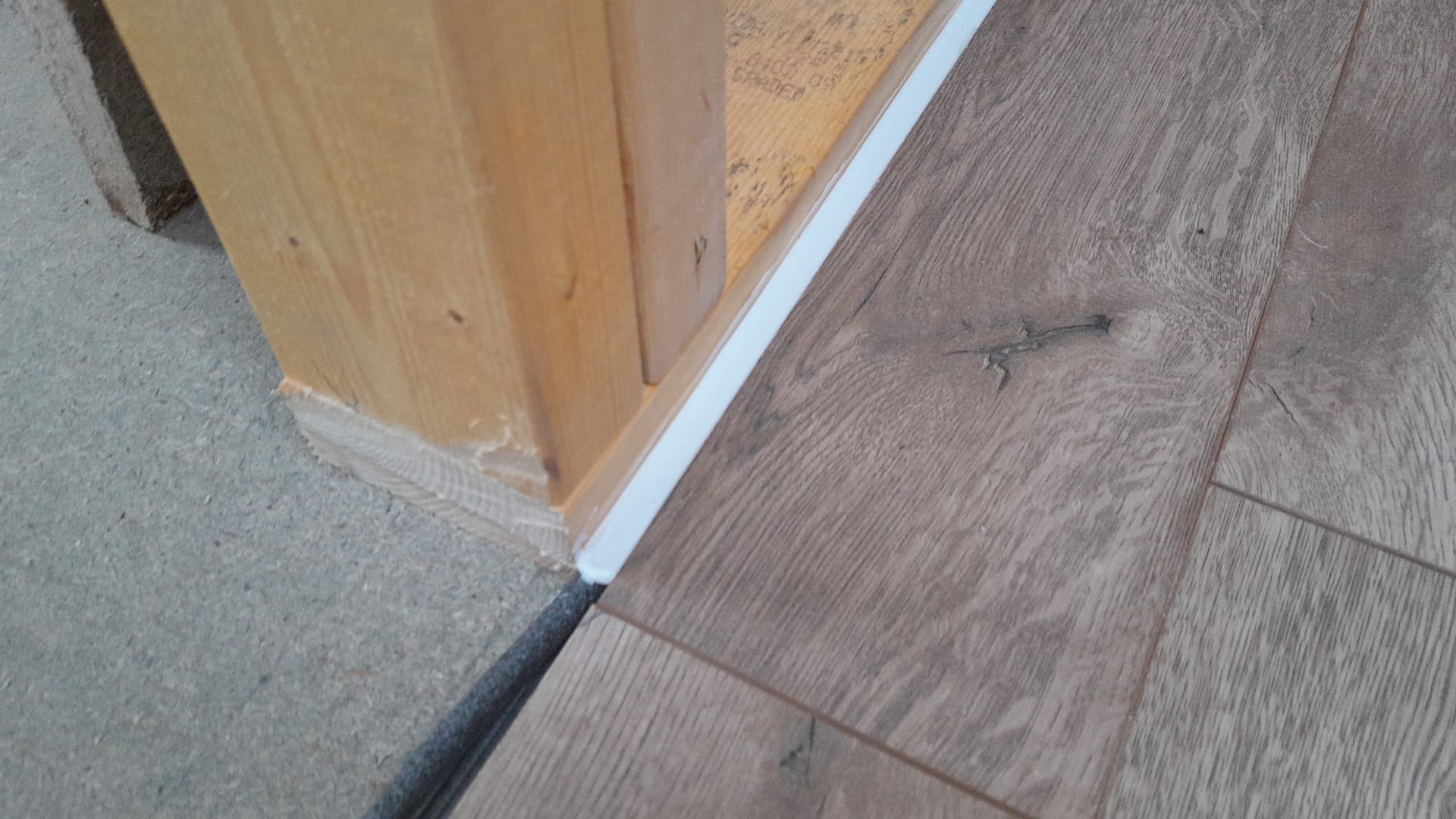
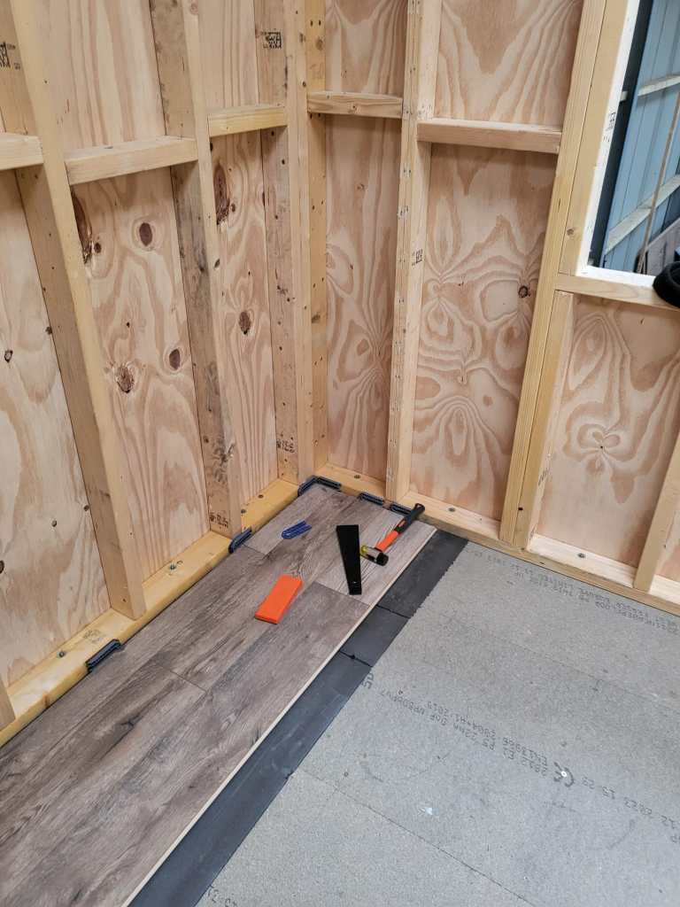
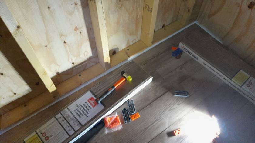
Our initial silicone tests showed we would use way too much silicone (around 6* 310ml per small room) to fill the required 12mm gap between the laminate and the wall. So, we went for a 10mm foam backing rod and put the silicone on top – with the help of a Hilti Dispenser and Fugenfux. We got the silicone from Screwfix: Sanitary Silicone White 310ml 12 Pack. And the result looks like this:
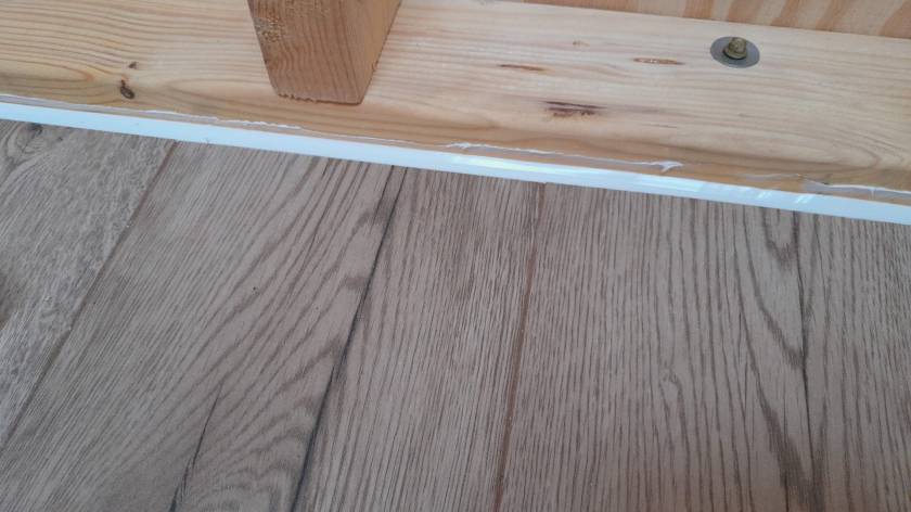
Still improving the corners …Laminate with silicone without skirtingSilicone with backing rod
Out of the box the MultiPlus comes preconfigured with a pair of 1m35mm2 (2AWG) welding cables (and as a side note: with unusually thin M8 cable lugs).
When connected to a 12V battery based on 4s Eve LF280K cells, the maximum current drawn can go beyond the recommended 0.5C rating – especially when the cell voltage decrease under the nominal 3.2V or the total cable length is longer than 1m. Using a larger inverter or smaller cells will make things even worse.
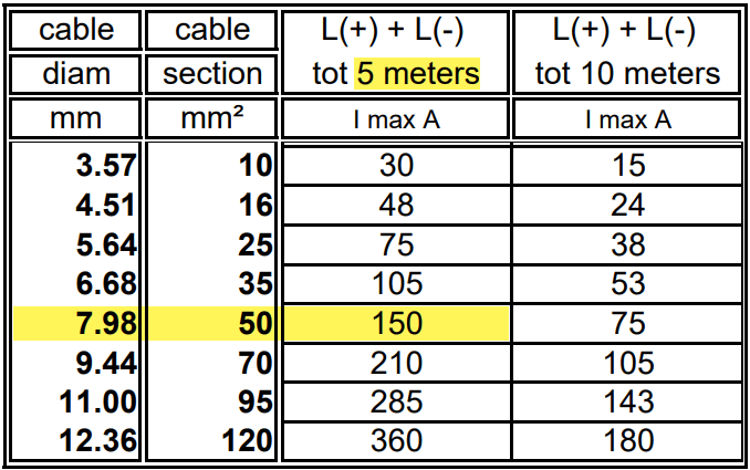
And when we look at Victron’s Recommended battery cables document, we see that they are recommending 50mm2 for currents up to 150A anyway (for cable lengths of up to 5m).
For a 1m cable the theoretical voltage drop is within their recommended range of 0.259V. But they explicity state that resistance leading to additional voltage drop due to contacts is not calculated into the recommended cables size.
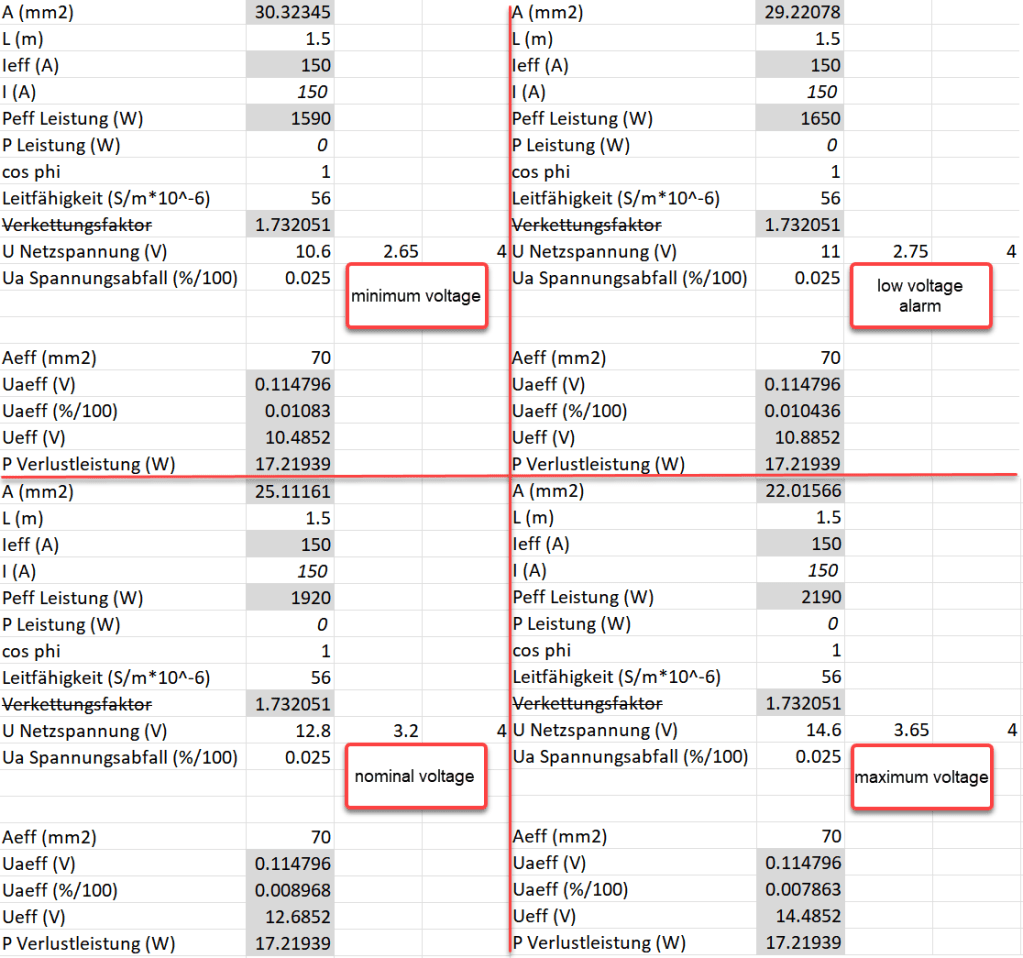
Already a cable size of 2m will lead to over 3% and 0.3V voltage drop when the cell voltage is only 4* 2.6V = 10.4V (and by default raise a “Low Voltage Alarm” on the MultiPlus). And even a cell voltage of 4* 2.75V = 11V is close to 3% and over the recommended threshold (of course, calculation is based on full inverter load of 1600VA). Besides Victron explicitly recommends a voltage drop of under 2.5% in their Wiring Unlimited document.
So why is Victron fitting the inverters with only 35mm2 cables? Especially since they are using welding cables that are only rated up to 60°C. I do not know.
But I do know, how I can fit an additional 35mm2 pair into the inverter and minimise a potential heating problem.
Adding a second pair makes particular sense at least in my case, as I am using a JK-BMS and Eve cells that both come with two M6 terminals per connection point. So running two cable pairs to battery and BMS saves me from using a bulkier and stiffer 70mm2 cable that I would have to split at the BMS and main positive cell anyway. And with that, I can still use the Anderson SB175 connectors with regular housing and 1383 wire contacts and without having to resort to 2/0 housings and 1328G1 wire contacts.
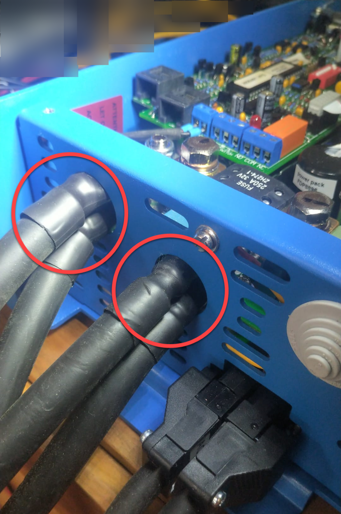
The inverter comes with 30mm holes in the front panel where the supplied cable is fitted with an M25x15mm cable gland (side note: why are they using IP68 glands when the whole inverter is only rated at IP21). Eland H07RN-F 35mm2 cable has a diameter of 14.6mm, so actually two of these cables do not fit through the holes at once.
But as the cable lugs are actually that long that they stick out of the chassis the required diameter is 2* 12.5mm = 25mm which is just the size of the hole. When wrapped in heat shrink we need some more space. And certainly we want a little bit of head room, so the cables do not scratch against the metal when moving.
So, the M25 holes had to be enlarged slightly to make space for the double cable lugs as seen on the picture below. I used a Hilti GDG 6-A22 grinder for this. I covered the inverter to prevent metal splices and dust getting inside (board, circuity) of it. And I added extra insulation around the cable lugs to prevent them cutting into the metal.
Bottom side of MultiPlus with enlarged holes and extra cable insulation
Mounting the cables to the connection points is done with two Klauke M8 35mm2 DIN 46235 compression cable lugs (back to back).
Note: the compression cable lugs from Weidmüller will not fit, as their connection plate is too long.
Instead of the factory supplied washers, spring locks and nuts, I use M8 serrated washers and lock nuts. As the negative connection point (which is directly under the 250A MEGA fuse) is around 2mm higher than with only one cable lug, I added an additional (copper) washer under the fuse terminal to make more space.
I could cover the original bolts with insulation tape to prevent accidental contact with the chassis when squeezed (but this is something that could have happened even before).
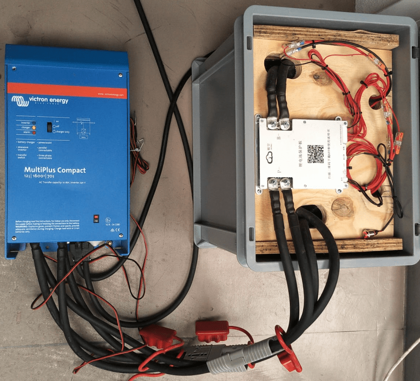
Victron MultiPlus Compact 12/1600/70-16 with dual 35mm2 battery cables
Now we have a 2* 35mm2 = 70mm2 connection to our battery as seen below.
2* 35mm2 connection between battery and inverter
So the voltage drop over the whole cable (1.5m from invert to battery with 70mm2) should be around 114mV:
Voltage drop at different cell voltages
So as it seems, the main difference between the larger and the smaller cable is the power loss (17.22W vs 34.44W at full power or 15W vs 30W at 0.5C). So all in all we save nearly 0.84% battery capacity per cycle with the thicker cables (which is 5000Wh over the whole cell life) – probably less than we spend on the cables and lugs, the labour and the time to do the calculation and writing up the article …
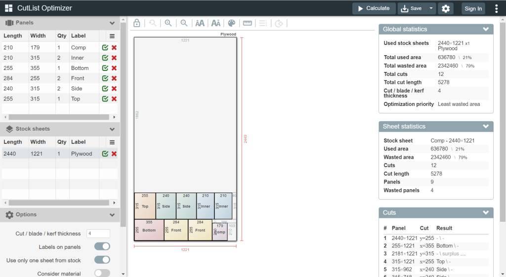
For this build, I planed all the boards after cutting, before putting in the cells. With this, I hoped to minimise the chance of any particles on the board damaging the cell insulation.
And for the small board at the short side of the case, I did also use 20mm plywood, but planed it several times until it I could just slide it in.
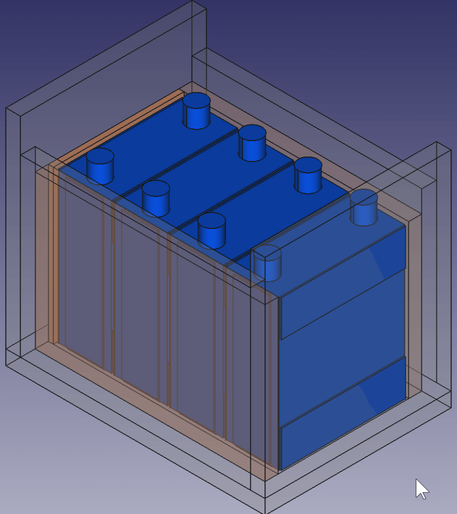
This is how the wooden case looks with the cells and insulation boards (shown in red):
Top view: battery cells with depicted insulation boards (shown in red)
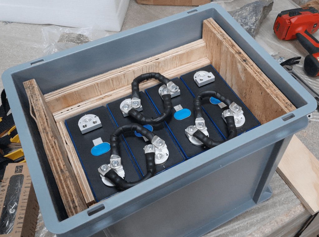
Note: when using a JK-BMS I found it important to have the main negative connection point on the upper left (or lower right). Only with this orientation it was (relatively) easy to connect the cell to the BMS.
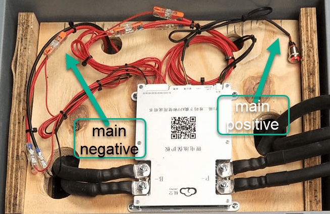
BMS connected to cells
It needed some fiddling to get the main negative cable pair to the BMS and the main positive cable pair out of the frame, as we can see from the image above.
The connection to the individual cells are fed through WAGO 221-2411 2 conductor inline splicing connectors. The holes into the top board were done with a forstner bit and a jigsaw. This version of the BMS can be fixed with four screws to the board (so no need for wire straps as with the 24s version).
Again, instead of a display I just used the pluggable power button that is connected to the display port of the BMS to power on and off the device.
In the end, I added Anderson SB175 connectors and 1383 (2AWG) contacts to both pairs and connected them to the inverter.
cell contacts were secured with M6 serrated washers and M6 16mm steel bolts;
BMS threads B- and P- were secured with M6 lock nuts to M6 16mm steel bolts (with the bolt upside down);
cell wires from the BMS were fitted with uninsulated ferrules;
cell wires on the positive cell poles were fitted with ring lugs and a 2.5mm2 hookup wire;
I added handles to the SB175 connectors to facilitate disconnecting the cable pairs;
I added dust covers to the SB175 connectors;
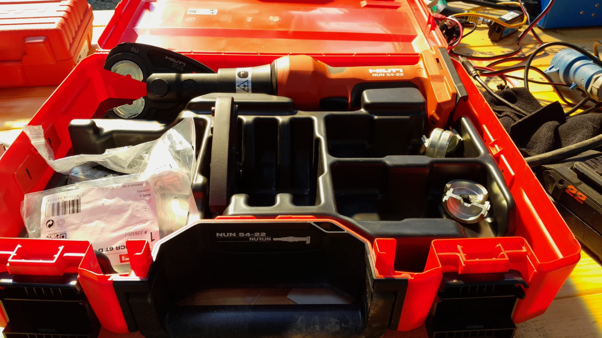
all compression cable lugs and the SB175 were crimped with a Hilti NUN54-22;
all cable lug connections and Sb175 were heat shrinked;
I added 2*35mm2 cable pairs with SB175 connectors to the inverter by replacing the existing 35mm2 welding cable with M8 lugs (you still need M8 lugs on the inverter positive and negative terminals).
Things to improve next time
Mount the SB175 connectors to the outside of the container With this the lid can be closed and the cables and BMS are better protected against pulling;
add 3A inline fuses to the cell wires;
use 45° angled cable lugs for main positive and main negative to make it easier to get the wires routed outside the container;
feed an additional wire pair for the voltage sensor from the main positive outside the container to be able to connect it to the inverter (but I am not too sure about this, as I think the voltage drop on the 2*35mm2 connection is neglectable – it might better to add a temperatur sensor to the main positive):
add a Victron MK-3 USB-C interface with RJ-45 cable into the case (to be able to restrict AC power on the inverter).
What did it cost?
Cost calculation for the 4s battery including case and inverter
Summary
This case is not as complete as the 8s version – due to its form factor. Neither the inverter has an RCBO nor the battery has a DC MCB. This has to be added separately (incurring additional cost and space). As written above, the 4s version is more like a traditional battery. However, the form factor is quite compelling; 3.5kWh in 400mm x 300mm x 325mm case. Especially in combination with the compact edition of the Victron MultiPlus. And the cost (as always without labour) is very reasonable, as well.
The inverter delivers 1200W constant power – in my opinion, enough for a small and mobile electricity build. Runnig a Krups Inissia Nespresso machine is not a problem, and boiling water with our 1000W immersion heater neither. Worst case, you could also run a 300W infrared panel heater for more than 11 hours.
One drawback of the inverter is probably the relatively small charger. With 70A at 12V it can only charge the battery with around 840W. This is certainly not the problem of the battery which would support charging up to 1344W.
A couple of months ago, I purchased a Hilti NUN54-22, a cordless crimper and cutter. Originally, I wanted to go for a device from Klauke as I am using Klauke compression cable lugs for most of the time anyway. But they only offered their tool with either Bosch or Makita batteries. And I did not want to start to invest into a new battery platform.
So, for me it was going to be only a tool from either Hilti or Milwaukee (the only manufacturers for battery powered tools I have). When I looked closer at the Hilti device, I found striking similarity to one of the Klauke devices offered. And the accessories like crimping dies seemed to be pretty much -well- identical, as well.
So, I asked my local Hilti sales manager what this was all about. Officially, no answer. But inofficially, the Hilti tool seemed to be a Klauke clone.
Soon after the purchase, after I realised that Hilti themselves only offered crimping dies for compression cable lugs, this came in really handy when I needed a crimping die for pre-rounding wire: the RU2210.
Recently, when I converted most of my electrical sockets and connectors to Neutrik powerCON True1 TOP, I was looking for a Neutrik power distribution. After some failed tests to build a box myself from an junction box, I found a product called Mini Brick from an italian company called Valentini which was sold via Distribution Zone in the UK for a retail price of 145 GBP (174 GBP incl VAT).
The box is essentially a 6-way (and not 7-way as shown above) power distribution rated up to 3500W (nearly 16A @ 230V) and has a red status light to indicate if it has power.
Build quality is very good (metal or hard plastic case, rubber coated); and the price is also understandable, as the chassis connectors alone would cost around 60 GBP. However, I was not totally happy with it due to is relatively massive form factor: L80mm x W75mm x H300 mm plus connectors.
To cut the holes for the chassis connectors into the case, I used a Hilti 30mm hole saw with my Wabeco drill stand. Drilling the duplex chassis connector obviously needed 2 holes and a cutting away some excess plastic (later on I found out that a 25mm diameter is better suited for the smaller part of the duplex connector):
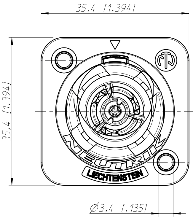
Opening for the Neutrik NAC3PX-TOP duplex chassis connector
Note: one might be even able to use 29mm and 24mm holes, see the detailed drawing – maybe I try this next time.
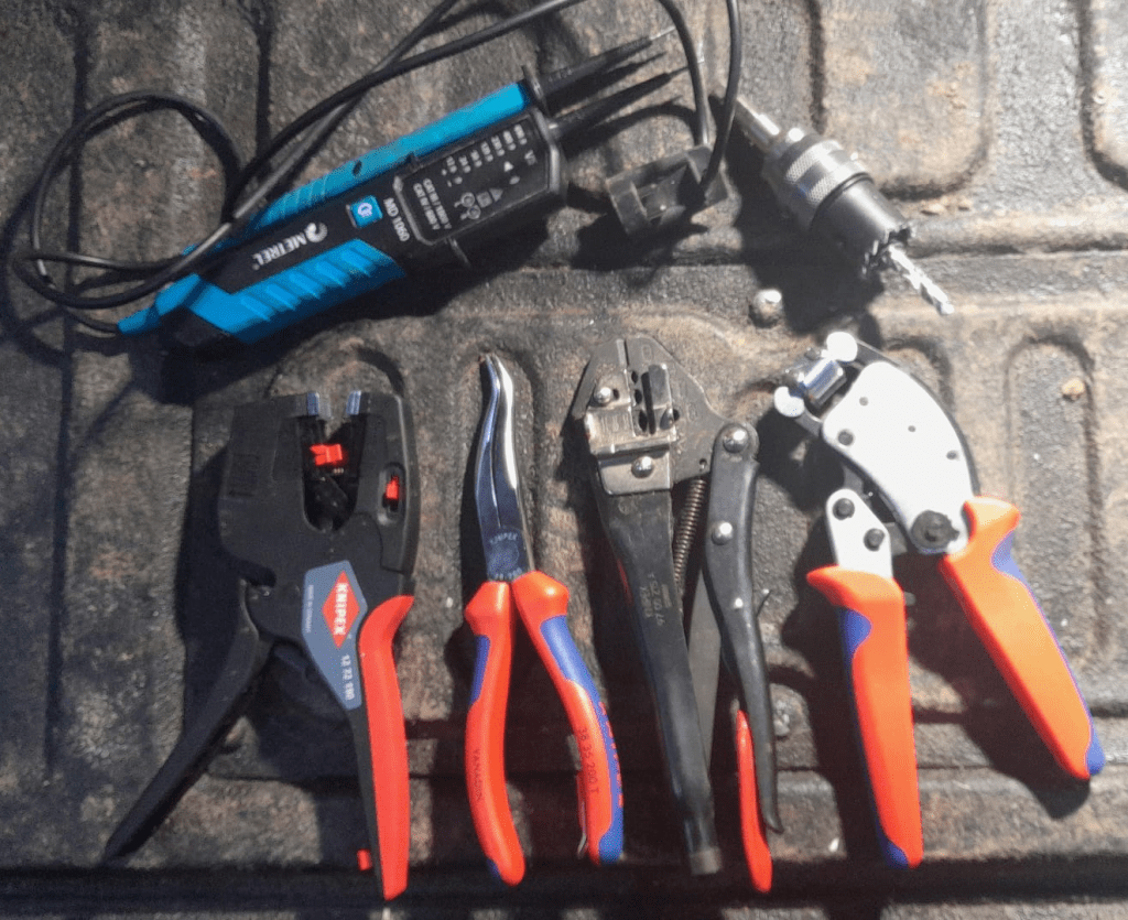
To mount the chassis connectors onto the box, I used M3 screws and hex nuts (I could not find TX versions) which I drill with a 3mm Hilti HSS-Cobalt drill (yes, overkill – but the only drill I had at hand). Unfortunately, the screws were a slightly too short, so it was a little bit of fiddling to get the hex nuts onto to the screws.
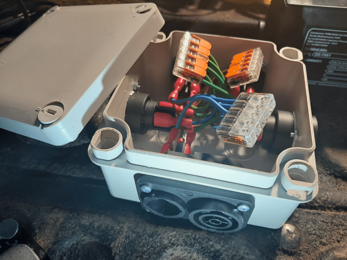
After all the Neutrik connectors were installed, I wired them to a 5-way Wago 221 COMPACT series splicing connector (221-415) with fully insulated blade receptable connectors (1.5mm2, 0.8mm, 6.35mm) to the socket and with 1.5mm2 ferrules to the clamp.
After assembly I did a final connectivity test to ensure all wires (L, N, PE) were correctly connected. As the duplex connector has a different wiring layout, it is easy to mix things up (PE is in the middle and not at the side).
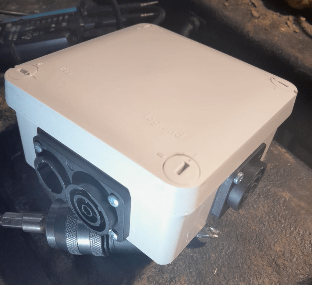
5-way Neutrik powerCON True1 TOP distribution in a LeGrand Plexo junction box
The end result is not as sturdy as the Mini Brick, but much lighter and smaller. And if I ignore the amount of labour I put into the build, this box is certainly much cheaper.
Video: 5-way Neutrik powerCON True1 TOP distribution box made from LeGrand Plexo
And as usual: electrical installations can be dangerous – only have them performed by qualified personnel.
Today I started cutting away some gorse to improve the track towards the entrance of the Rabbit Run. Under the gorse a lot of rocks came visible which might become a good foundation for a real path.