I recently wrote about our upcoming solar PV adventure. But before updating our system, I thought it was time to document and explain our current setup (with the help of KiCad).
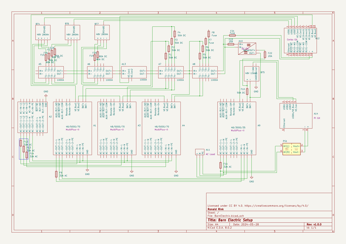
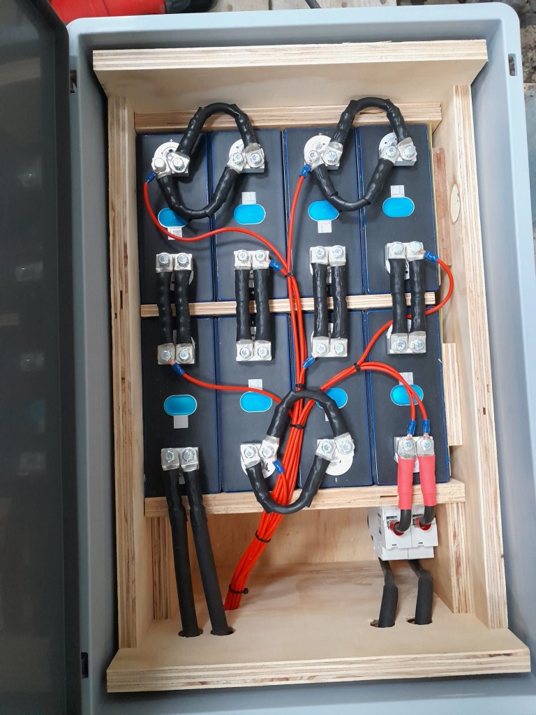
This system is the main electricity for our barn and currently consists of three batteries with an energy (often referred to as “capacity”) of 3* 14.33kWh = 43kWh (battery bank A, A1:A2 on the plan). These batteries are charged by a JCB G20QS (B1) via three MultiPlus-II 48/5000/70 inverters/chargers (B1:C2) which are by default in “Charge Only” mode. The MultiPlus-II are configured in a 3-phase configuration but only turned on when 3-phase is actually needed.
The main power is delivered by a MultiPlus-II 48/3000/35 (B4:C5) that is connected to a separate battery bank (battery bank B, BYD LVS Premium Battery-Box with an energy of 8kWh). This latter MultiPlus-II is connected to L1 of the 3-phase MultiPlus-II. So, whenever the main batteries get charged the cascaded inverter will also be charged. In addition, we can then use PowerAssist to up to supply 8'000VA (= 5'000VA + 3'000VA) when running on batteries and up to 14'500VA (= 6'500VA + 5'000VA + 3000VA) on a single phase.
Though the generator can supply up 14'400W the chargers of the Multiplus-II can only charge with a power of up to 3* 48V* 70A = 10'080W. This is actually an advantage as the optimal efficiency factor of the generator is roughly at 12'000W. So with 210A we are pretty close. If we ever added more chargers to the system we could even slightly increase the charge current to 250A.
System A with the 3-phase inverter configuration is connected to a Lynx bus bar (A1:B4) that also includes a Lynx shunt (B3) used for measuring over all batteries. In addition, there is an islolated Orion-Tr DC-DC charger (A5) that constantly feeds system B.
System A and B are connected to their separate GX:
system A Cerbo GX, A5:A6 MultiPlus-II via VE.Bus, Lynx Shunt via VE.Can, JK-BMS via RS485/USB
system B Raspberry Pi4running VenusOS, B5:B6 MultiPlus-II via VE.Bus, BYD BMS via VE.Can (on a Pi GPIO Hat)
And this is it for the electricity installation in our barn.
Note: This cascaded setup is officially not supported by Victron, but it has been working for us without problems for months now. This might be different in your case.
The other day, I realised that I never wrote about the case build of our 16s 48V batteries, as I did for the 8s case and the 4s case. So, here it is – and I am actually describing 2 revisions as we made some adjustments.
First, the total weight of the cells alone would be roughly 16 * 5.3kg ~ 85kg. This is way beyond what a single person can – or at least should – lift. So, I deciced to split the battery into 2 separate cell blocks of 8 cells each (similar as I did split the 8s battery in the Toyota HiAce). With this approach, I would be able to:
reuse the 8s design (including the RAKO boxes)
be able to move or lift half a battery (which weighs roughly 53kg)
This battery has a nominal capacity of 3.2V * 16 * 280Ah = 14'336Wh and can be charged or discharge with up to 140A ^= 7'168W. We currently have 2 of these batteries running on our 3-phase setup with 3 * Victron MultiPlus-II 48/5000/70-50.
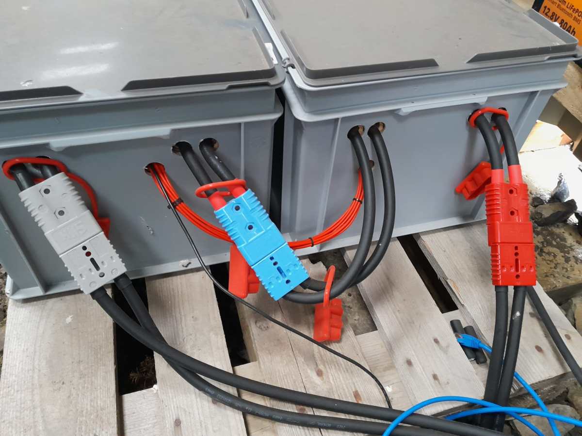
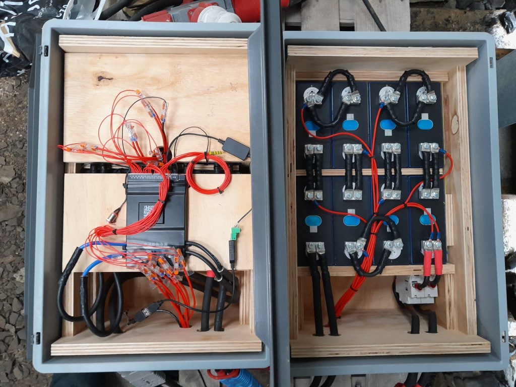
So essentially, I built 2 8s batteries with a connection cable between cells 8 and 9. The main negative and the BMS would be in one box and the main positive with the DC breakers would be in the other box. To avoid confusion, in this setup I went for coloured Anderson SB175 housings, with
Red 2 * 35mm2 H07RN-F cable main positive
Grey 2 * 35mm2 H07RN-F cable main negative
Blue Interconnecting both blocks 2 * 35mm2 H07RN-F cable connecting from cell 9 positive to cell 8 negative
In all cases
16s Battery Connectors
To connect the cells to the BMS balancer cables I extended the balancer cables with 2.5mm2 wire via WAGO 221-2411 inline splicing connectors. I then measured the increased resistance of the additional cable length and adjusted the values in the BMS configuration for cells 1 to 9.
With these inline connectors I am now able to disconnect the blocks from each other so I can move them around independently, if needed.
On the BMS, I connected a USB RS-485 TTL adapater with a USB extension cable which leads to one of the USB ports of the Victron Cerbo GX. With the help of dbus-serialbattery and BatteryAggregator I can control the DVCC settings in Venus OS.
The rest of the build is, as I already mentioned, pretty much like the 8s build.
Revision 1
Here are some images of the completed build of revision 1.
16s Battery top view16s Battery Block 1 main negative with BMS16s Battery Block 2 main positive with DC breaker
Revision 2
These are the changes I am currently making for the next revision:
add additional connectors for the balancer cables to further facilitate the disconnection of both blocks;
use 16mm2 M6 Klauke DIN46235 compression cable lugs for the connection of the main negative (cell 16) to the B- of the BMS (only relevant to the older JK-BMS), to be able to disconnect and potentionally replace the BMS;
use a WAGO 35mm2 DIN rail connector in the main negative block on cell 1/9 for the outgoing cable;
use cable glands on the external connections; (this allows for easy disconnection and re-building the block as an 8s battery);
use ratchet straps for compressing and mounting the cells to enable easier maintainability of the cells;
use Anderson PowerPole PP180 connectors instead of SB175, so I can use mounting plates for the PP180 and do not have dangling cables on the outside of the case (these connectors are expensive and increase the price of the overall build by roughly 60GBP).
However, in this case we wanted a kind of “special” setup which included the use of MultiPlus Assistants. So, in this article I will quickly describe what we wanted to achieve and how we implemented it.
In general, when connected to shore power we want to be able to limit the AC current drawn from the shore power. This is easily accomplished by setting a limit on the MultiPlus itself – or, as in our case, via the VE.BusSmart Dongle. Though the Phoenix does have a VE.Direct interface and is able to be connected to a GX device, in our setup we did not want to use a GX device. So, essentially the Phoenix can only be controlled via Bluetooth and the VictronConnect app. But configuring the AC input limit on two devices (Phoenix and MultiPlus) is not only a nuisance from a usability standpoint, but also error-prone as one (or at least we) tend to forget things quickly. So, a different and better solution was needed.
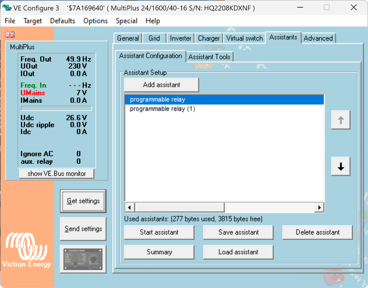
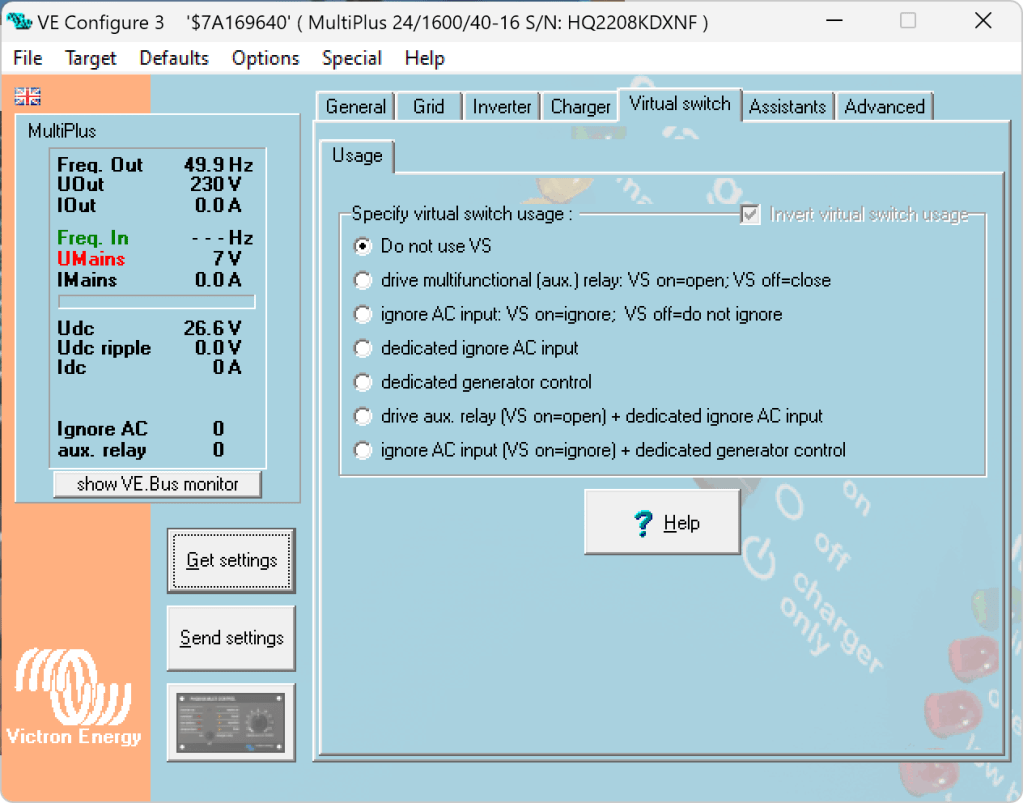
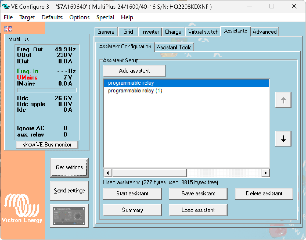
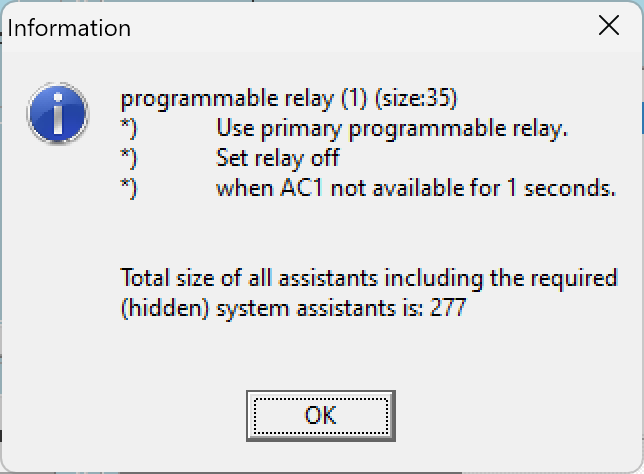
Enter the MultiPlus Assistant in form of the Programmable Relay. With this, we can configure the built-in relay of the MultiPlus to open and close based on the availability of an AC input.
Note: we have to disable “Virtual Switch” in the MultiPlus to be able to use the MultiPlus Assistant.
The Phoenix has a Remote Input connector, that can be used to stop charging when the connection is “off”. So in our case, we enabled two Programmable Relay assistants:
Programmable Relay, NC – On/Open After 5 seconds of AC input on the MultiPlus the relay is opened.
Programmable Relay, NC – Off/Closed After 1 second of no AC input on the MultiPlus the relay is closed (which is the default state).
Below you find some screenshots with the configuration in VE Configure:
Disable Virtual Switch on MultiPlusAdd 2 Progammable Relay assistantsProgrammable Relay ON after 5 secondsProgrammable Relay OFF after 1 second
So, five seconds after the MultiPlus has power via AC input it will open the relay which in turn will enable the Phoenix to start charging.
One second after AC input is gone the MultiPlus will close the relay so the Phoenix will stop charing (if it was charging at all).
The AC input of the Phoenix is connected to the AC output of the MultiPlus. So, when there is a AC input limit configured on the MultiPlus (such as 3A @230V) the MultiPlus and the Phoenix will not be able to charge with more than 3A. And from the MultiPlus perspective, the Phoenix is just an arbitrary consumer.
This can lead to some undesired behaviour if we were to limit the AC input to e.g. 1A. In this case, the MultiPlus would – when in Inverter mode – draw from the battery so the Phoenix could charge the battery. perpetuum mobile … ? And when the AC input is gone, this means that for roughly one second the Phoenix will also charge form the battery. But this is something I can live with easily.
And if we really had a very low power AC input (of e.g. 1A) we can still unplug the remote input and force the Phoenix not to charge. Or manually switch the MultiPlus to Charger mode only.
For us this is a usable solution without the need for multiple configuration changes nor the presence of a GX device.
Along with some others I am waiting for Raspberry PIs to become available again (while *not* supporting these overpriced resellers on eBay, Amazon and elsewhere).
Luckily, back in 2016 (or was it 2015?) I bought two Raspberry PI2 Model B Rev. 1.1 with 1 GB RAM and an Edimax EW-7811Un WLAN adapter. At that time the PI did not have built-in WLAN and it was said that the original Wifi dongle Raspberry Pi WLU6331 did not work with all distributions.
We had some plans what to do with the Pi – but they never made it into reality. Instead, they went into the locker.
Edimax EW-7811Un WLAN adapter
Fast forward into the future, the whole world experiences stock supply shortages and a Raspberry Pi (now in its 4th generation) is hard to get hold of.
As I am building a couple of batteries mostly with JK-BMS I need a RS-485 connection to my Victron inverters to control charge and discharge currents. Except for the GX versions of the MultiPlus-II and EasySolar-II that _sort of_ support RS-485 (not out-of-the-box, but) in a single box, I always need an additional device like a Cerbo, BBB or: a Raspberry Pi!
But as I already wrote: I did not want to support resellers with their pharmacy pricing, so I had a look at the Venus OS compatibility list and saw that – surprisingly – even a Pi 2 is supported. So, I went looking in my shelves, lockers and other places to find these rusty old Pi 2s – and after a couple of weeks I actually found them (when I was looking for something completely different). Anyway, here they are – but only with a single GB of RAM.
Nostalgic side note: yes, there were times where I would have left out the word “only” …
I was not to sure if Venus OS would run on it. And if – how quick. It was time to find out …
Installation was straight forward: following Getting Started was all it needed. I connected the Pi to my local wired network for that purpose and makes updating and installing software much easier. At the very start I also enabled superuser and SSH access.
Note: There was a minor issue or whatever one might call it. After the install of v3.00 (via the SD card) I had the device check for an update (which at that time should not have been available). But for whatever reason, I was offered to update from v3.00 to v3.00. I did that and it worked and after that no more updates were recommended.
From then on, installing additional packages worked without an issue – but took considerably longer than on a Cerbo, Pi 4 or even the GX in the EasySolar.
One thing just seemed to be missing. Having the Pi to act as a Wifi access point (and router with DNS and DHCP). Why would I want this?
Some of my batteries are just standalone installations in a car, trailer or other machinery. And external network is not always available. And I do appreciate the comfort of wirelessly connecting to the GX – just as I am used to when using my EasySolar-II GX.
And as nearly always: I was not the first one to ask for such a feature:
After a reboot, I could successfully connect to the access point and VictronConnect immediately found the “Cerbo”:
Raspberry Pi 2 Model B Rev. 1.1 as a Victron GX device while acting as an access point
After I enabled the access point (or tether option) I could no longer see or access any other SSIDs from the Pi:
WLAN client is deactivated when running an access point
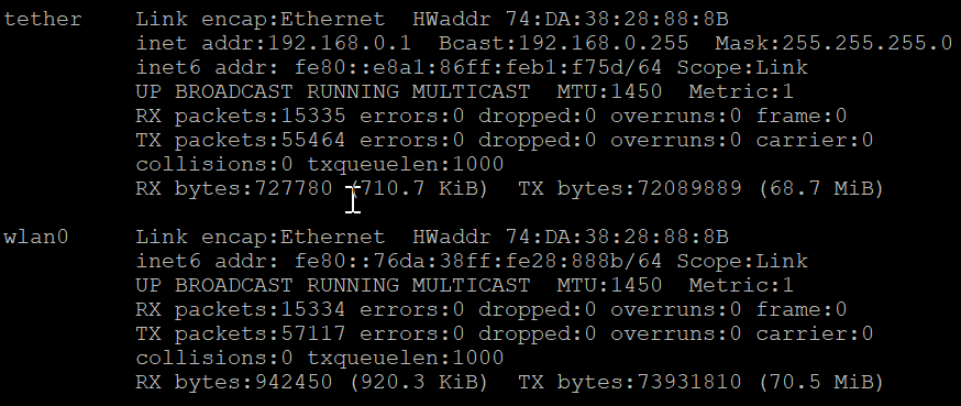
Running ifconfig gave me this output:
ifconfig output after enabling the access point
Certainly, I was interested in the performance or resource consumption of the Pi 2. As it turned out, the UI really took some CPU but the additional network services themselves were not quite as hungry: idle floats between 71% and 92%.
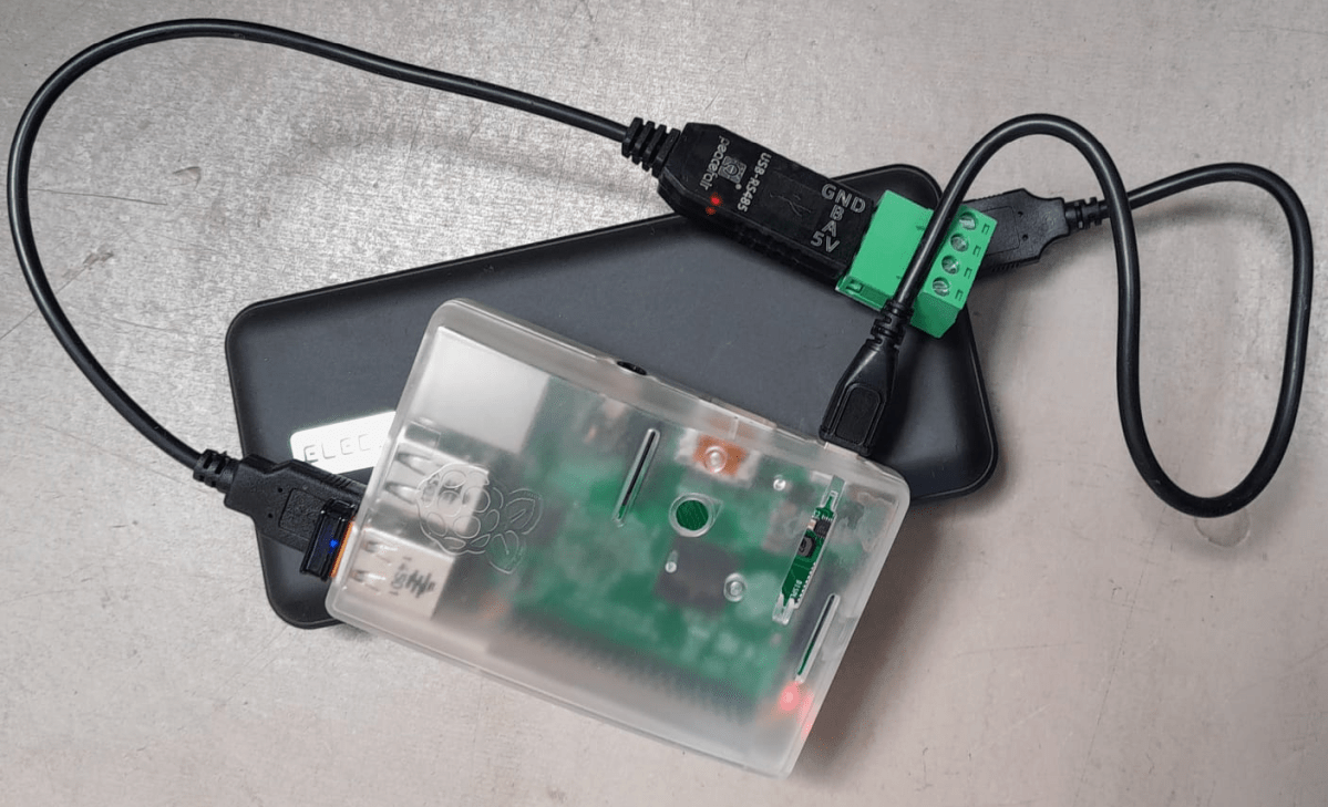
Pi 2 running with a RS-485 adapter and enabled access point
So, this is it. My investment of roughly 35$ in 2016 (even with intereste rate) really paid off. I have a working GX device that does everything I want – plus an access point – all in a single box.
Pi 2 running with dbus-serialbattery, BatteryAggregator and access point
The other day, I connected my BYD Battery-Box Premium LVS 8.0 to a Victron MultiPlus-II 48/3000/35-32. Here are the steps I took to do it and some errors I ran into.
The Battery-Box needs to communicate via CAN with the inverter. And as Victron inverters do not come with a CAN port by default (unless you go for a MultiPlus-II GX or EasySolar-II GX) we need a GX device. Originally, I wanted to use my Victron Cerbo GX for that, but since we moved into the caravan the device is gone missing. Luckily last year, I supplied myself with a couple of Raspberry Pis (at least model 3and 4 are supported) that could run a Venus OS and act as a GX device. And as I was not the first one doing that, I thought it would be just too easy – well, it was easy after I did everything right.
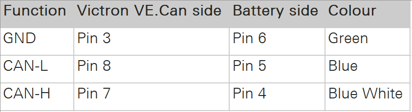
Normally, Victron requests to use a VE.Can to CAN-bus BMS Type A cable to connect to a BYD battery. This is actually an ordinary CAT 5e network cable with RJ45 connectors where only the relevant CAN pins (and GND) are connected.
In order to screw the wires to the CAN hat terminal, I used uninsulated ferrules. Otherwise the Cat 5e wires would have been too soft and light for the terminal.
Installing Venus OS on the Raspberry PI 4
For the Raspberry PI 4, I followed the documentation and installed the standard (and not the large) image. At that time, v2.93 was the newest version (see here for directory of all versions). I uncompressed it and used Win32DiskImager to write the OS to a MicroSD card (all done on a Microsoft Surface Go2 running Windows 11).
Note1: at first, I did the install with a Raspberry Pi 3 Model B V1.2 which also worked fine. However, the CAN device on the Victron UI then did not show any packets but worked without problem.
Note2: The Raspberry Pi 4 is a model B Rev. 1.5 (I mention this, as I saw comments that indicated that there might be a difference between different revision from 1.2 onwards).
Note3: I activated the “Mobile” tile to be able to change the charge current via the overview screen.
The CAN driver then had to be installed separately. As I did not have direct internet access from the Pi, I used the offline install method with a USB memory stick.
As written in the documentation, I copied the compressed installation files as venus-data.tar.gz to the root of the USB drive and restarted the Pi. To verify the automatic installation was successful check if there is a new menu item Package manager at the end of the Settings list. If not visible check if you can find SetupHelper in /data. You can always manually copy it from the SDCard (use mount to see where the card is mounted) and then run setup yourself. I did a reboot after every package.
New menu item in Settings after installation of SetupHelper
Same procedure here. Copying the compressed installation files to the SDCard as /venus-data.tar.gz. Then run the package installation manually if for whatever reason the automatic install does not succeed. See below what the package manager should look like after the installation of both packages.
List of active packages in Package manager
Installing the driver
Configuring the driver had to be done from the terminal. There was a minor issue for me which I did not get right the first time. When asked to install an interface via the i option I actually had to type in a hat. I named the device hat0 and after the reboot it showed up as hat0 (can8) can8 spi0.0. In my case it was the “Waveshare 1-channel CANbus Hat 12 MHz crystal” (check the imprint on the silver part on the hat to see the crystal speed).
Configuring CAN bus
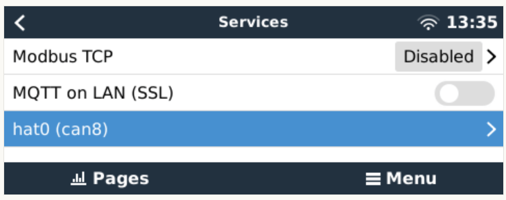
There is really not much to configure. The only option under “Services” is to set the communication speed which is 500kB/s for BYD. If the CAN adapter does not show up make sure the correct type has been selected in VeCanSetup. For me it just worked out of the box.
CAN hat showing up in ServicesSetting the CAN speed for BYD Battery-Box BMUConfigured CAN bus
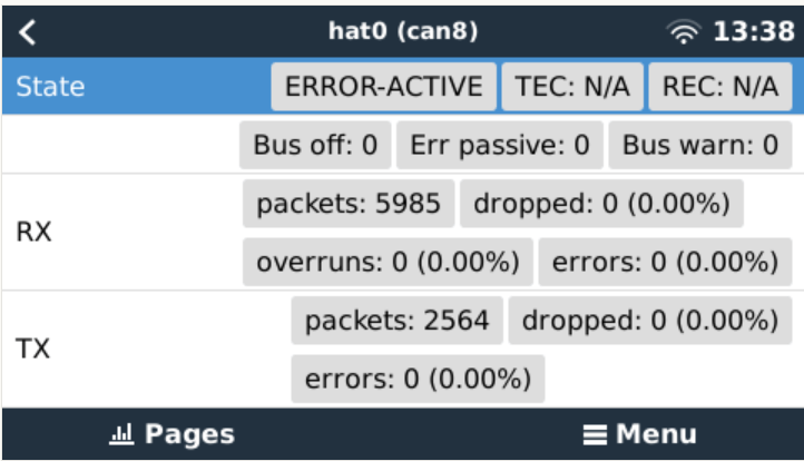
Before the BMS is connected the CAN should show up as ERROR-PASSIVE. As soon as the communcîcation worked it changed to ERROR-ACTIVE.
CAN bus ERROR-ACTIVE with actual traffic
Note: When I tried with the v2.93 on the Raspberry Pi 3 the RX/TX counters were always empty (but nevertheless worked). Via ifconfig the packets were correctly shown. But with the Pi 4 traffic was shown on the UI right from the start.
CAN bus traffic via ifconfig
I did not connect the CAN cable at that point but configured the Battery-Box and the inverter first.
Commissioning the inverter
I used a USB MK3 adapter with an RJ45 Cat 5e cable connected to the VE.Bus of the inverter to configure the MultiPlus.
I used VEConfigure 3 and VictronConnect (to be able to configure via VictronConnect I had to use the zzz password to get out of the read-only mode).
First, I updated the firmware of the MultiPlus via VictronConnect and then continued with VeConfig.
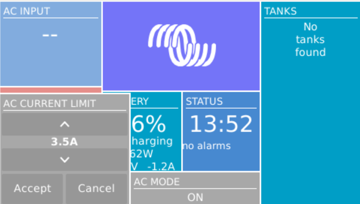
Basically, I set the inverter to off-grid and did not enter a country code. For the battery type I selected “Lithium Iron Phosphate” and accepted the default settings. I set the “AC current limit” to a maximum of 20A (the maximum my generator could handle) and activated the option to have it overruled by “Remote” (which can also be done via the GX Remote Console or VictronConnect).
Setting AC current limit via GX remote console
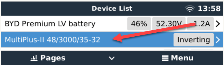
I also activated DVCC to later have the BMS tell the inverter when to charge and how to discharge. This was pretty much it. So I connected the MultiPlus via the VE.Bus and the MK3 cable to the Raspberry where it showed up instantly.
Inverter shows up after connecting VE.Bus to the Raspberry via MK3
Commissioning the Battery-Box
After assembling the battery which conisted of only stacking both battery modules on top of each other followed by the PDU on the very top I connected the BMU via the grey RJ45 to the PDU. After turning on the top most battery the BMU started as well and I was able to connecto to the WiFi of the BMU from the BeConnect app (Android or Windows both worked for me, the latter actually showed more information).
Via the app I pre-downloaded a current firmware and after switching to the BYD access point I applied the firmware (actually two different firmwares). After some waiting the new firmware had been applied and I could configure the basic settings: inverter manufacturer, number of battery modules.
At this stage I connected the 35mm2 cables from the battery to the inverter. I bought the cable preconfigured with the battery. And I used a Littelfuse JLLN-125X (class T) as a fuse between both devices.
Connecting the battery to the Venus OS
And then I connected the BMU to the GX. After some seconds, the inverter clicked and started charging. Essentially, DVCC turns on automatically (even if turned off before) as soon as the CAN communication is established.
In the GX overview the battery appeared and gave some additional information (see next section for details). All parameters between battery and inverter were exchanged automatically.
Things I noted
The battery turns itself off after a while when no communication via CAN is possible. This behaviour is described somewhere in the BYD manuals.
Charging the battery does not work when no CAN connection can be established. The inverter stays in “Absorption” mode with a current of 0A.
A more detailed description of the pin layout can be found on the BYD manuals. See images below.
The GND pin is not required for communication between the BMU and the VE.Can GX. Only BLUE for CAN-H and BLUE-WHITE for CAN-L are going into the CAN hat.
In addition to the official web site bydbatterybox.com the web site eft-systems.de provides additional information and downloadable documentation.
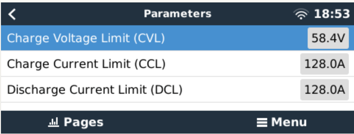
When charging the Battery-Box for the first time, I eventually reached a 100% SOC. Until that point the charge current stayed nearly constant at around 30A (Bulk). It decreased to around 1.2A and the inverter turned to “Absorption” but never stopped charging. At some point one of the cells reached a voltage of over 3.7V which resulted in a warning on the GX. Nevertheless, charging continued. I manually switched off the charger after the second time I received a warning due to high cell voltage. I would have expected to have the inverter automatically stop charging at a 100% SOC. Maybe the BMS only measures the charge voltage limit (CVL) which is defined as 58.4V and not the individual cells?
The cells in a battery were not really well balanced (delta >= 100mV). I would have expected a better balancing. Actually, I do not know if the BMS has a balancer at all. I could not find anything in the documentation.
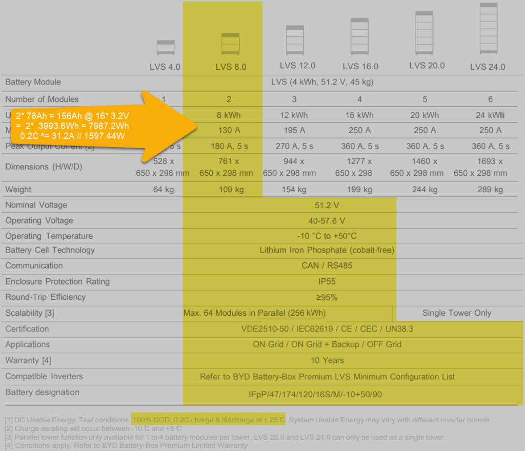
Each LVS 4.0 has a capacity of 78Ah @ 51.2V = 3993.6Wh. The GX shows this information in the “Details” item within the battery. I could not find this information in the manual.
The BYD manuals state, that the lifetime of the battery can only be achieved at 0.2C, which limits a single LVS 4.0 to 798.72W (or 1597.44W for a LVS 8.0) – this is a ridiculous small amount.
Charge current was initially restricted to 38.4A by the battery, only after a day or so, the charge (CCL) and discharge current (DCL) went up to 128A. In my case the inverter only support 35A max, so no issue with that.
Startup sequence Start top-most battery first by pressing the power button for a couple of seconds; then start the BMU if not automatically started; next start the inverter; then start the GX (in my case currently on the AC side).
Shutdown sequence Turn off the inverter; turn off the BMU; turn off the individual batteries (keep buttons pressed for a couple of seconds); GX turns off automatically.
Adding a CAN hat in VeCanSetup needs to be entered literally as a hat.
Though I set the AC charge current to 20A the inverter only drew 16A at most.
The WiFi of the BMU cannot be changed, nor the password.
BYD RS485 CAN pin layout, taken from the BYD BMU maualBYD to Victron CAN pin layout, taken from the BYD BMU manualBYD Battery-Box voltage and charge limitsSpecification of BYD LVS 8.0, taken from the BYD manuals
Future improvements
I want to connect the Raspberry to the DC side with a 48V/12V step-down converter and a 12V to USB-C adapter. Inbetween I want to add a power bank, so the GX can be configured even if all power sources are down.
Replace the CAN hat with a USB CAN adapter
Strengthen the connection of the CAN wire to the CAN adapter
All in all, the installation was straightforward. A couple of uncertainties are probably normal when doing this the first time. I would have expected more documentation (articles, videos) for this to be around. But I could not find anything for a BYD, Victron, VenusOS via Raspberry setup. Maybe others are only using a Cerbo GX?
The batteries are well built (all IP55) but extremely bulky and pricey. With around 400 CHF per KW this is more than 300% of regular LiFePO4 cells. But nevermind, lead and delivery times are in the magnitude of months.
I would have liked the BMU to be integratable into one of the PDU boxes. Now it is just hanging around separately.
Would I buy another Battery-Box? Probably not – too pricey. But good for starters. Plug and play when used with Victron and a Cerbo GX.
The Caravan we got last year did not come with an inverter, so getting coffee in the morning or running a microwave was only possible when our main generator was running. And the installed battery for 12V support had a rather small capacity. This was clear to us from the beginning, as we eventually wanted to connect the Caravan to our EVE 280Ah cells.
But since we got our Starlink internet and our router did not seem to run easily on DC power, we needed -in addition to the temporary morning AC coffee spike – a more permanent AC solution.
Of course, first I updated the firmware of the inverter and configured it work with the battery:
Setting the AC input to 16A
Setting the battery type to LiFePO4
Setting the charge current to 70A (which is over the recommend amount of 50A, but see below for details)
As I did not want to connect a Cerbo GX to the system, I just used the VictronConnect App. Maybe I add a VE.Bus Smart dongle later on, or I connect some GX nevertheless. Who knows … Until now, it needs a wired connection to the inverter to see its status.
After powering on the generator, I confirmed everything was roughly working as expected. During the first run, the SOC was shown as 100% though the BMS of the battery internal saw it differently. In addition, the reported Amps and temperature were seen differently, as well. So, even that I set the inverter over the recommended maximum of 50A for the battery, the actual charge power was never much higher than the actual maximum).
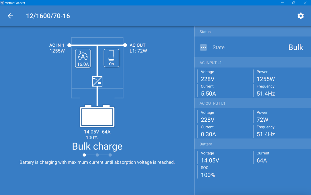
This is what the inverter saw (100% SOC, 14.05V DC cell voltage, charging at 64A):
MultiPlus charging the Liontron battery via the generator
And this is, what the Liontron BMS reported (76% SOC, 13.8V DC cell voltage, charging at 55.5A):
The SOC as seen by the Liontron battery BMS
In the end, the BMS stopped charging when it thought its batteries were full. And the inverter did not complain. However, I noticed that the cells were really not in balance (with a delta of 200mV between the lowest and highest voltage).
Discharging was ok, as well. However, I soon realised that the 100A discharge current could not be achived in my setup. The inverter tried to draw power and the BMS cut off with a “Discharge over-current” (OCD). SO, still no coffee via our Nespresso machine (and no microwave either, for that matter).
So, what is the take away of all this?
It works and now, I can run the Internet all day.
All in all, it is a relatively simple and quick setup.
The Liontron battery does somehow not live up to its specs (and yes, I know the battery could be a size bigger for what I want to achieve; but I did not want to buy an additional battery for this temporary solution).
It is way cheaper and more flexible than to buy this “off the shelf”.
Maybe, I add a Victron SmartShunt to get a more accurate SOC reporting (as I do not see any other way to integrate the BMS with the inverter).
Charging of the battery is quite fast when running the generator.