

In this article I describe what I did to install 2 pairs of 35mm2 cable to a Victron MultiPlus Compact 12/1600/70-16.
Out of the box the MultiPlus comes preconfigured with a pair of 1m 35mm2 (2AWG) welding cables (and as a side note: with unusually thin M8 cable lugs).
When connected to a 12V battery based on 4s Eve LF280K cells, the maximum current drawn can go beyond the recommended 0.5C rating – especially when the cell voltage decrease under the nominal 3.2V or the total cable length is longer than 1m. Using a larger inverter or smaller cells will make things even worse.
And when we look at Victron’s Recommended battery cables document, we see that they are recommending 50mm2 for currents up to 150A anyway (for cable lengths of up to 5m).
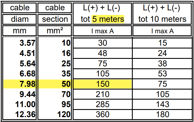
For a 1m cable the theoretical voltage drop is within their recommended range of 0.259V. But they explicity state that resistance leading to additional voltage drop due to contacts is not calculated into the recommended cables size.
Already a cable size of 2m will lead to over 3% and 0.3V voltage drop when the cell voltage is only 4* 2.6V = 10.4V (and by default raise a “Low Voltage Alarm” on the MultiPlus). And even a cell voltage of 4* 2.75V = 11V is close to 3% and over the recommended threshold (of course, calculation is based on full inverter load of 1600VA). Besides Victron explicitly recommends a voltage drop of under 2.5% in their Wiring Unlimited document.
So why is Victron fitting the inverters with only 35mm2 cables? Especially since they are using welding cables that are only rated up to 60°C. I do not know.
But I do know, how I can fit an additional 35mm2 pair into the inverter and minimise a potential heating problem.
Adding a second pair makes particular sense at least in my case, as I am using a JK-BMS and Eve cells that both come with two M6 terminals per connection point. So running two cable pairs to battery and BMS saves me from using a bulkier and stiffer 70mm2 cable that I would have to split at the BMS and main positive cell anyway. And with that, I can still use the Anderson SB175 connectors with regular housing and 1383 wire contacts and without having to resort to 2/0 housings and 1328G1 wire contacts.
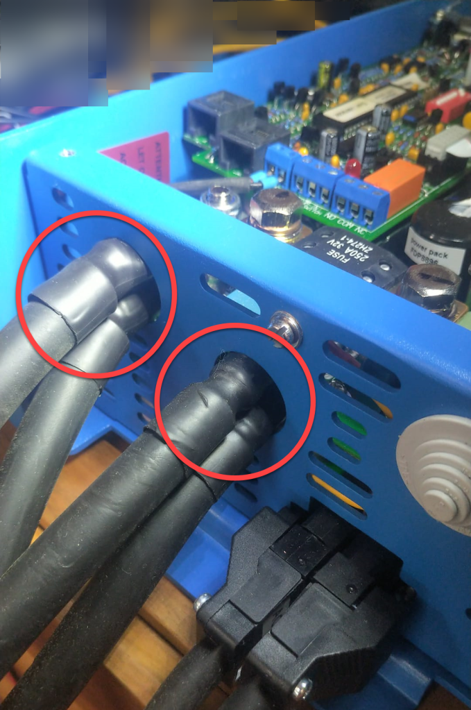
The inverter comes with 30mm holes in the front panel where the supplied cable is fitted with an M25x15mm cable gland (side note: why are they using IP68 glands when the whole inverter is only rated at IP21). Eland H07RN-F 35mm2 cable has a diameter of 14.6mm, so actually two of these cables do not fit through the holes at once.
But as the cable lugs are actually that long that they stick out of the chassis the required diameter is 2* 12.5mm = 25mm which is just the size of the hole. When wrapped in heat shrink we need some more space. And certainly we want a little bit of head room, so the cables do not scratch against the metal when moving.

So, the M25 holes had to be enlarged slightly to make space for the double cable lugs as seen on the picture below. I used a Hilti GDG 6-A22 grinder for this. I covered the inverter to prevent metal splices and dust getting inside (board, circuity) of it. And I added extra insulation around the cable lugs to prevent them cutting into the metal.
Mounting the cables to the connection points is done with two Klauke M8 35mm2 DIN 46235 compression cable lugs (back to back).
Note: the compression cable lugs from Weidmüller will not fit, as their connection plate is too long.
Instead of the factory supplied washers, spring locks and nuts, I use M8 serrated washers and lock nuts. As the negative connection point (which is directly under the 250A MEGA fuse) is around 2mm higher than with only one cable lug, I added an additional (copper) washer under the fuse terminal to make more space.
I could cover the original bolts with insulation tape to prevent accidental contact with the chassis when squeezed (but this is something that could have happened even before).

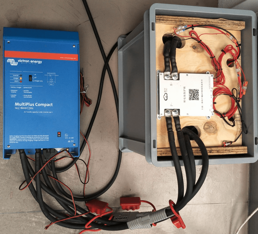
Now we have a 2* 35mm2 = 70mm2 connection to our battery as seen below.
So the voltage drop over the whole cable (1.5m from invert to battery with 70mm2) should be around 114mV:
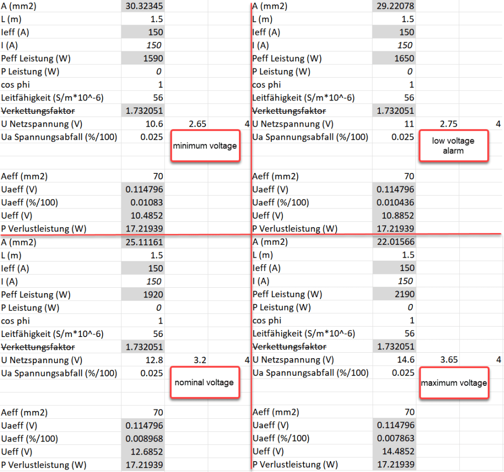
So as it seems, the main difference between the larger and the smaller cable is the power loss (17.22W vs 34.44W at full power or 15W vs 30W at 0.5C). So all in all we save nearly 0.84% battery capacity per cycle with the thicker cables (which is 5000Wh over the whole cell life) – probably less than we spend on the cables and lugs, the labour and the time to do the calculation and writing up the article …
