Crimping and using TE AMP SuperSeal 1.5 connectors

Recently, I bought some additional high beam lights from LazerLamps for our truck. For this I had to create and extend a couple of connectors. TE AMP SuperSeal 1.5 connectors, as it turned out. This article serves as an aide-mémoire to me when I have to use and order these connectors in the future. And it might be of no particular interest to you at all. So, feel free and skip reading …

First, these connectors do not have a typical male/female plug/socket arrangement. Instead, they use

  • “male” plug housing with “female” receptable contacts
  • “female” cap housing with “male” pins or contacts (called tab contacts)

The SuperSeal 1.5 connector becomes water tight (IP67) by using wire seals that have to be used on every single wire and are crimped to the contacts. So, the contacts have two crimp points:

  1. Outer crimp
    for attaching the wire seal and the insulation of the wire insulation which also serves as a bend protection
  2. Inner crimp
    for crimping the uninsulated wire to the contact – and this uninsulated part is rather short: only 4mm.
    This is suprising as the connectors are still rated for 14A.

Note: The wire seals come in different diameters and colours with “yellow” the most common size (especially when buying no-name clones).

For the correct way of crimping these connectors, I could reuse my existing Knipex Crimp System Plier (97 43 200) and just add the matching crimping dies 97 49 28 along with the wire feed stopper 97 49 28 1. The latter greatly helps to have the right insertion depth when crimping, as one cannot really see anything due to the wire seal attached to the cable.

After crimping the contacts have to be inserted into the housing. And there is only one correct and possible direction which fits. Audible and tactile feedback is given with correct insertion.

Both housings have locks (usually in red) that must be open for insertion and extraction and locked for use. Gettings these locks unlocked is quite tricky and a specialised tool is highly recommended – especially for the cap housing. The same for the actual extraction of the contacts themselves. I found it easy to destroy the contact, housing or screwdriver when not done carefully or properly.

There is a good video (in german) that shows how to use the pliers and assemble the connectors:

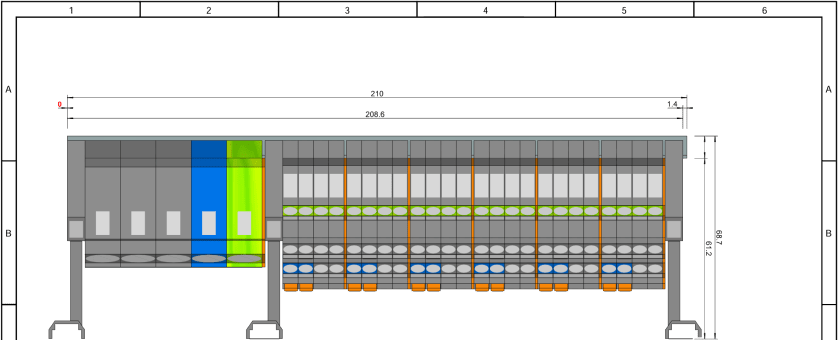
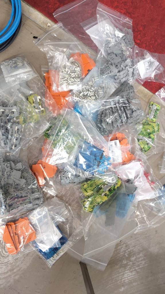
Here is a summary of most of the parts along with their contact sizes.

Cross Section mm2Plug Housing
w/ Receptable Contacts
Cap Housing
w/ Tab Contacts
Wire Seals
0.35 .. 0.50282403-1282404-1281934-4
(1.2 .. 1.6mm)
green
0.75 .. 1.50282110-1282109-1281934-2
(1.7 .. 2.4mm)
yellow
1.50 .. 2.50282466-1282465-1281934-3
(2.5 .. 3.3mm)
red
Extraction / Insertion Tools9-1579007-19-1579007-1
Positions
Number of Contacts / Pins
Extraction / Insertion Tools
1282079-2282103-12452133-1
785061-1
2282080-1282104-12452133-1
785061-1
3282087-1282105-12452133-1
785061-2
4282088-1282106-12452133-1
785061-2
5282089-1282107-12452133-1
785061-2
6282090-1282108-12452133-1
785061-2
TE AMP SuperSeal 1.5 contact part numbers (w/o gold contacts)

There are some additional parts that might be of interest as well:

Example

A complete 3-pin socket/plug for 1.5mm2 thus consists of the following part numbers:

Here is a copy of the official data sheet from TE:

Note: I first bought a cheap SuperSeal no-name clone for testing the crimping pliers before I tried with the originals. Saved me quite some money …

So, this is it for today. Hope you find this useful. It surely helped me.

Wind turbines revisited

Back in 2021, when I initially considered a wind turbine, and actually purchased a FuturEnergy AirForce-1 (which has now been acquired by Britwind), I had to find out that financially it really did not pay off to have a micro turbine. Plus, the turbine did not fully convince me, if it could really handle the high wind speeds here in Caithness.

Here is a rough estimate of the energy production and consumption per 24h of the FuturEnergy AirForce-1 for our location at 10m tower height:

FuturEnergy (now: Britwind) AirForce-1 energy generation (avg 7.1m/s at 10m)

As we can see, the turbine does not even come close to what we need. In addition, it cuts off at roughly 11m/s and has a survival speed of 52m/s. So, especially in the winter months when energy is needed most, chances are high that the turbine cuts out and -worst case- breaks if we do not lower it beforehand. This is an additional a nuisance, as lowering the tower is quite an undertaking (taking away all guy lines).

So it is clear, we need something bigger – since “more is more” (the Muldoon principle).

After looking around what works in the Highlands and Islands and what actually got a positive planning decision, I came across two options in the 5kW range:

  • Britwind H5
    aka ISKRA Evance R9000
  • Ryse Energy E5-HAWT

What both turbines have in common:

  • delivery of around 5kW peak power (at 11m/s)
  • cut-off and survival speed 60m/s+ (218km/h or 134mph)

Though the E5 seems to produce energy at lower wind speeds, it seems the H5 is more efficient at higher wind speeds. Here is some data I got from their spec sheets:

Average wind speedBritwind H5 Ryse Energy E5
20290
301900
449633900
591676900
61365310000
71787714300
82158117700
92158120000
102158122500
m/skWh p.a.kWh p.a.

The NOABL wind speed database classifies our location as 7.1m/s (yearly average at 10m) and their report shows the follwoing information at 10m, 12m and 15m height over the year:

MonthHeight 10mHeight 12mHeight 15m
January9.09.29.4
February8.68.88.9
March8.48.58.7
April6.66.86.9
May5.85.96.0
June5..05.15.2
July5.55.55.7
August5.65.75.8
September6.977.1
October7.57.77.8
November7.57.87.8
December8.68.89.0
avg m/savg m/savg m/s

Compared to each other this does not look too dramatically different. But the power being generated increases in a cubic order with doubling wind speeds.

Average wind speeds at different heights over the year

So, when I correlate this information with different turbines to our location for a 15m tower height I get the following data:

Power generation of turbines at different heights

But it becomes more interesting when we compare generated versus required power per day over each month.

Here we see that during the winter months generated power seems to be the same (or capped) at just below 60kWh per day. And it also seems that we have a surplus every month (the orange bar is the power required per day).

Power required vs power generated [kWh per 24h]

And if we now show the surplus/deficit power vs power generated we see that the E5 cannot always produce the required amount:

Ryse Energy E5-HAWT at 15m [kWh per 24h]
Britwind H5 at 15m [kWh per 24h]

From this we can see the following problems:

  • The E5 will not be able to deliver the amount of energy on its own for over 4 months and barely only during half of the year. During summer we can compensate that easily with PV if we so like.
    Hiwever, for winter months this can become harder to achieve.
  • For the H5, the average surplus of power is quite small in August, so chances are high we have to top up as well (easy in August with PV).
  • Based on the current “capacity” of our batteries (86kWh) and the little amount of surplus energy in the darker months, it is quite probable that we run out of power (regardless of the brand).

To illustrate the last point, we have a look at the battery runtime based on our battery “capacity” and required power per day. For a third of a year the runtime is below 2 days. And for half of the year it is below or just over 2 days. Only in the two brightest months of the year we have a runtime of over 4 days.

Battery runtime based on required power [h p.m.]

So, it only needs a short period of calm to run out out of power. Of course, there is a solution to it. Actually, more than one:

  1. Use less energy (such as not to wash for a day when SoC is low).
  2. Use solar to help out (also works in darker months, see our calculation here).
  3. Use diesel (we still have and always will have the backup generator).
  4. Use a bigger battery bank (such as 10 batteries with 144kWh that would give us a runtime of three days).
  5. Use a bigger turbine (see below for a power generation with a Britwind H11) –
    again: Iain knows – “more is more”.

Britwind Desk Assessment

My above values differ quite a lot from the desk assessment that Britwind prepared for me. For the same turbine and tower height they predict a much higher energy prodution:

Britwind desk assessment for Britwind H5 [15m]

If these values were to be achieved, we are less likely to run out of power. Of course, with no wind at all, we still run out of power after exactly the same time. But chances are much lower.

But I rather use my values and be positively surprised if actual generation exceeds my prediction than the other way round as in relying on wrong numbers and have too little energy.

A bigger turbine?

When going for a bigger turbine such as the Britwind H11 we would have excess power so it became unlikely to ever deplete the batteries. We could probably even shrink the size of our battery bank. Or we could run a Bitcoin miner with the excess energy. But, I find that quite a waste. Plus, the bigger turbine is much more expensive, heavier and needs more maintenance (read: even more expensive).

Britwind H11 at 15m [kWh per 24h]

Price and Cost Estimate

When I looked online to get an indication for the price of turbines, I found sources that stated arounf 23'000 GBP for a Britwind H5. The estimates I was given by Britwind range from 35'000 GBP to 45'000 GBP (and optionally a 700 GBP p.a. service contract).

I will have to see what (electrical) components I already have that I can reuse and what works I can do myself (such as preparing the ground) in order to reduce the total cost.

To buy the energy needed (13844kWh p.a.) from Scottish Power I would have to spend nearly 3'000 GBP.

And to produce this from my Diesel generator I would need roughly 4'250l of Diesel and thus spend about 3'250 GBP.

With a turbine lifetime of maybe 20 years, I still do not think this really pays off – unless, of course, fuel prices righ considerably. However, wind power seems to me much more environment friendly (not only compared to Diesel but also to PV).

Conclusion and Next Steps

So, the next step in my evaluation is to get more technical and legal information and requirements about the turbines (such as output voltages, approved electrical eqipment, required permits). Do they work in an off-grid environment – and, if yes, how? How can control our complete electrical system to avoid overchargin, and have safeties and fallbacks in place? I will find out.

And this is it for today.

Building a 4-way “industrial looking” junction box

Note: this post continues our adventure of converting a workshop into a flat.

After the successful build of the terminal blocks of our distribution enclosure I continued to design a junction box for the electric wiring in the rooms.

First, I had to decide on the maximum number of connections I would expect to have in a single junction box. I came up with the number of 4. And here is why:

Most of the time, we will have a standard “Tee” to either connect sockets or to distribute to a different part of a room; and sometimes we will have a “Tee” and additionally connect a socket which will be a Feller 2xT23 Standard to which we run 5-core (3LNPE) to distribute phases. Besides, much more than 4 connections to and from the box would be difficult to achieve.

In order to facilitate testing and maintenance, I decided to equip the junction boxes with a neutral-disconnect. For this the Wago 2003-6641 comes in handy (which is much harder to get than the Wago 2003-764x models). It has a lever with a “disconnect knife” that cuts the neutral. As I want a 3LNPE 4-way junction, we have to use 2 of these next to each other with a jumper. That means, depending on what circuit we want to test, we have to remove that jumper as well.

Our initial version would therefore look like this and would fit easily within 2 modules (including stop-ends):

For most of our lights we want to use an Intertechno radio receiver to switch the loads. We already have some existing ITL-1000 which we will be repurposing for this conversion. However, there is also a newer version, the ITL-2000, which can switch two 1000W loads independently – which is actually the preferred way. But this means we have to split the neutral and have additional PE terminals. For this, we use the “Tested and Approved” (anyone remembering this from the 90?) Wago 221-413 connectors mounted on a mounting carrier. So, here is the final layout:

But to make this junction box look “industrial” we have to find a suitable enclosure. In my opinion it must have a transparent cover. Like this (which I found on Amazon):

Junction box with transparent cover, image taken from https://www.amazon.de/dp/B07BM58W29

And here the box as a prototype with the terminal blocks with 2003-764x, jumpers missing and an ITL-1000 (the other parts are still in the mail). As soon as I have installed one of these on the wall with all the cabling I will post an update.

Wago: LEGO for grown-ups

Note: this post continues our adventure of converting a workshop into a flat.

Most of the electrical parts arrived. So it was time to draw the rest of the electricial installation inside the enclosure – and of course to apply some last minute changes …

The first thing I had to change was the vertical bus bars due to a bug in the Hager Ready software which turned out to be not so ready. Based on my RCBOs the software suggested to use a Hager FWB72N3 7-row 2-field 150mm field enclosure – in combination with the 125mm quickconnect bus bars. Surprisingly they did not play along that well. So now, I exactly had to do what I did not want to do: excessive cabling from row to row inside the enclosure. What a bummer. Luckily, there are fixed vertical jumpers available from Hager in the required size:

Problem solved – just not with “quickconnect”. On the other hand, even with quickconnect I would have had to screw in the vertical bus bars anyway.

But now back to our terminal blocks. As we have a total of 11 RCBOs I see no point to install a bunch of separate neutral bus bars. Instead I opted for rail-mount terminal blocks from Wago that are also known as Wago TOPJOB S (how this rolls off the tongue). And Wago provides a web-based Smart Designer to help layout the terminal blocks and fight through their jungle of product names.

And this is what I came up with first:

Looks neat?! The software goes even further and produces a comprehensive bill of material which facilitates ordering the right stuff:

Wago bill of material for our terminal blocks including acessories, taken from Wago Smart Designer

But there the next problem was already waiting for me. As I wanted to connect the RCBOs not directly to the cabling that led to the appliances, but via a row of terminal blocks, I found out that despite the FWB72N3 being a Type II enclosure the upper to DIN rails were not insulated from the main chassis. So, I could not use these DIN rails to distribute PE over it – unless I replaced them with 4 UTC22C. Another “bug” in the Hager Ready software? Ok, not really a bug, but definitely a nuisance. The longer the more I began to question the advantage of buying a pre-fitted and pre-installed enclosure and using an app that calls itself “Ready” (with capital R).

And just when I thought I was finished, I changed my mind and added a neutral-disconnector into every outgoing RCBO connection – to facilitate testing an future maintenance. Now, I just have to lift the orange lever and the neutral is disconected – no plugging and unplugging of cables, no lose ends …

And this is what the final model of our layout looks like (and it just fits onto a 210mm 12 module DIN rail):

I must say, playing with the Wago configurator is a lot of fun. And unpacking it is also great – reminds me of my long-gone days of LEGO:

Wago – LEGO for grown-ups

With these 2 rows of terminal blocks I can easily change my configuration inside the enclosure or the cabling in the rooms without affecting each other.

The main terminal blocks accept 16mm2 for fine-strained wire and 25mm2 for fixed wire and the rest of the blocks accepts 2.5mm2 (fine-strained) or 4mm2 (fixed). Enough for all of our cabling needs. Each of the smaller terminal blocks accepts up to 20A whereas the larger terminal blocks accept 76A (all at 230V)

The next thing is to design a junction box for the rooms to distribute the cabling to the appliances.

Will keep you posted.

Converting a workshop into a flat

Now, that we just finished our plumbing course, it is time to apply our freshly acquired skills.

A prowd owner of a Certificate of Unit Credit towards Level 2 Diploma in Plumbing Studies

What better opportunity could there be than to convert an old workshop into a modern flat? During the next weeks we will document our plans and progress towards that conversion.

These are the things that need to be done:

  1. Add an interiour wall to separate bath room from kitchen
  2. Add an interiour wall to separate bed room form entrée
  3. Paint walls and ceiling
  4. Lay laminate flooring
  5. Rewire electricity, add energy meter and distribution board
  6. -and of course now to the plumbing- Install pipe work for water in bath room and kitchen
  7. Move soil stack up to first floor
  8. Install shower, toilet, basin and washing machine
  9. Install kitchen sink and dish washer
  10. decommission existing connections
  11. … and clean up and make space first

We first started with a basic room layout which I did in Sketchup Make 2017, the last *free* version of Sketchup by Google (now owned by Trimble). Though Trimble does not support or offer that version, thanks to the Internet Archive Wayback Machine the version can still be downloaded.

Note: the “PRO Trial” will revert to the free version aftert 30 days.

My last Sketchup experience dates back to 2015 when I modelled the packaging for the beer bottles of our then breweey, so the model I came up with now (not completed) is not really stable not particularily beautiful. But you will get an idea.

As the walls of the building are made of ferroconcrete and we are not fans of flush mounting we decided to put all the pipework and cabling on the walls and not hide them in conduits.

For the pipework we decided to use Geberit Mapress 15mm stainless steel pipes. There we go for the slightly cheaper 1.4521 variant (and not 1.4401) which is also approved for drinking water:

Application overview – Geberit Mapress Stainless Steel for liquid media, taken from https://cdn.data.geberit.com/overviews/GB-en/DAS_157952.pdf

For the electrical installation we have to install a distribution board with a separate energy meter. For this, we chose Hager and wanted to try out the quickconnect system, where everything is just plugged into place instead of being screwed down.

With the Hager Ready app (on Windows) it was suprisingly easy to configure and validate the layout (though the “wizard” was not working in my favour and always picked the “wrong” products which is why I added the components manually):

Distribution board with components

It even generated a 3D view of the selected enclosure:

3D view of enclosure

For the connection of the actual wires from the rooms to the 11 RCBOs I chose to go via 2003 WAGO DIN rail terminal blocks (on row 1 of the board). So with quickconnect in place and these terminal blocks, I only have to run 56 2.5mm2 wires (plus one 16mm2 PE) for the whole distribution board!

To make calculation of the required cable lengths a little bit easier I threw the numbers into this spread sheet:

Required cable length for a 2×7 distribution board

For 33 phases and 23 neutrals RCBOs I would need nearly 60m of wire! This is because I really cannot use bus bars for neutral. For a comparison: If I had got a 2×6 distribution board I would have used nearly 10m less for the internal cabling (but unfortunately, there was none available):

Required cable length for a 2×6 distribution board

I ordered most of the electrical stuff today and will have an update on it when the material arrives.

And this is it for today.

Washing Machine and Dishwasher Tower

As we wrote previously, we installed a dishwasher – and sat it on top of our washing machine. Currently, the only place where we had space _and_ water in reach …

But operating the washing machine not astonishingly proved very unstable – at least for the dishwasher. So, we decided to create a luxurious frame to sit the dishwasher and hold in place when the washing machine was spinning.

Not being agile but very waterfall, I needed a concept first. So, I fired up my trusted CAD programme and started sketching …

4x2s intersected with other 4x2s surrounded by 6x2s – that was the way to go.

So, first I cut the intersections of the 4x2s and used chop saw and chisel to get the cross sections.

Later on, we added 6x2s so the dishwasher would not fall off. And at the end, not visible on the images, we added a strap around both devices to stop the dishwasher from bouncing off – just in case …

Now we have a washing tower – until we move it into our new kitchen. And this is all I can tell. See for yourself.

Cutting the Frame for the Washing Tower
Washing machine in action with finished Frame and Dishwasher on top

Glas ceramic hob Steba HK 30

In order to cook in our Toyota Hilux and Toyota Hiace we use a glass ceramic hob Steba HK 30 that – according to the manufacturer – allows for precise adjustment of the power consumption from a company called Steba. However, in reality these ratings seem to be different. In this article, I give an overview of the energy ratings I measured.

Observed Power Consumption

The hob has 2 rings with a nominal rating of

  • Ring 1
    100w, 400W, 600W, 700W, 800W, 900W, 1’000W
  • Ring 2
    200W, 800W, 1’200W, 1’400W, 1’600W, 1’800W, 2’000W

In the table below you see the actual values I measured in comparison to the nominal values as shown on the hob. For our Victron MultiPlus Compact 24/1600/40-16 the highest setting is on Ring 2 with 1600W nominal.

RingWnominalWaverageWminWmax
0000.44.1
1100200225254
2200450417459
1400400375409
1600475450477
1700600580602
1800700708731
2800750699770
1900860850863
11’000930932934
21’200900863901
21’4001’1501’1081’148
21’6001’4001’3681’396
21’8001’6501’6451’659
22’0001’8001’7871’795
Energy ratings of Steba HK 30

Other Observations

There are a couple of (negative) things that I noticed when using this hob:

  1. When using the outer Ring 2 (or the full hob) the lowest level you can choose is 200W or then already 800W which turns out to be too much when trying to cook for a longer period of time. In my case, I use a large cast iron pot and let it cook for 4h to 5h. With 200W it was too little and with 800W it effectively started burning its contents at the bottom.
  2. After 2h – 3h of constant use the hob once switched off after the pot boild over and spilled sauce on the hob. But I do not know if this was just a coincidence. After turning it back on it worked without interruption for another 2h – 3h.
  3. The hob pulses when heating, i.e. turning the heating rings on an off very quickly. This seemed to stress the inverter when it was connected to mains (which was another inverter on batteries). For whatever reason it quite often drew power from the battery instead from mains.
  4. After use the hob keeps a ventilator running for approximately 15min. It is rather on the loud side but not necessarily disturbing. Power draw during the cool down phase is 4W. When cooking something on the move one has to take that duration into consideration before switching it off.
  5. The device is relatively bulky for that it is meant for only a single pot.

Summary

Most of the devices are not perfect (as described in the observations above). But all in all I really like the hob and we use it quite often. It is easy to clean and usable over several hours of constant use. Bon appetit.

Pulled Pork cooked on the Steba HK 30 with a Victron MultiPlus ( 1 )
Pulled Pork cooked on the Steba HK 30 with a Victron MultiPlus ( 2 )
Steba HK 30, taken from https://steba.com/produkte/glaskeramik-kochfeld-hk-30

Addendum

./.

Corrigendum

./.

Current state of our electric installation

I recently wrote about our upcoming solar PV adventure. But before updating our system, I thought it was time to document and explain our current setup (with the help of KiCad).

This system is the main electricity for our barn and currently consists of three batteries with an energy (often referred to as “capacity”) of 3* 14.33kWh = 43kWh (battery bank A, A1:A2 on the plan). These batteries are charged by a JCB G20QS (B1) via three MultiPlus-II 48/5000/70 inverters/chargers (B1:C2) which are by default in “Charge Only” mode. The MultiPlus-II are configured in a 3-phase configuration but only turned on when 3-phase is actually needed.

The main power is delivered by a MultiPlus-II 48/3000/35 (B4:C5) that is connected to a separate battery bank (battery bank B, BYD LVS Premium Battery-Box with an energy of 8kWh). This latter MultiPlus-II is connected to L1 of the 3-phase MultiPlus-II. So, whenever the main batteries get charged the cascaded inverter will also be charged. In addition, we can then use PowerAssist to up to supply 8'000VA (= 5'000VA + 3'000VA) when running on batteries and up to 14'500VA (= 6'500VA + 5'000VA + 3000VA) on a single phase.

Though the generator can supply up 14'400W the chargers of the Multiplus-II can only charge with a power of up to 3* 48V* 70A = 10'080W. This is actually an advantage as the optimal efficiency factor of the generator is roughly at 12'000W. So with 210A we are pretty close. If we ever added more chargers to the system we could even slightly increase the charge current to 250A.

System A with the 3-phase inverter configuration is connected to a Lynx bus bar (A1:B4) that also includes a Lynx shunt (B3) used for measuring over all batteries. In addition, there is an islolated Orion-Tr DC-DC charger (A5) that constantly feeds system B.

System A and B are connected to their separate GX:

  • system A
    Cerbo GX, A5:A6
    MultiPlus-II via VE.Bus, Lynx Shunt via VE.Can, JK-BMS via RS485/USB
  • system B
    Raspberry Pi4 running VenusOS, B5:B6
    MultiPlus-II via VE.Bus, BYD BMS via VE.Can (on a Pi GPIO Hat)

And this is it for the electricity installation in our barn.

Note: This cascaded setup is officially not supported by Victron, but it has been working for us without problems for months now. This might be different in your case.

Configuration of electric components

Addendum

./.

Corrigendum

./.

About our new PV System

We finally did it and decided to get a PV system for our barn. Though we had been thinking about this since we started building on our plot, it never seemed to really pay off. A solar installation in very north of the Highlands?! But with prices for PV modules falling and falling I did another “business case” to see where this would land.

In the following figure you see the condensed outcome. In 38 months we would “break even” and roughly save over a 950 GBP per year over the course of seven years.

Diesel vs Solar cost over the years

Selecting Modules for the Roof

But first, let me begin from the beginning … for the last two years our JCB G20QS backup generator has been sitting outside in the rain and collecting not dust but rust – that is why we decided to build a small shelter on the south end of our barn. Once we finished drawing the shelter with its 36m2 roof, we thought that a south-facing roof would be perfect for collecting solar energy in the summer. Remembering my last calculation, I knew that the slope of the panels for winter and summer time differed dramatically. That was when we started thinking to place additional modules vertically on the south wall of the barn.

After we realised how much sheet metal for roofing would cost, we looked for for cheap solar modules that could be used as a cover for our shelter. We selected the Trina Solar TSM-NEG9R.28 445Wp module with dimensions of 1762mm x 1134mm x 30mm that would fit well as a roof.

Selecting MPPT Chargers

With the PV modules selected I had to choose between a AC-coupled and an DC-coupled system or a mix between the two. As our system is off-grid and I expected fast-changing workloads in our environment I decided for a completely DC-coupled system.

Already running a Victron system, I wanted to use Victron MPPT chargers for the installation. After checking and comparing the prices of different chargers (with a VE.Can or a VE.Direct connection), I started the Victron Energy MPPT Calculator and added my solar panels to it. I then did a couple of modifications to the spreadsheet (by prior removing the password and protection from the sheets) and found the Victron Energy SmartSolar RS 450/100 to be the best choice. With this charger I could fit 7 modules per string in order not to exceed Voc. The power would be limited by over 30A at minimum temperature but I do not expect much sun in the colder months anyway. At max temperature there would also be a cap by roughy 15A but I expect to have large amounts of excess energy during the sunnier months – so need to worry.

Calculation for Trina Solar 445Wp modules with dual tracker RS 450/100 (Victron Energy MPPT calculator)
Input voltage per string
Charge current per MPPT charger

Note1: there seems to be a bug in the spreadsheet version BHO 01-2021 4.0 when using the “MPPT RS” tab. The calculation table uses the selected voltage in cell E15 from the “Blue- & SmartSolar” tab (and not 48V as the only possible voltage for the RS) and from there miscalculates the currents.

Note2: when selecting the number of modules and the diameter of the cabling, the up/down buttons do not seem to work correctly. Typing the values directly into D16, D33, K18, J35 and K35 works around this issue.

Module Placement

To get a better understanding where to place the modules and what difference it would make, I used Photovoltaic geographical information system (PVGIS) of the European Union (see also my earlier article More Power on how to use it).

After selecting the location of our barn I tried different combinations an panels with these constraints:

  • slope of the existing barn is 15°
  • barn roof can fit a maximum of 28 panels
  • azimuth of the barn is 7.5°
  • azimuth of the shelter is therefore also 7.5°
  • maximum slope of the shelter roof is 15° in order to maximise the number of vertical modules
  • shelter roof can fit a maximum of 18 modules
  • south wall of the barn can fit a maximum of 5 modules
Solar prediction based on PVGIS, https://re.jrc.ec.europa.eu/pvg_tools/

Power Prediction

I then combined the info into a table to see if and how much energy could be produced. For this I estimated the amount of energy I would need in the forseeable future per month (electricity and heating) which varies between 480kWh and 1'240kWh.

Note: currently we do not need even 25% of that amount.

The numbers with red background reflect the energy deficit for that month. Numbers with green background show an excess power production for that month. The total of all panels is shown in column U. From there it is compared against our generator which would roughly need 0.3l/kWh (row 26).

Power generation and consumption in comparison

So, for the first part of the installation I will add 36 modules on 6 strings as you can see from the image below.

Overview of planned installation

Anticipating Change

It is interesting to see how a 25% increase of diesel cost changes the picture:

Diesel vs Solar cost over years with 25% increase in fuel cost

As we still have space for more modules on our east-facing barn roof, I could add another set of (larger) modules. And this would reduce fuel consumption by approx. 20% by deferring the “break even” to 55 months!

Prediction with additional panels on the east-facing barn roof: 20% fuel rduction

But it gets interesting when we take rising fuel cost into account.

Prediction with additional modules on the east-facing barn roof: 55 months “break even”
Prediction with additional modules on the east-facing barn roof: 25% increased fuel cost

With these additional modules we could run the whole winter with only one filling of our diesel tank and thus avoiding a costly refill during the winter season. So, this is something to be considered for the future.

Distributing Modules

Before wrapping it up, I will quickly motivate why I chose three SmartSolar RS 450/100 instead of one SmartSolar RS450/100 and one SmartSolar RS 450/200 and their connetion to the modules. With three instead of only two devices the average power reduction during a failure is only 33% instead of 50%. Power limiting is not such an issue, as the strings will be connected as follows:

  • Charger 1
    117.3 A min temp / 96.2A max temp
    string 1: 5 modules 90°/7.5° south wall
    string 2: 7 modules 15°/-82.5° east roof
  • Charger 2
    117.6 A min temp / 96.4A max temp
    string 1: 6 modules 15°/-82.5° east roof
    string 2: 6 modules 15°/7.5° south roof
  • Charger 3
    117.6 A min temp / 96.4A max temp
    string 1: 6 modules 15°/7.5° south roof
    string 2: 6 modules 15°/7.5° south roof

Conclusion

I certainly do not know how much energy will really be produced. But it is clear, that I will have excess power in the summer when I do not need it and not enough power in the winter when I need it.

Additionally, I merely save a 950 GBP per year – not taking into account:

  • that I already have a required inverters, bus bars etc;
  • any labour on my side to design and install the system;
  • that the system gets more complex and error prone.

So, in reality I probably do not really save much to anything with this installation, as Diesel is still way too cheap. Though I certainly benefit from that, it is actually a shame. There should be more incentives for cleaner power generation.

As a side note: In case you missed why we went for a generator in the first place., here is why. The quote from the power company for a grid connection was way over 35’000 GBP. For this amount I can easily buy a generator, inverters, batteries and even solar modules.

And I already have an idea what to do with all the energy during the summer months that we really do not need: brewing a red ale with green energy …

Addendum

./.

Corrigendum

./.

A look into Siglent SDS2000X Plus Software Options

In this article, we have a look into the software options of the Siglent SDS2000X Plus digitial oscilloscope series.

The SDS2000X Plus series has been around for quite some time and – while still on sale – has been superseded by the Siglent SDS2000X HD series. It consists of a 2-channel entry model and three 4-channel models with varying bandwidth (100MHz, 200MHz, 350MHz). Interestingly the hardware in these models is exactly the same (with the one exception of the 2-channel model only having a single acquisition unit). For more details have a look at this video where the device is taken apart:

EEVblog #1309 – Siglent SDS2000X Plus Scope Teardown+Hack

As mentioned in the video, there seems to be the possibilty to upgrade the bandwidth of the oscilloscope to up to 500MHz and additionally unlock a few other options. According to the manufacturer’s web site the value of the software options can add up quite considerably to a multiple of the actual oscilloscope:

Siglent SDS2000X Plus software options

The author of the video, which partially seems to divide its audience by its tonal pitch, remains cryptic about on how to actually do this but only refers to a post on this forum. So the question remains, is this really doable? and if yes, how does it work?

Note1: In case someone is wondering if it is allowed to generate software keys, an option might be to contact the manufacturer to get clarification on this subject.

Note2: I bought my scope with a couple of software options. So, no need for me to generate keys, I would not have otherwise.

A Siglent SDS2104X in action

The questions

According to the forum there seems to exist confusion about the following areas:

  1. What is the SCOPEID?
    The SCOPEID is the 16-digit value you find when you open Utility, System Info and strip of the dash characters from “Scope ID“.
  2. What is the Model?
    According to this video the model just stays as it is. So no replacing of the pre-defined value at all (regardless of the actual model we have).
  3. Which firmware versions work with it? And do I have to downgrade first?
    As it we can read from the Siglent SDS2000X Plus Release Notes, beginning with v1.3.9R10 no downgrade can be done to any version older than that version. In the previously mentioned video we see that exactly that version is used for the demonstration.
  4. Which keys (based on bwopt) work for which option?
    The script generates keys that do not necessarily match 1:1 to the options in the oscilloscope. But a look and search into the user manual reveals that the abbreviations in the script correspond to the product numbers. So for example, MSO is the abbreviation for the 16-channel logic analyser option. However, some keys generated by the script do not seem to have any corresponding sotware option at all (such as MAX or WIFI).
  5. How to generate keys for options originally not included in the script (eg. MANC, SENT)?
    There are options present, especially the MANCH and SENT option, that are not being generted by the script at all. All one would have to do, is to add MANC (mind the missing ‘h‘) and SENT to the array of bwopt and have to re-run the script.
  6. Is there any order in applying the software option keys? Or anything else to consider?
    Everytime a new key is entered, immediate feedback on the screen shows if a key was accepted as valid. A reboot seems to be required to activate the associated function. However, it is not problem at all to insert multiple keys or software options without rebooting.
    A special note about the bandwidth option: as one can see from the web site, it is not possible to buy a 500MHz license upgrade for a SDS2104X. Only the 200MHz option is available. After appliying an upgrade the actual model number of the oscilloscope changes as well and a new bandwidth option appears for that new model. So essentially, an upgrade on a SDS2104X to a 500MHz version (SDS2504X) must be done via these intermediate steps: 200MHz, 350MHz, 500MHz. In the end, only the label printed onto the oscilloscope shows its true origin.
    An upgrade to a more recent version of the firmware afterwards is possible but optional.
    Note1: after upgrading to 500MHz there is no more bandwidth option thus reducing the number of license options by one. I mention this, in case you thought something went missing.
    Note2: the standard probes only work up to 200MHz and also the high-end probe goes only up to 350MHz. So, in order to be really able to use the full 500MHz one probably has to get hold of an active probe.

The script

The script itself is pretty basic. The magic MD5 hashkey is being mangled with the Model and the SCOPEID. And then for each bwopt a new key is generated. Interestingly, the gen function never makes use of its parameter x and opt is implicitly referenced from the global scope.

Code from replit.com linked by miyagi

The conclusion

Essentially, this has been a story about weak license keys. Though it might seem perfectly doable to generate keys for software options without reyling on the manufacturer, this is not something that can be generally recommended.