I never actually measured the difference in internal resistance of the ones we built and some we got with our EVE LF280K cells. Time to correct this …
The flexible busbars delivered with our cells have approximately these dimensions: 105mm * 20mm * 2mm. This should give us a surface area of 40mm2 and an ideal internal resistance of around 0.045mOhm (according to some online calculators).
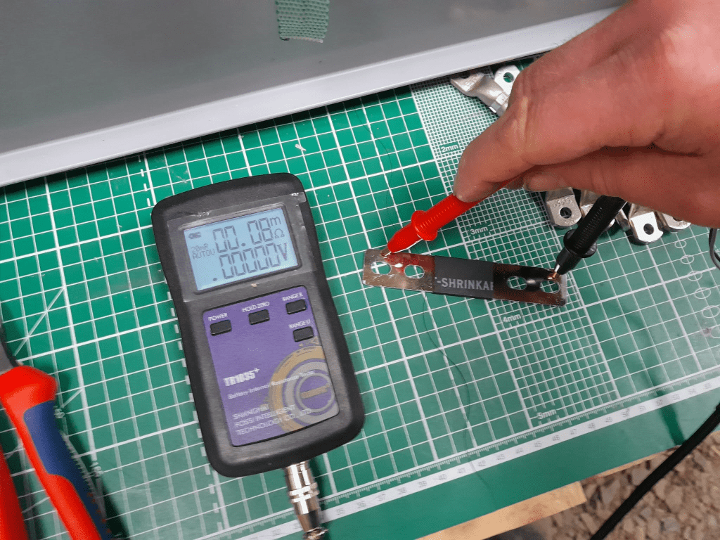
When measuring this with our trusty and highly precise TR1035+ the result displayed is 0.08mOhm.
Pre-built busbars 105mm * 20mm * 2mm
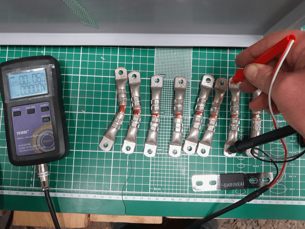
The Klauke version which comes with tinned copper lugs gives us a reading of 0.06mOhm – despite the smaller cross-section of 35mm2. The ideal internal resistance of the copper wire could be expected to be around 0.051mOhm (according to some other online calculator), so we are much closer to the measured value.
Custom busbar 105mm * 35mm2
The display error of the TR1035+ is expected to be similar as the measured range of both busbars is quite similar. There is certainly quite an amount of uncertainty (not only due to the maximum resolution of 10uOhm) to it. But it is interesting to see that the resistance of the custom busbars seems to be lower despite its smaller cross-section – while being better insulated (not seen on the picture) and more flexible at the same time (as it can be bent in more directions).
Producing these custom busbars is certainly more expensive (a single lug costs around 1.17GBP or 1.27CHF) and involves more manual and time consuming labour. However, it is quite easy to double them and/or increase its cross-section to up to 70mm2 per wire (when using multi-stranded DIN EN 60228 conductors).
So, this is it for today with fascinating facts about busbars for LiFePO4 cells.
Now, that we got our Toyota HiAce we thought it might be a good idea to add more power to the vehicle: in form of an 8s EVE LF280K LiFePO4 battery and a Victron MultiPlus Compact 24/1600/40-16 inverter/charger. In the following, we describe our setup and the reason why we built it like this.
The Requirements
The sustained output power of the inverter must be over 1'200W.
Charging via AC via EVSE or generator must be possible.
Charging via alternator must be possible (but is not the norm).
Charging of 60% of the battery (from 20% – 80%) via AC should take less than 180min.
The installation should use the minimum amount of space possible.
We should be able to use our existing Eve LF280K cells, thus limiting the overall current to 140A.
As the vehicle will not have a diesel heater, it should be possible to run a 150W infrared heater for at least 3 * (4+2)h = 18h (^= 2'700Wh).
In addition, the battery should be able to run a refrigerator with an average power consumption of 50W for at least 72h ^= 3'600Wh (next to other power consumption).
Design Considerations
With a maximum current of 140A and a cable run length of 1.5m, we should plan with a cross section of at least 35mm2.
Basically, with Eve LF280K cells we have three choices regarding the battery size:
1* 4s (“12V”) Configuration 4 * 3.2V * 280Ah = 3'584Wh This would lead to a required nominal AC charge power of at least 716.8W/h and a charge current of at least 56A/h.
2* 4s (“12V”) Configuration 2* 4 * 3.2V * 280Ah = 7'168Wh This would lead to a required nominal AC charge power of at least 1'433.6W/h and a charge current of at least 112A/h.
1* 8s (“24V”) Configuration 8 * 3.2V * 280Ah = 7'168Wh This would lead to a required nominal AC charge power of at least 1'433.6W/h and a charge current of at least 56A/h.
The Victron MultiPlus Compact xx/1600VA inverter/charger provides enough sustained power output (while being smaller than the non-Compact edition). Depending on the voltage of the battery, this will slightly impact the amount of charge current.
To charge the battery via the alternator we would need a DC/DC converter that depends on the battery configuration as well (either 12-12 or 12-24). So, let’s have a look at the battery first.
1* 4s (“12V”) Configuration
The smallest, lightest and cheapest configuration. But capacity requirements regarding the fridge are only fulfilled, if there are no other loads. In addition, the discharge current is relatively high (scratching the maximum discharge rate of 0.5C).
2* 4s (“12V”) Configuration
More complex setup, as each battery needs a separate BMS, which leads to the need of an aggregator for both batteries to correctly report SoC and calculate CCL and DCL. In addition, more cabling and fusing is required (and probably to a large bus bar). Comes with the advantage of having a redundant battery in case a single battery fails. Most expensive configuration.
1* 8s (“24V”) Configuration
Custom battery build needed, as there is not enough space for a typical 2 * 4 cells setup behind he seats. But, only a single BMS and thus less wiring is needed. Comes with a slight disadvantage of not having native 12V from the battery. This is actually not an isse, as all our DC devices also accept 24V. Cells can better balance voltage differences across a single 8s bank.
The Setup
In the end, I decided for the 8s configuration, due to less complexity. Splitting the 8s configuration across two cell blocks seemed to be an acceptable compromise.
As a regular MultiPlus 24/1600/40-16 would not fulfill my AC charge requirements, I had to decide to either add a second MultiPlus or to add a dedicated charger. I opted for a Phoenix Smart IP43 Charger 24/25 instead of a second MultiPlus. The MultiPlus in parallel would always consume 10W though most of the time I would not need the output power. Whereas, the Phoenix would only need power, when connected to AC. And reconfiguring the MultiPlus every time I charge was not an option for me. And yes, I lose redundancy – but also save some money (Phoenix is much cheaper). So, in the end the nominal charge power is 40A + 25A = 65A, which lets me charge at 1'560W reaching 60% within 165min.
The HiAce comes with a 70A alternator, so I chose a Orion-Tr Smart 12/24-15 DC-DC Charger. With this charger, I could run the engine in standby and still have the car heater running. And this is probably the predominant use case (if charging via alternator at all).
For the DC bus bar I went for a Victron Lynx Distributor, so I could use and install MEGA fuses. Having a 1’000A bus bar seems certainly overkill, but a separate bus bar and fuse box that accepts 35mm2 cable and MEGA fuses would be not be much smaller.
I changed the existing AC inlet of the HiAce to Neutrik PowerCON True1 TOP (congrats to the marketing department, I am still amazed how this name rolls of the tongue) and installed 2 Siemens compact 16A CRCBOs (external AC in, internal AC out). I am aware that theoretically I could support more than 16A on the internal AC out (via PowerAssist). If ever needed, I can replace the RCBO with a 20A version.
I added a VE.Bus Smart Dongle to the MultiPlus and opted against a complete (Raspberry-based) GX installation. The reason, I keep a USBMK3 with me anyway (in case I need to reconfigure the MultiPlus) and still have (Bluetooth) access to the most important settings and information of the MultiPlus. With the GX, I would to be running a WiFi hotspot (and consuming more energy as well). The disadvanage of not being able to use DVCC with information from the BMS is clear to me and accepted.
I selected a B2A8S20P JK-BMS that has an integrated 2A balancer and an RS485, CAN and heat port. In case, I ever add a GX device, I am still able to connect them and use DVCC.
The Specs
Nominal power (“capacity”) 8 * 3.2V * 280Ah = 7'168Wh
Maximum discharge power 1’600VA (1'280W, capped by the inverter) with a maximum current of 80A/63A/55A (at 2.5V/3.2V/3.65V)
Maximum AC charge power 1'560W
AC Charging from 20% – 80% in 165min
Maximum DC charge power 360W
MultiPlus self-power consumption 10W
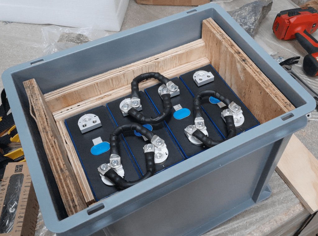
The Build
As mentioned before, due to space constraints I had to split the battery in 2 parts (with each having 4 cells). Instead of using utz RAKO boxes I used 12mm (sanded) plywood which I did not screw together but tied down with a banding/tensioning tool and a ratchet strap. With this setup, I can easily access und disassemble the cells if needed, while still having a sturdy case. Both cell blocks are connected with a (blue) Anderson SB175 connector.
The BMS itself is mounted to the side of one of the cases (I took extra care to use short screws, in order not to drill into the cell casing). I used M6 Weidmüller 35mm2 90° angled compression cable lug to get the wire away from the BMS and into the bus bar. All other compression cable lugs are DIN 46235 from Klauke (M6 35mm2 on the cells, and M8 16mm2/35mm2 on the bus bar).
The AC and DC wires are all Eland H07RN-F (except for the last two points):
Charger to bus bar, battery to bus bar: 35mm2
Cell block to cell block: 2 * 35mm2
Alternator to DC-DC converter, DC-DC converter to bus bar: 16mm2
External AC in to RCBO, RCBO to inverter/charger (both directions), RCBO to internal AC out: 3G2.5mm2
For the connection of the Inverter/charger to the bus bar, I used the Victron installed 25mm2 welding cables.
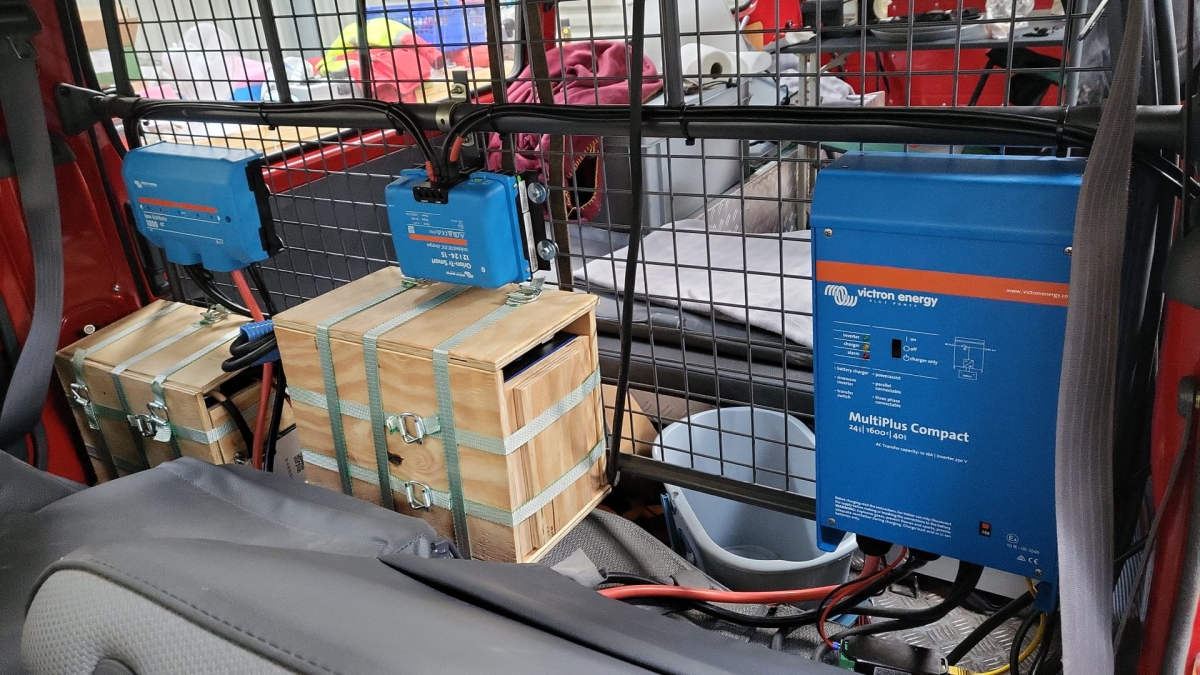
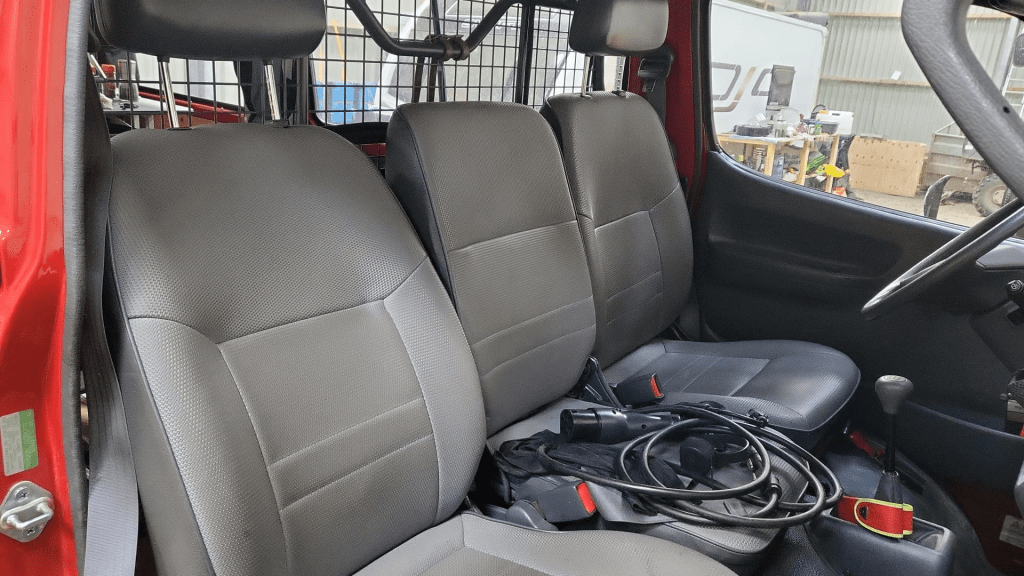
Images
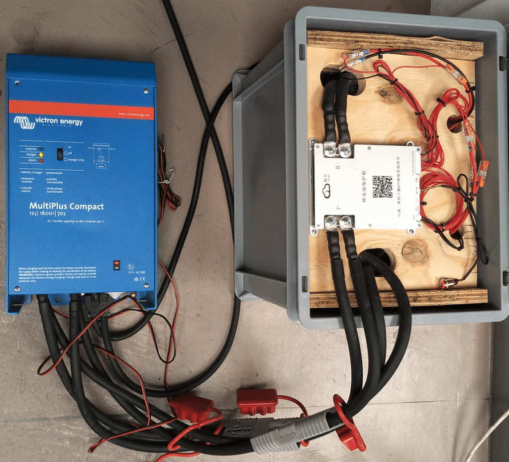
The installation is barely visible behind the seatsView from the back with preliminary wiringConnection of cell blocks with SB175 connectors, cell block 2 and DC-DC converterLynx Distributor with cell block 1Inverter/charger with space for second charger and cell block 2 (left)
Note: the Phoenix charger is not visible on the images, as I am still waiting for it to be delivered.
Charging via EVSE
Conclusion
We now have more than 7'000Wh of additional energy without losing any storage space for roughly 2'850 CHF/2’500 GBP (parts without labour). We can survive an extended weekend of 72h without recharging while still being able to enjoy amenities as using a coffee machine, heating and refrigerator. In case of longer periods of usage, we can recharge at any EVSE, or via shore power. And in emergencies, we can also charge via our Honda EU10i or via the alternator of the vehicle.
The battery is placed directly over the engine which helps in cold weather conditions to easily warm up the batteries to a chargeable level.
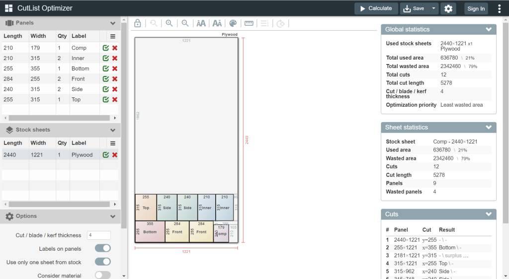
For this build, I planed all the boards after cutting, before putting in the cells. With this, I hoped to minimise the chance of any particles on the board damaging the cell insulation.
And for the small board at the short side of the case, I did also use 20mm plywood, but planed it several times until it I could just slide it in.
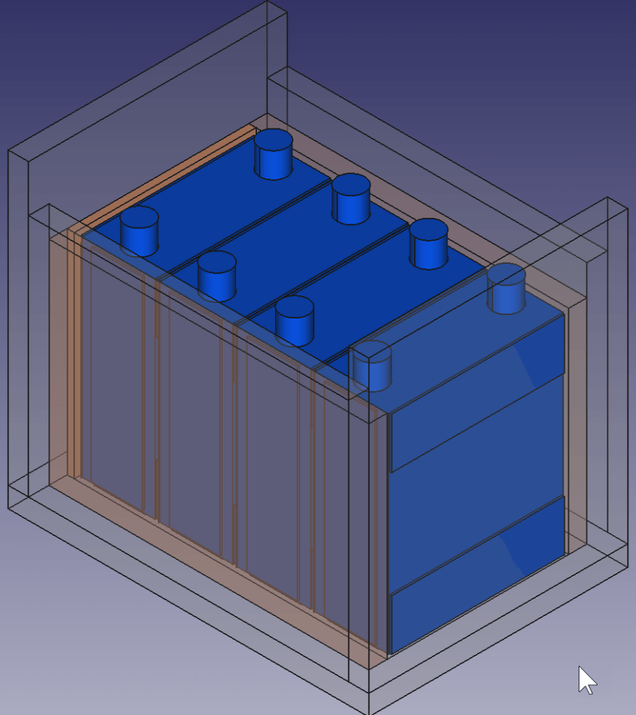
This is how the wooden case looks with the cells and insulation boards (shown in red):
Top view: battery cells with depicted insulation boards (shown in red)
Note: when using a JK-BMS I found it important to have the main negative connection point on the upper left (or lower right). Only with this orientation it was (relatively) easy to connect the cell to the BMS.
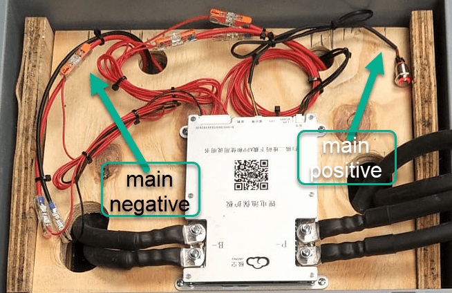
BMS connected to cells
It needed some fiddling to get the main negative cable pair to the BMS and the main positive cable pair out of the frame, as we can see from the image above.
The connection to the individual cells are fed through WAGO 221-2411 2 conductor inline splicing connectors. The holes into the top board were done with a forstner bit and a jigsaw. This version of the BMS can be fixed with four screws to the board (so no need for wire straps as with the 24s version).
Again, instead of a display I just used the pluggable power button that is connected to the display port of the BMS to power on and off the device.
In the end, I added Anderson SB175 connectors and 1383 (2AWG) contacts to both pairs and connected them to the inverter.
cell contacts were secured with M6 serrated washers and M6 16mm steel bolts;
BMS threads B- and P- were secured with M6 lock nuts to M6 16mm steel bolts (with the bolt upside down);
cell wires from the BMS were fitted with uninsulated ferrules;
cell wires on the positive cell poles were fitted with ring lugs and a 2.5mm2 hookup wire;
I added handles to the SB175 connectors to facilitate disconnecting the cable pairs;
I added dust covers to the SB175 connectors;
all compression cable lugs and the SB175 were crimped with a Hilti NUN54-22;
all cable lug connections and Sb175 were heat shrinked;
I added 2*35mm2 cable pairs with SB175 connectors to the inverter by replacing the existing 35mm2 welding cable with M8 lugs (you still need M8 lugs on the inverter positive and negative terminals).
Things to improve next time
Mount the SB175 connectors to the outside of the container With this the lid can be closed and the cables and BMS are better protected against pulling;
add 3A inline fuses to the cell wires;
use 45° angled cable lugs for main positive and main negative to make it easier to get the wires routed outside the container;
feed an additional wire pair for the voltage sensor from the main positive outside the container to be able to connect it to the inverter (but I am not too sure about this, as I think the voltage drop on the 2*35mm2 connection is neglectable – it might better to add a temperatur sensor to the main positive):
add a Victron MK-3 USB-C interface with RJ-45 cable into the case (to be able to restrict AC power on the inverter).
What did it cost?
Cost calculation for the 4s battery including case and inverter
Summary
This case is not as complete as the 8s version – due to its form factor. Neither the inverter has an RCBO nor the battery has a DC MCB. This has to be added separately (incurring additional cost and space). As written above, the 4s version is more like a traditional battery. However, the form factor is quite compelling; 3.5kWh in 400mm x 300mm x 325mm case. Especially in combination with the compact edition of the Victron MultiPlus. And the cost (as always without labour) is very reasonable, as well.
The inverter delivers 1200W constant power – in my opinion, enough for a small and mobile electricity build. Runnig a Krups Inissia Nespresso machine is not a problem, and boiling water with our 1000W immersion heater neither. Worst case, you could also run a 300W infrared panel heater for more than 11 hours.
One drawback of the inverter is probably the relatively small charger. With 70A at 12V it can only charge the battery with around 840W. This is certainly not the problem of the battery which would support charging up to 1344W.