Current state of our electric installation

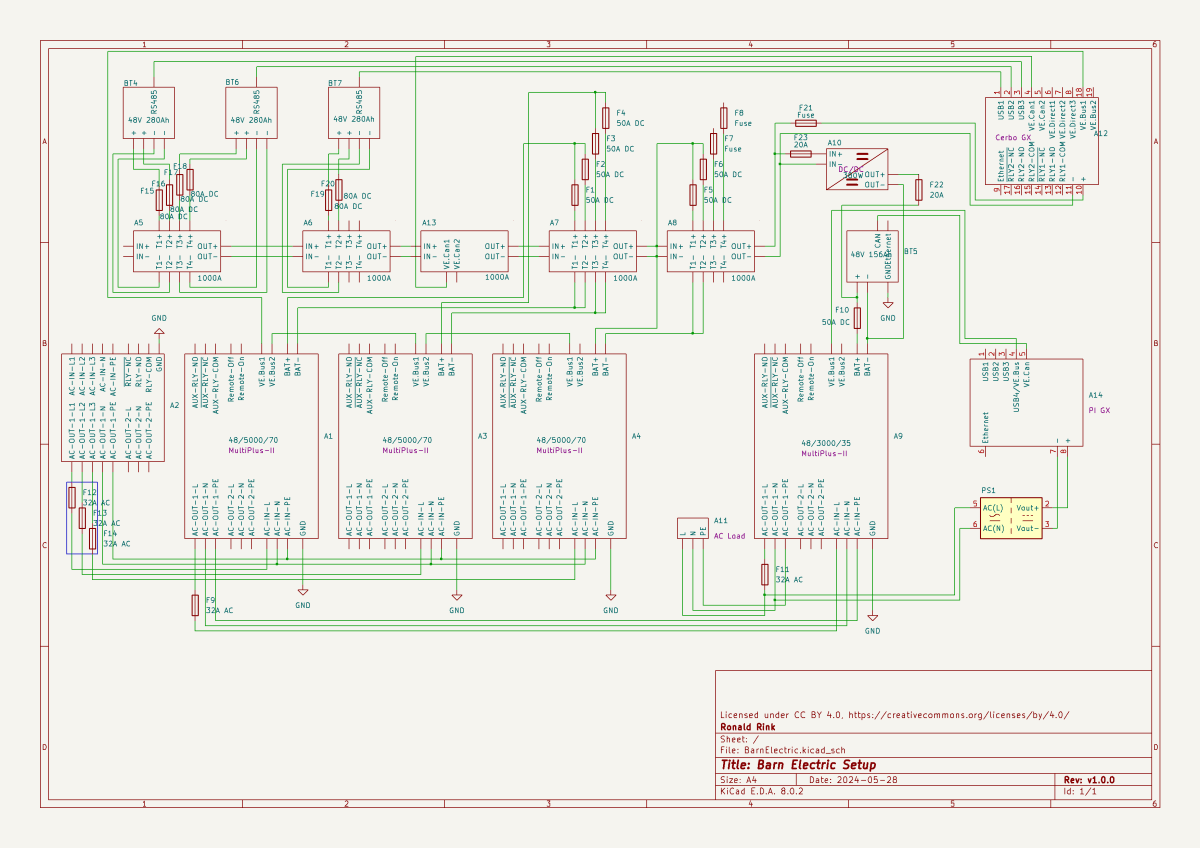
I recently wrote about our upcoming solar PV adventure. But before updating our system, I thought it was time to document and explain our current setup (with the help of KiCad).

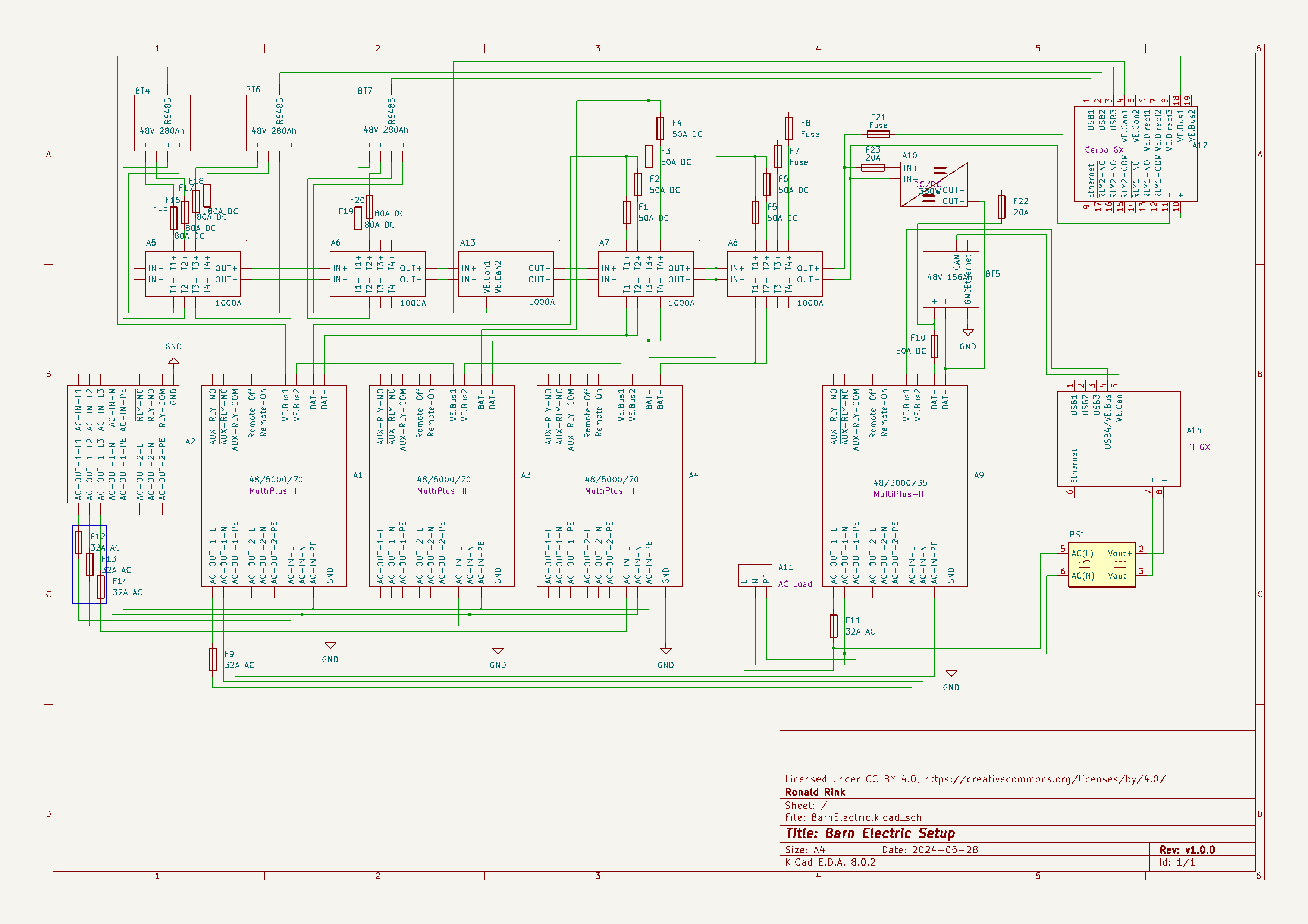
This system is the main electricity for our barn and currently consists of three batteries with an energy (often referred to as “capacity”) of 3* 14.33kWh = 43kWh (battery bank A, A1:A2 on the plan). These batteries are charged by a JCB G20QS (B1) via three MultiPlus-II 48/5000/70 inverters/chargers (B1:C2) which are by default in “Charge Only” mode. The MultiPlus-II are configured in a 3-phase configuration but only turned on when 3-phase is actually needed.

The main power is delivered by a MultiPlus-II 48/3000/35 (B4:C5) that is connected to a separate battery bank (battery bank B, BYD LVS Premium Battery-Box with an energy of 8kWh). This latter MultiPlus-II is connected to L1 of the 3-phase MultiPlus-II. So, whenever the main batteries get charged the cascaded inverter will also be charged. In addition, we can then use PowerAssist to up to supply 8'000VA (= 5'000VA + 3'000VA) when running on batteries and up to 14'500VA (= 6'500VA + 5'000VA + 3000VA) on a single phase.

Though the generator can supply up 14'400W the chargers of the Multiplus-II can only charge with a power of up to 3* 48V* 70A = 10'080W. This is actually an advantage as the optimal efficiency factor of the generator is roughly at 12'000W. So with 210A we are pretty close. If we ever added more chargers to the system we could even slightly increase the charge current to 250A.

System A with the 3-phase inverter configuration is connected to a Lynx bus bar (A1:B4) that also includes a Lynx shunt (B3) used for measuring over all batteries. In addition, there is an islolated Orion-Tr DC-DC charger (A5) that constantly feeds system B.

System A and B are connected to their separate GX:

  • system A
    Cerbo GX, A5:A6
    MultiPlus-II via VE.Bus, Lynx Shunt via VE.Can, JK-BMS via RS485/USB
  • system B
    Raspberry Pi4 running VenusOS, B5:B6
    MultiPlus-II via VE.Bus, BYD BMS via VE.Can (on a Pi GPIO Hat)

And this is it for the electricity installation in our barn.

Note: This cascaded setup is officially not supported by Victron, but it has been working for us without problems for months now. This might be different in your case.

Configuration of electric components

Addendum

./.

Corrigendum

./.

Building a battery case for an 16s Eve LF280K configuration

The other day, I realised that I never wrote about the case build of our 16s 48V batteries, as I did for the 8s case and the 4s case. So, here it is – and I am actually describing 2 revisions as we made some adjustments.

First, the total weight of the cells alone would be roughly 16 * 5.3kg ~ 85kg. This is way beyond what a single person can – or at least should – lift. So, I deciced to split the battery into 2 separate cell blocks of 8 cells each (similar as I did split the 8s battery in the Toyota HiAce). With this approach, I would be able to:

  • reuse the 8s design (including the RAKO boxes)
  • be able to move or lift half a battery (which weighs roughly 53kg)

This battery has a nominal capacity of 3.2V * 16 * 280Ah = 14'336Wh and can be charged or discharge with up to 140A ^= 7'168W. We currently have 2 of these batteries running on our 3-phase setup with 3 * Victron MultiPlus-II 48/5000/70-50.

So essentially, I built 2 8s batteries with a connection cable between cells 8 and 9. The main negative and the BMS would be in one box and the main positive with the DC breakers would be in the other box. To avoid confusion, in this setup I went for coloured Anderson SB175 housings, with

  • Red
    2 * 35mm2 H07RN-F cable main positive
  • Grey
    2 * 35mm2 H07RN-F cable main negative
  • Blue
    Interconnecting both blocks
    2 * 35mm2 H07RN-F cable connecting from cell 9 positive to cell 8 negative

In all cases

16s Battery Connectors

To connect the cells to the BMS balancer cables I extended the balancer cables with 2.5mm2 wire via WAGO 221-2411 inline splicing connectors. I then measured the increased resistance of the additional cable length and adjusted the values in the BMS configuration for cells 1 to 9.

With these inline connectors I am now able to disconnect the blocks from each other so I can move them around independently, if needed.

On the BMS, I connected a USB RS-485 TTL adapater with a USB extension cable which leads to one of the USB ports of the Victron Cerbo GX. With the help of dbus-serialbattery and BatteryAggregator I can control the DVCC settings in Venus OS.

The rest of the build is, as I already mentioned, pretty much like the 8s build.

Revision 1

Here are some images of the completed build of revision 1.

16s Battery top view
16s Battery Block 1 main negative with BMS
16s Battery Block 2 main positive with DC breaker

Revision 2

These are the changes I am currently making for the next revision:

  • add additional connectors for the balancer cables to further facilitate the disconnection of both blocks;
  • use 16mm2 M6 Klauke DIN46235 compression cable lugs for the connection of the main negative (cell 16) to the B- of the BMS (only relevant to the older JK-BMS), to be able to disconnect and potentionally replace the BMS;
  • use a WAGO 35mm2 DIN rail connector in the main negative block on cell 1/9 for the outgoing cable;
  • use cable glands on the external connections;
    (this allows for easy disconnection and re-building the block as an 8s battery);
  • use ratchet straps for compressing and mounting the cells to enable easier maintainability of the cells;
  • use Anderson PowerPole PP180 connectors instead of SB175, so I can use mounting plates for the PP180 and do not have dangling cables on the outside of the case
    (these connectors are expensive and increase the price of the overall build by roughly 60GBP).