Some years ago, we bought a Autoterm 2D diesel heater with a waterproof box. This heater actually needs an external 12V power supply (or a 24V power supply, depending on the model you buy). Until now, we always connected this to one of our 12V leisure batteries. That meant we always had to carry a long 12V extension cable with us. Not any more …
Since we had such a good experience with our mobile shower via USB-C that originally also runs on 12V, I went looking for more devices with a 3A @ 12V power requirement. And according to the data sheet Autoterm 2D just is such a device. The manual states a power requirement from 10W (min 800W heating power and 34m3/h) to 29W (max, at 1800W and 75m3/h).
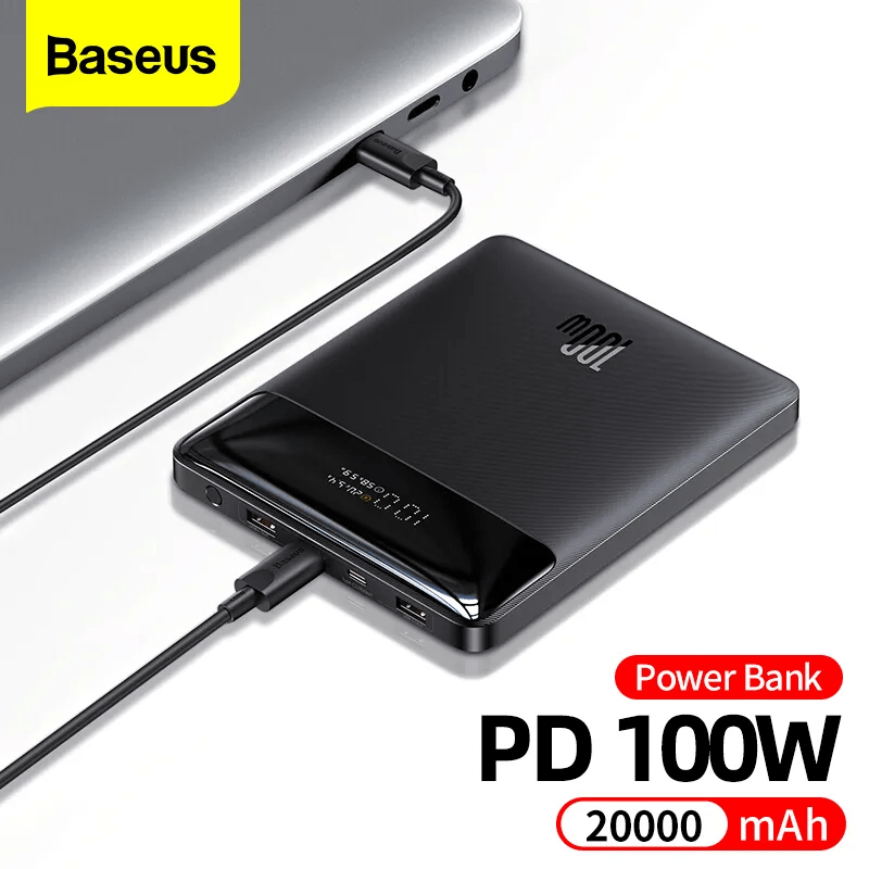
So, I got myself a Baseus 100W Power Bank 20Ah from Aliexpress that can deliver the required power. With this unit the diesel pump can be powered for approx 2.5h at full capacity and approx 7.5h at minimum capacity.
Actually, any power bank with USB-C PD that delivers 3A @ 12V could be used. And if you take a power bank with a higher capacity the heater will certainly run longer.
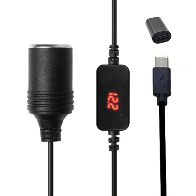
USB C PD Type C Male to 12V Car Cigarette Lighter Socket, taken from Aliexpress
In my opinion, the advantages of this approach are:
Flexibility: we can carry the power bank along with the heater and do not need to keep a 12V power source (leisure battery or else) nearby. An option to power a power bank is probably easier to find than a 12V source. Especially true for our trailer with a 24V battery.
Price; power bank is around 51CHF and the converter 5CHF (and the battery 1700CHF) . Compared to the other heater we have, the Profidurium Mobile-Heater 2kW, this is much cheaper. The additional battery with charger costs an additional hefty 970CHF (on top of the 2300CHF for their heater).
Weight: 400g for a power bank is a neglectable additional weight compared to a full blown battery.
The other day, I connected my BYD Battery-Box Premium LVS 8.0 to a Victron MultiPlus-II 48/3000/35-32. Here are the steps I took to do it and some errors I ran into.
The Battery-Box needs to communicate via CAN with the inverter. And as Victron inverters do not come with a CAN port by default (unless you go for a MultiPlus-II GX or EasySolar-II GX) we need a GX device. Originally, I wanted to use my Victron Cerbo GX for that, but since we moved into the caravan the device is gone missing. Luckily last year, I supplied myself with a couple of Raspberry Pis (at least model 3and 4 are supported) that could run a Venus OS and act as a GX device. And as I was not the first one doing that, I thought it would be just too easy – well, it was easy after I did everything right.
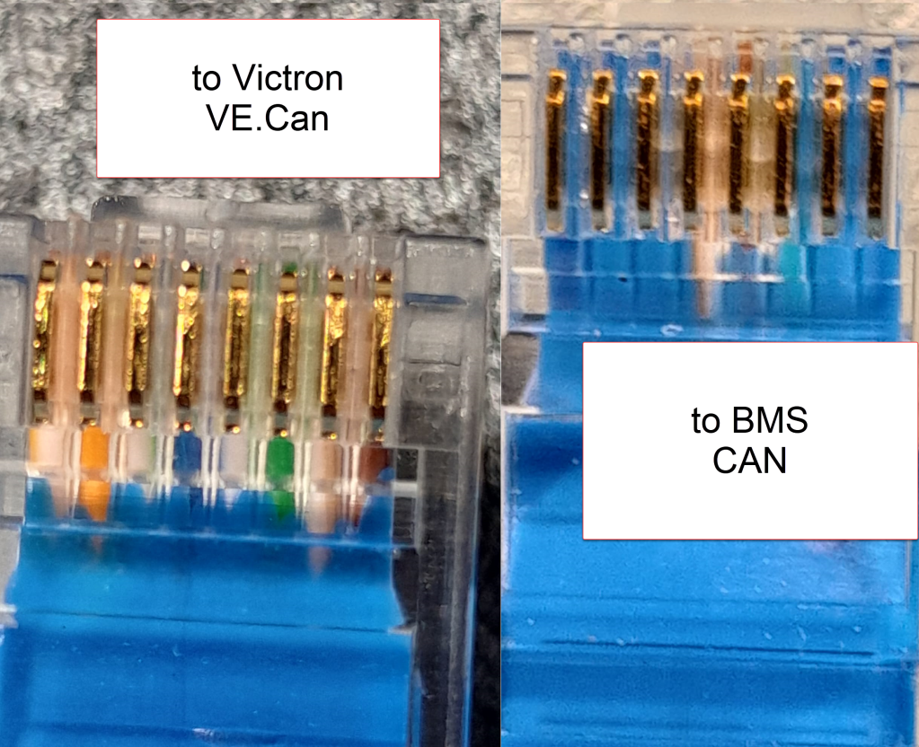
Normally, Victron requests to use a VE.Can to CAN-bus BMS Type A cable to connect to a BYD battery. This is actually an ordinary CAT 5e network cable with RJ45 connectors where only the relevant CAN pins (and GND) are connected.
In order to screw the wires to the CAN hat terminal, I used uninsulated ferrules. Otherwise the Cat 5e wires would have been too soft and light for the terminal.
Installing Venus OS on the Raspberry PI 4
For the Raspberry PI 4, I followed the documentation and installed the standard (and not the large) image. At that time, v2.93 was the newest version (see here for directory of all versions). I uncompressed it and used Win32DiskImager to write the OS to a MicroSD card (all done on a Microsoft Surface Go2 running Windows 11).
Note1: at first, I did the install with a Raspberry Pi 3 Model B V1.2 which also worked fine. However, the CAN device on the Victron UI then did not show any packets but worked without problem.
Note2: The Raspberry Pi 4 is a model B Rev. 1.5 (I mention this, as I saw comments that indicated that there might be a difference between different revision from 1.2 onwards).
Note3: I activated the “Mobile” tile to be able to change the charge current via the overview screen.
The CAN driver then had to be installed separately. As I did not have direct internet access from the Pi, I used the offline install method with a USB memory stick.
As written in the documentation, I copied the compressed installation files as venus-data.tar.gz to the root of the USB drive and restarted the Pi. To verify the automatic installation was successful check if there is a new menu item Package manager at the end of the Settings list. If not visible check if you can find SetupHelper in /data. You can always manually copy it from the SDCard (use mount to see where the card is mounted) and then run setup yourself. I did a reboot after every package.
New menu item in Settings after installation of SetupHelper
Same procedure here. Copying the compressed installation files to the SDCard as /venus-data.tar.gz. Then run the package installation manually if for whatever reason the automatic install does not succeed. See below what the package manager should look like after the installation of both packages.
List of active packages in Package manager
Installing the driver
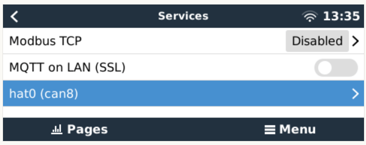
Configuring the driver had to be done from the terminal. There was a minor issue for me which I did not get right the first time. When asked to install an interface via the i option I actually had to type in a hat. I named the device hat0 and after the reboot it showed up as hat0 (can8) can8 spi0.0. In my case it was the “Waveshare 1-channel CANbus Hat 12 MHz crystal” (check the imprint on the silver part on the hat to see the crystal speed).
Configuring CAN bus
There is really not much to configure. The only option under “Services” is to set the communication speed which is 500kB/s for BYD. If the CAN adapter does not show up make sure the correct type has been selected in VeCanSetup. For me it just worked out of the box.
CAN hat showing up in ServicesSetting the CAN speed for BYD Battery-Box BMUConfigured CAN bus
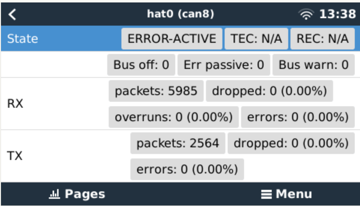
Before the BMS is connected the CAN should show up as ERROR-PASSIVE. As soon as the communcîcation worked it changed to ERROR-ACTIVE.
CAN bus ERROR-ACTIVE with actual traffic
Note: When I tried with the v2.93 on the Raspberry Pi 3 the RX/TX counters were always empty (but nevertheless worked). Via ifconfig the packets were correctly shown. But with the Pi 4 traffic was shown on the UI right from the start.
CAN bus traffic via ifconfig
I did not connect the CAN cable at that point but configured the Battery-Box and the inverter first.
Commissioning the inverter
I used a USB MK3 adapter with an RJ45 Cat 5e cable connected to the VE.Bus of the inverter to configure the MultiPlus.
I used VEConfigure 3 and VictronConnect (to be able to configure via VictronConnect I had to use the zzz password to get out of the read-only mode).
First, I updated the firmware of the MultiPlus via VictronConnect and then continued with VeConfig.
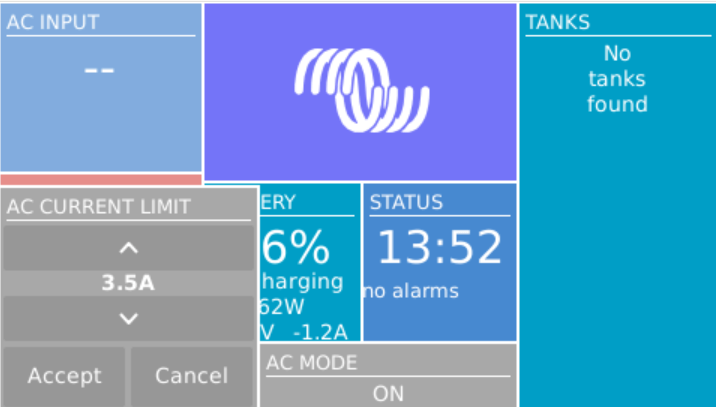
Basically, I set the inverter to off-grid and did not enter a country code. For the battery type I selected “Lithium Iron Phosphate” and accepted the default settings. I set the “AC current limit” to a maximum of 20A (the maximum my generator could handle) and activated the option to have it overruled by “Remote” (which can also be done via the GX Remote Console or VictronConnect).
Setting AC current limit via GX remote console
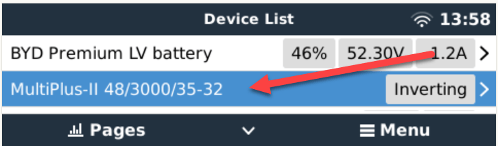
I also activated DVCC to later have the BMS tell the inverter when to charge and how to discharge. This was pretty much it. So I connected the MultiPlus via the VE.Bus and the MK3 cable to the Raspberry where it showed up instantly.
Inverter shows up after connecting VE.Bus to the Raspberry via MK3
Commissioning the Battery-Box
After assembling the battery which conisted of only stacking both battery modules on top of each other followed by the PDU on the very top I connected the BMU via the grey RJ45 to the PDU. After turning on the top most battery the BMU started as well and I was able to connecto to the WiFi of the BMU from the BeConnect app (Android or Windows both worked for me, the latter actually showed more information).
Via the app I pre-downloaded a current firmware and after switching to the BYD access point I applied the firmware (actually two different firmwares). After some waiting the new firmware had been applied and I could configure the basic settings: inverter manufacturer, number of battery modules.
At this stage I connected the 35mm2 cables from the battery to the inverter. I bought the cable preconfigured with the battery. And I used a Littelfuse JLLN-125X (class T) as a fuse between both devices.
Connecting the battery to the Venus OS
And then I connected the BMU to the GX. After some seconds, the inverter clicked and started charging. Essentially, DVCC turns on automatically (even if turned off before) as soon as the CAN communication is established.
In the GX overview the battery appeared and gave some additional information (see next section for details). All parameters between battery and inverter were exchanged automatically.
Things I noted
The battery turns itself off after a while when no communication via CAN is possible. This behaviour is described somewhere in the BYD manuals.
Charging the battery does not work when no CAN connection can be established. The inverter stays in “Absorption” mode with a current of 0A.
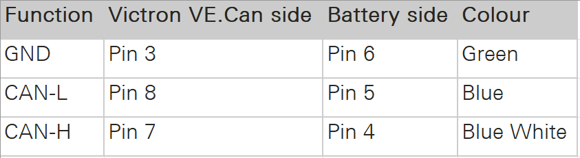
A more detailed description of the pin layout can be found on the BYD manuals. See images below.
The GND pin is not required for communication between the BMU and the VE.Can GX. Only BLUE for CAN-H and BLUE-WHITE for CAN-L are going into the CAN hat.
In addition to the official web site bydbatterybox.com the web site eft-systems.de provides additional information and downloadable documentation.
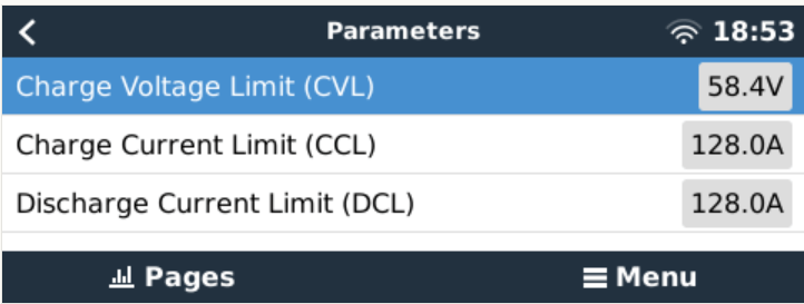
When charging the Battery-Box for the first time, I eventually reached a 100% SOC. Until that point the charge current stayed nearly constant at around 30A (Bulk). It decreased to around 1.2A and the inverter turned to “Absorption” but never stopped charging. At some point one of the cells reached a voltage of over 3.7V which resulted in a warning on the GX. Nevertheless, charging continued. I manually switched off the charger after the second time I received a warning due to high cell voltage. I would have expected to have the inverter automatically stop charging at a 100% SOC. Maybe the BMS only measures the charge voltage limit (CVL) which is defined as 58.4V and not the individual cells?
The cells in a battery were not really well balanced (delta >= 100mV). I would have expected a better balancing. Actually, I do not know if the BMS has a balancer at all. I could not find anything in the documentation.
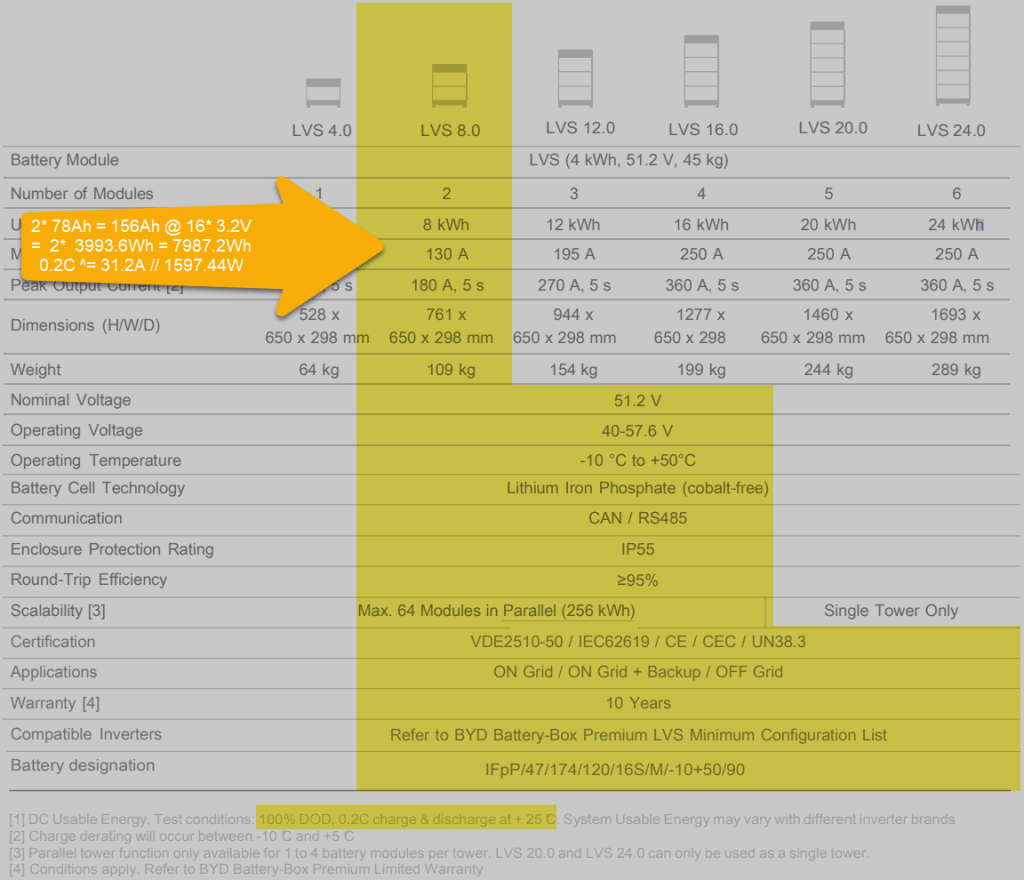
Each LVS 4.0 has a capacity of 78Ah @ 51.2V = 3993.6Wh. The GX shows this information in the “Details” item within the battery. I could not find this information in the manual.
The BYD manuals state, that the lifetime of the battery can only be achieved at 0.2C, which limits a single LVS 4.0 to 798.72W (or 1597.44W for a LVS 8.0) – this is a ridiculous small amount.
Charge current was initially restricted to 38.4A by the battery, only after a day or so, the charge (CCL) and discharge current (DCL) went up to 128A. In my case the inverter only support 35A max, so no issue with that.
Startup sequence Start top-most battery first by pressing the power button for a couple of seconds; then start the BMU if not automatically started; next start the inverter; then start the GX (in my case currently on the AC side).
Shutdown sequence Turn off the inverter; turn off the BMU; turn off the individual batteries (keep buttons pressed for a couple of seconds); GX turns off automatically.
Adding a CAN hat in VeCanSetup needs to be entered literally as a hat.
Though I set the AC charge current to 20A the inverter only drew 16A at most.
The WiFi of the BMU cannot be changed, nor the password.
BYD RS485 CAN pin layout, taken from the BYD BMU maualBYD to Victron CAN pin layout, taken from the BYD BMU manualBYD Battery-Box voltage and charge limitsSpecification of BYD LVS 8.0, taken from the BYD manuals
Future improvements
I want to connect the Raspberry to the DC side with a 48V/12V step-down converter and a 12V to USB-C adapter. Inbetween I want to add a power bank, so the GX can be configured even if all power sources are down.
Replace the CAN hat with a USB CAN adapter
Strengthen the connection of the CAN wire to the CAN adapter
All in all, the installation was straightforward. A couple of uncertainties are probably normal when doing this the first time. I would have expected more documentation (articles, videos) for this to be around. But I could not find anything for a BYD, Victron, VenusOS via Raspberry setup. Maybe others are only using a Cerbo GX?
The batteries are well built (all IP55) but extremely bulky and pricey. With around 400 CHF per KW this is more than 300% of regular LiFePO4 cells. But nevermind, lead and delivery times are in the magnitude of months.
I would have liked the BMU to be integratable into one of the PDU boxes. Now it is just hanging around separately.
Would I buy another Battery-Box? Probably not – too pricey. But good for starters. Plug and play when used with Victron and a Cerbo GX.
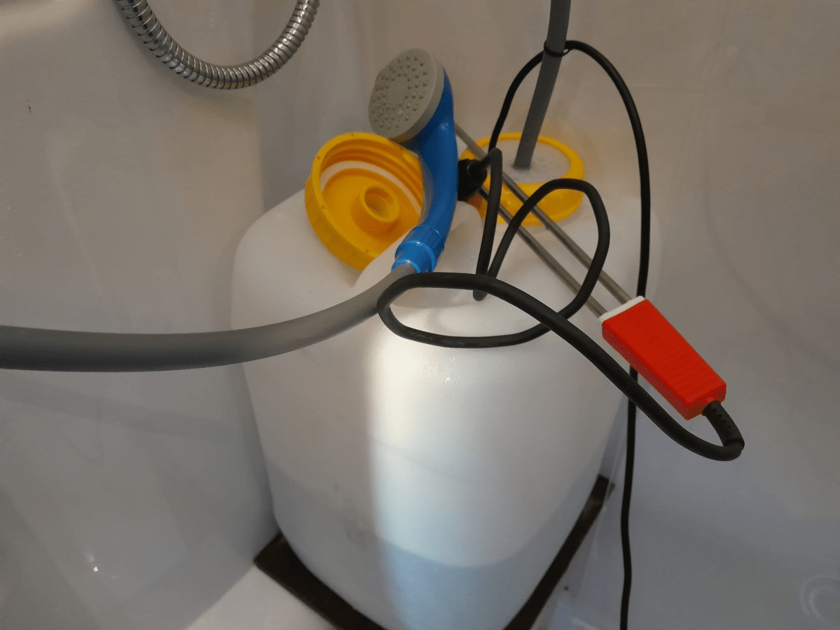
We currently use the shower, Brunner Aquafresh 2.0, in our Caravan instead of the built-in shower with the boiler to reduce the risk of legionellae and to conserve power.
We heat the water with a 2000W immersion heater which takes around 25min to heat the water to 43°C from 15°C (see the post linked above for more details on time and power requirements). And make sure to stir the water after heating before use.
The water is kept in a DIN96 20l wide-neck container from Comet with a special dust 2-hole cap to fit the hose and the elecitricity cable into it. The pump itself has a standard 12V car/cigarette plug that connects to a USB-C trigger board that takes it power from a USB-C power bank with Power Distribution (PD) 2.0.
Everything is kept within a 30mm PIR tube and glued together with hot glue. This does not look to nice but it works. To further “water proof” the device I keep it in a plastic zip-lock bag with the opeining upside down. See below for an even easier option for this.
The on/off-switch on the shower itself is not waterproof – but until never got too much water to produce a short.
To actually get the hose and the electricity cable through the plastic cap of the container I cut away the switch (as it could not be opened) and connected a new one (from Steffen, bought at Landi for 1,50 CHF).
The power bank must be able to deliver 3A @ 12V (the pump has a nominal power consumption of 35W). Water pressure is ok, but not great. Two people can consecutively shower from a 20l container (without washing long hair, of course).
Video: Quick review of our 12V USB-C mobile shower
We also use it in our cars as a mobile shower. On the road we only have a 1000W immersion heater, so heating up the water takes twice as long. But in the summer the initial temperature is much higher so it slightly compensates the total time needed.
UPDATE: instead of going through the hassle to build a USB-C to 12V converter yourself, you can also buy this item from Aliexpress. It is a sealed USB-C to 12V converter. It is much smaller than the tube-based device and costs only around 5CHF, but has no fuse.
Note, that there is a version with and without converter. I went for the version with the converter and with a cable length of 300mm.
USB C PD Type C Male to 12V Car Cigarette Lighter Socket, image from aliexpress.com
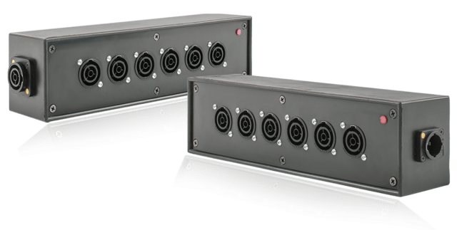
Recently, when I converted most of my electrical sockets and connectors to Neutrik powerCON True1 TOP, I was looking for a Neutrik power distribution. After some failed tests to build a box myself from an junction box, I found a product called Mini Brick from an italian company called Valentini which was sold via Distribution Zone in the UK for a retail price of 145 GBP (174 GBP incl VAT).
The box is essentially a 6-way (and not 7-way as shown above) power distribution rated up to 3500W (nearly 16A @ 230V) and has a red status light to indicate if it has power.
Build quality is very good (metal or hard plastic case, rubber coated); and the price is also understandable, as the chassis connectors alone would cost around 60 GBP. However, I was not totally happy with it due to is relatively massive form factor: L80mm x W75mm x H300 mm plus connectors.
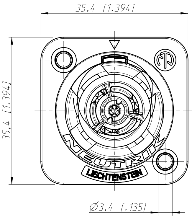
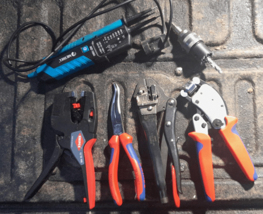
To cut the holes for the chassis connectors into the case, I used a Hilti 30mm hole saw with my Wabeco drill stand. Drilling the duplex chassis connector obviously needed 2 holes and a cutting away some excess plastic (later on I found out that a 25mm diameter is better suited for the smaller part of the duplex connector):
Opening for the Neutrik NAC3PX-TOP duplex chassis connector
Note: one might be even able to use 29mm and 24mm holes, see the detailed drawing – maybe I try this next time.
To mount the chassis connectors onto the box, I used M3 screws and hex nuts (I could not find TX versions) which I drill with a 3mm Hilti HSS-Cobalt drill (yes, overkill – but the only drill I had at hand). Unfortunately, the screws were a slightly too short, so it was a little bit of fiddling to get the hex nuts onto to the screws.
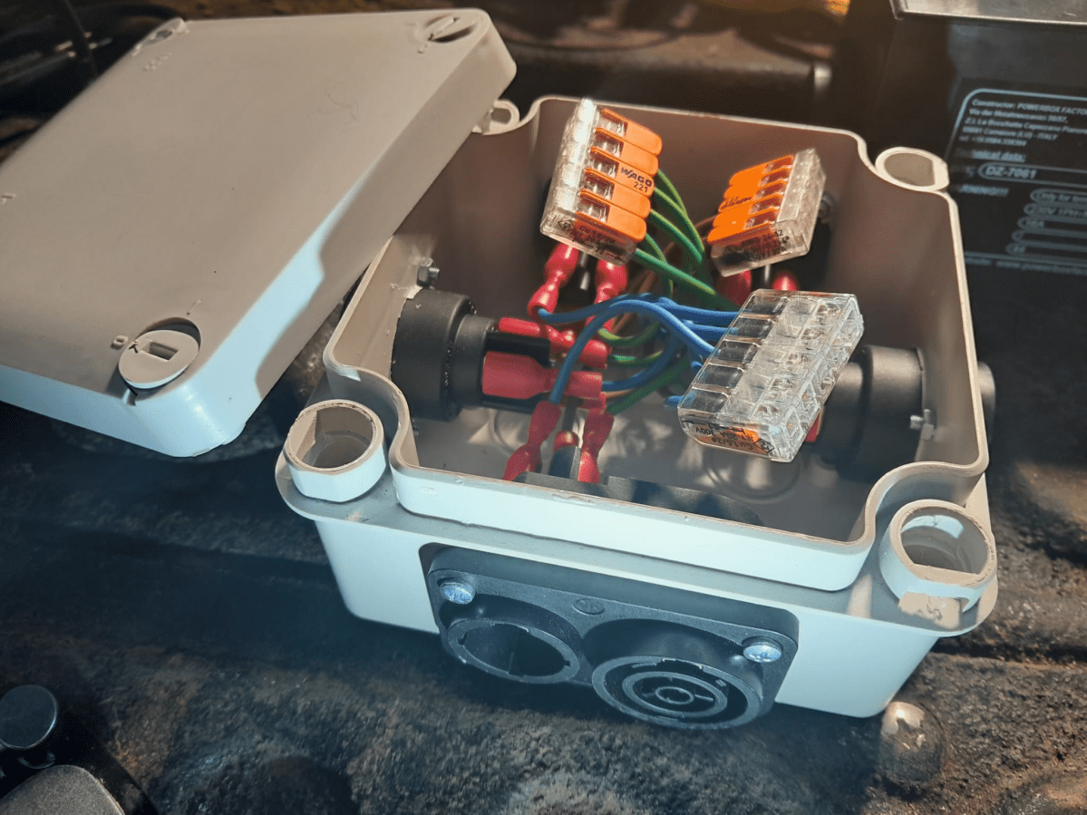
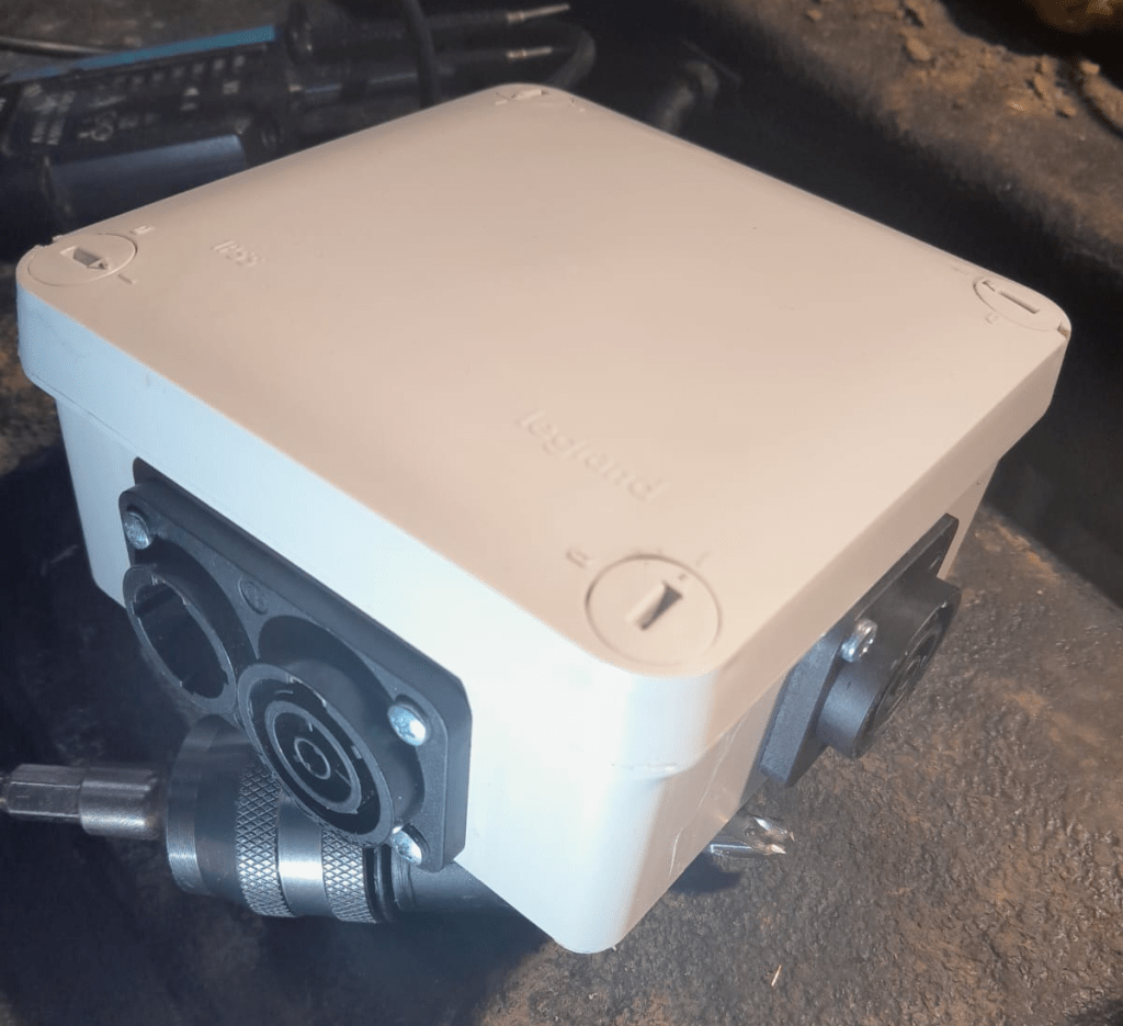
After all the Neutrik connectors were installed, I wired them to a 5-way Wago 221 COMPACT series splicing connector (221-415) with fully insulated blade receptable connectors (1.5mm2, 0.8mm, 6.35mm) to the socket and with 1.5mm2 ferrules to the clamp.
After assembly I did a final connectivity test to ensure all wires (L, N, PE) were correctly connected. As the duplex connector has a different wiring layout, it is easy to mix things up (PE is in the middle and not at the side).
5-way Neutrik powerCON True1 TOP distribution in a LeGrand Plexo junction box
The end result is not as sturdy as the Mini Brick, but much lighter and smaller. And if I ignore the amount of labour I put into the build, this box is certainly much cheaper.
Video: 5-way Neutrik powerCON True1 TOP distribution box made from LeGrand Plexo
And as usual: electrical installations can be dangerous – only have them performed by qualified personnel.
I am not the first and probably not the last, either. With leisure batteries becoming larger and larger, fuel becoming more and more expensive and the EV charging network better and better, I thought it was time to rethink charging leisure batteries in campervans, mobile homes and the like.
As I restrict the charging of my EVE 280Ah cells to 125A, the maximum power to charge with is either 8* 3.2V * 125A = 3200W for a 8s 24V battery or 16* 3.2V * 125A = 6400W for a 16s 48V battery. But as of now, I only plan for 24V batteries in our vehicles. This means, that even with the lowest single phase Type 2 charger in a EV charging station we get more power (16A * 230V = 3680W) than the battery can be charged with.
and a single phase Type 2 socket to a Swiss T23 socket, which they call a “bike adapter” – this comes in handy at charging stations with a 3-phase Type 2 cable.
As a 24/3000 MultiPlus-II (or EasySolar-II) does only support charging of up to 70A (resulting in a nominal charging power of 24V * 70A = 1680W), we would still be 55A “short” of the desired maximum charge current of 125A. With the EasySolar-II GX or the MultiPlus-II GX there is no 24/5000 version and the MultiPlus-II 24/5000 uses considerably more power (18W vs 13W) and is way heavier (30kg vs 26kg [including MPPT charger] vs 20kg). In addition the inverter would be massively oversized as the maximum expected inverter power would be limited to 8* 3.65V * 125A = 3200W (^=4000VA), anyway.
So, I came to the conclusion the least expensive and space/cost-efficient solution would come in the form of a Victron Skylla-TG 24/50A Charger:
So, with the combined power of the EasySolar-II and the Skylla-TG (70A + 50A = 120A), I can now theoretically charge at 8 * 3.2V * 120A = 3072W – near the maximum supported power. As the charge current will probably reduce at around 80% SOC, my 24V battery can be charged from 40% to 80% within one hour – at a price of less than 30p per Kilowatt (or 90p the hour)!
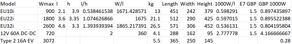
Here a comparison with some smaller generators:
a Honda EU10i will deliver 900W with 0.538l (around 1671W/l or 0.598l per 1000W)
a Honda EU22i will deliver 1800W with 1.075l (around 1675W/l or 0.597l per 1000W)
a Honda EU32i will deliver 2600W with 1.394l (around 1865W/l or 0.536l per 1000W)
If one liter of E7 costs roughly 1.50 GBP, the price per 1000W is between 0.80 GBP and 0.90 GBP.
Comparison of different charging options
And with a standard vehicle alternator of 100A the maximum charge current for a battery would not exceed 60A. So, a realistic amount of power to charge the battery with a running engine is around 12V * 60A = 720W. If we expect the vehicle to use 2l per hour running idle, the price for 1000W would sum up to over 4.17 GBP – not cheap.
Only the Honda EU32i comes near to the maximum charging power of 3200W/h. But the initial cost for the inverter and the price per 1000W is far beyond the cost of an additional AC charger, a Type 2 adapter and the energy cost at the EV charging station. And ideally, the energy from the EV charging station is “greener” than the energy from the vehicle or stand-alone generator.
Note: I did not write about solar panels at all. The reason for this is our special “use case” where we are mainly in northern europe where during autumn and winter there are very little hours of sunlight – at a time when we need energy the most. Plus, only two of our vehicles have actually space on the roof for solar panels.
This is my current take on charging larger leisure batteries. What is your opinion on this?
On our seemingly never-ending quest to the perfect “mobile home” and its electrical setup.
Once, someone told me the perfect vehicle for a mobile home would be a tri-fold:
a 20m truck when stationary;
a Unimog when off-road;
and a Porsche when on roads.
As it seems hard to get hands on such a vehicle we have tried different combinations over the years – with a few “failed” attempts such as our VW California T6 or the Hymer B-MC I WhiteLine.
So, recently we took a different tac and went for a trailer. A “König KHC303630” to be precise; which is a 2m high, 2m wide, 3.66m long sandwich cabin on a twin-axle trailer (with an overall length of under 5m). The idea was to have something more comfortable and spacious than our Hilux with the roof-top tent. If you want to get an impression of how this looks have a look at one of thesevideos.
Before we actually made the decision to purchase the trailer, we went to Trochtelfingen to see for ourselves. It was then when we decided to have the main battery system voltage different from the 12V standard.
Originally, I thought to have a 16s 48V system with Eve 3.2V 280Ah cells. However, the resulting weight would be over 80kg – without BMS, case or inverter. So, I thought about installing an 8s 24V system with a resulting nominal power of 7168W. And it seemed that such a system would still satisfy our requirements.
The mximum single load would be 2000W for a duration of up to 35min.
The sum of all 12V loads would not exceed 360W.
The total load would not exceed 2300W.
The Eve cells support 0.5C, meaning I could constantly draw up to 2800W (at 2.5V) and 4088W (at 3.65V) at 140A. However, as my largest DC MCB is only rated for 125A I could only use between 2500W and 2650W. But that would be still more than sufficient. And the Victron EasySolar-II GX 24/3000/70-32, the inverter which I had in mind for this installation, supports sustained loads only up to 2400W anyway.
So first determine, how many 24V connections do we need?
For the 12V system, I expect to use a 12 port Plus/Minus distribution:
Refridgerator
Bed
5* lights
12V socket for shower
4* 12V sockets
To convert the battery voltage to 12V, I opted for a Victron isolated Orion-Tr 24/12-30 converter. The whole 24V/12V converter will be able to be by-passed and directly connected to the 12V of the trailer, as well.
For minimum chargin on the road, I plan for a Victron Buck-Boost DC-DC Converter 50A. But as this would take more than 6 hours of driving to fully charge, the idea is to mainly charge via AC. However, the EasySolar can only charge with up to 70A. And in order to get closer to the maximum of 125A, I would add a Skylla-24/50 TG . Why I chose the Skylla-TG over the Skylla-I? I only need it for sporadic AC charging and the TG model is lighter and cheaper.
So, with the EasySolar and the Skylla the total amount of charge current adds up to 70A + 50A = 120A, which totals in a theoretic 3072W (just over 13A at 230V). So, any standard 16A cable would do to charge the battery.
So, this will be another rant about online retailers and their delivery strategies in the Highlands.
A couple of days ago, I ordered _the_ missing piece for our barn: a washing machine. Having had good experience with Siemens, I went for a similar model that I already have in Switzerland, the Siemens iQ700 WI14W502GB. I wish I had that iQ. chapeau to Siemens product management and markting.
As I found it relatively hard to find Siemens retailers in the UK for that model, I ended up with John Lewis & Partners. Never heard of them before, but as it seemed they were an official Siemens reseller.
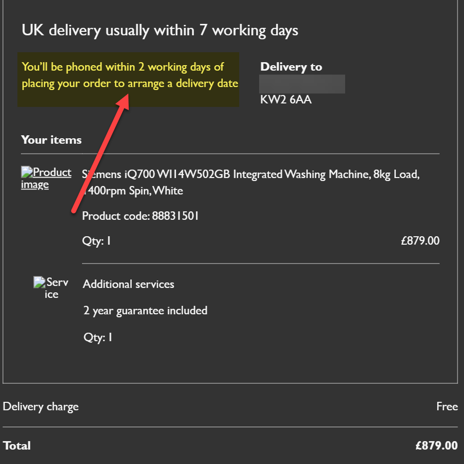
During order and checkout, I was told that the item would be delivered _usually_ withing 7 working days. Of course, the word “ususally” usually leaves room for variance and interpretation. And I got a “free delivery” and assurance they would call me within 2 working days after the order to arrange a delivery date. No “usually” there.
Order confirmation email from John Lewis & Partners
So, what happened next? I never got the promised call, but after a couple of days, actually after 7 working days, I received another mail telling me the item had been dispatched. So, no arrangement of a delivery date.
Item dispatch notice after 7 working days
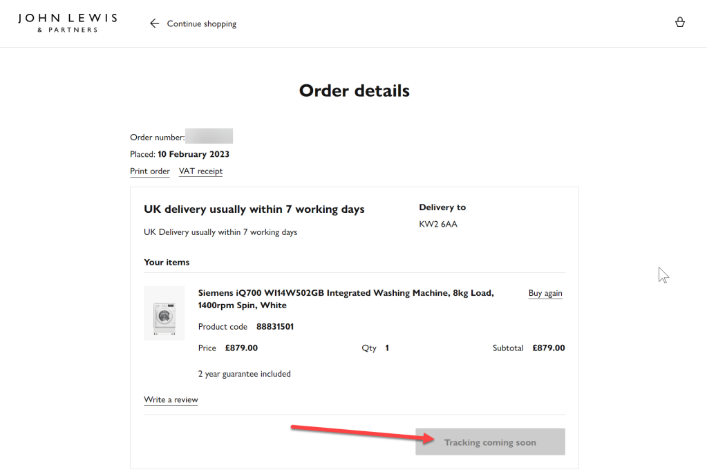
So, I waited another 24 hours as noted in the email to get the tracking link, so I could see in advance when the item was supposed to arrive. No luck that. Every day I checked the link, it only said “Tracking coming soon”.
John Lewis order details and no tracking link
Surprisingly, today I got a phone call from a delivery guy, telling me he was about to deliver an appliance. Unfortunately, I just left the property for some other tasks.
Now, less than 2h later and 10 working days after my order, my neighbour received the washing machine for me – with the tracking information still “coming soon” and me having to move the machine later on to my plot.
I would have thought that online retailers in 2023 could do better. – Hmm wait, I actually know online retailers that do better (for years).
Any “Customer Happiness Engineers” at John Lewis & Partners reading this?
And this is the end of today’s story about the delivery of a washing machine in the Highlands.
With the next Toyota Hiace and the Saurer 2DM around the corner waiting to be converted, I thought it was time for consolidating our vehicular electrical installations.
But before going into details, some history first: In 2019, we started on the VW Calkifornia T6 with a Super B Epsilon 12V90Ah LiFePO4 battery as a simple drop-in replacement and added a Votronic SMI 1200 ST inverter to it. And this was probably where I made my first two mistakes. At that time, I decided for Votronic and against Victron Energy. And I did not pay attention to the non-existing programmability and extensibility features of the Votronic inverter.
Once with a vendor stick with that vendor? There a pros and cons to it as we will later see.
When we later prepared our Hilux for our first longer trip to Loch Watenan, I opted for a Liontron 12V200Ah battery again (for the reason Liontron being way cheaper than Super B). And for the inverter/charger, I went for Votronic again (SMI 1200 and the same DC-DC charger 1212-45) .
But when I tried to get the DC-DC charger working, I realised that the D+ signal was not available on the Hilux. All in all, I did not get it to work in any configuration and looked for alternatives – which came in the form of the Victron Orion-Tr Smart DC-DC Charger family. And when I had to add an AC charger (where in the Hymer I could use the existing AC charger) to load the Liontron battery “on-shore”, I chose the Victron Blue Smart IP22 Charger.
So, at that time there was some kind of tie between Victron and Votronic. And the setup was getting more complicated and more complicated. And I am not only talking about the diminishing space in the trunk of the Hilux.
If I had known about the Victron MultiPlus series at that time I could have saved me a lot of headaches and complications.
It was shortly after our first and very successful trip to Loch Watenan, when we got rid of the Hymer and I added the battery from it as a second battery to the Hilux. And I got 2 more Victron DC-DC chargers. But I sticked to my Votronic inverter. And this is how the final layout looked like:
Toyota Hilux setup with 2 Liontron 12V 200Ah batteries, 4 DC-DC 30A chargers
This all worked well end of 2021 when one of the Liontron batteries did not want to charge properly anymore. The combined cell voltage stayed low at 13.1V with no single cell near at 3.5V and the internal BMS still reported 100% SOC.
So it was time for a change. And while doing that eliminting some design shortcomings of the current installation:
Invertert has a power maximum of 1200W.
AC charging is limited 30A.
Both 200Ah batteries are operating separated with one of them feeding the inverter and the other feeding the 12V DC sources.
Each pair of DC-DC chargers is bound to a single battery.
The alternator cannot feed all 4 DC-DC but only 3 chargers at the same time.
Have both batteries run in parallel to feed the inverter and the DC sources at the same time and thus reducing the maximum current at 1300W to 65A (when both batteries are dropping down to the minimu of 4* 2.5V = 10V) or considerably lower when running at 14V (45A) .
But the “best” of it, I then got rid of all the Votronic devices and can integrate and configure more easily with Victron. And I can do the same in the Saurer and HiAce.
I hope I can start with the conversion mid of March and will post updates on the way.
So, what do you think? (And no, I have no affiliation with Victron at all.)
The Caravan we got last year did not come with an inverter, so getting coffee in the morning or running a microwave was only possible when our main generator was running. And the installed battery for 12V support had a rather small capacity. This was clear to us from the beginning, as we eventually wanted to connect the Caravan to our EVE 280Ah cells.
But since we got our Starlink internet and our router did not seem to run easily on DC power, we needed -in addition to the temporary morning AC coffee spike – a more permanent AC solution.
Of course, first I updated the firmware of the inverter and configured it work with the battery:
Setting the AC input to 16A
Setting the battery type to LiFePO4
Setting the charge current to 70A (which is over the recommend amount of 50A, but see below for details)
As I did not want to connect a Cerbo GX to the system, I just used the VictronConnect App. Maybe I add a VE.Bus Smart dongle later on, or I connect some GX nevertheless. Who knows … Until now, it needs a wired connection to the inverter to see its status.
After powering on the generator, I confirmed everything was roughly working as expected. During the first run, the SOC was shown as 100% though the BMS of the battery internal saw it differently. In addition, the reported Amps and temperature were seen differently, as well. So, even that I set the inverter over the recommended maximum of 50A for the battery, the actual charge power was never much higher than the actual maximum).
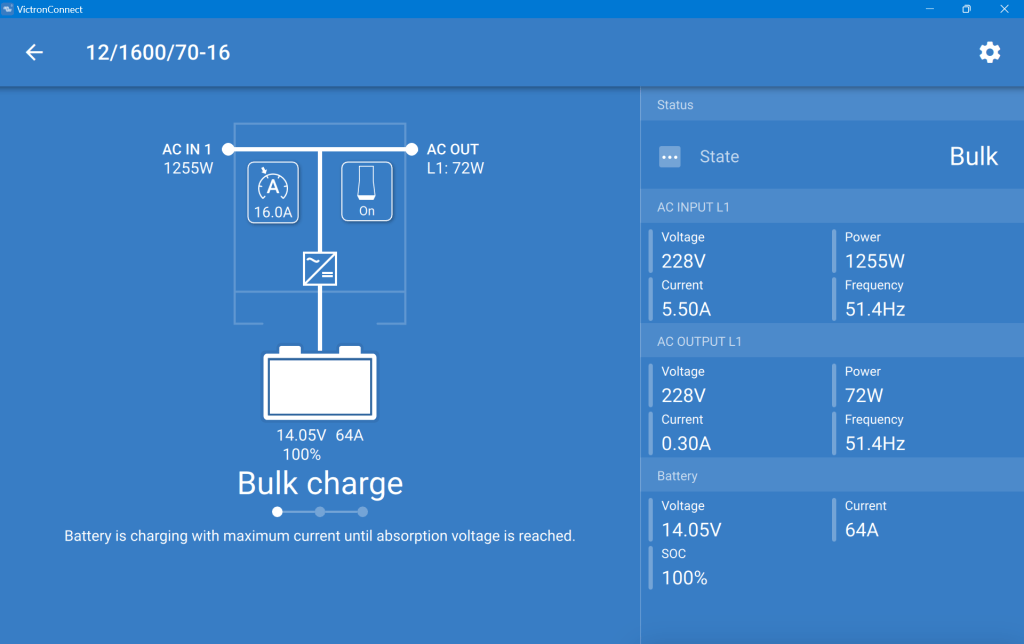
This is what the inverter saw (100% SOC, 14.05V DC cell voltage, charging at 64A):
MultiPlus charging the Liontron battery via the generator
And this is, what the Liontron BMS reported (76% SOC, 13.8V DC cell voltage, charging at 55.5A):
The SOC as seen by the Liontron battery BMS
In the end, the BMS stopped charging when it thought its batteries were full. And the inverter did not complain. However, I noticed that the cells were really not in balance (with a delta of 200mV between the lowest and highest voltage).
Discharging was ok, as well. However, I soon realised that the 100A discharge current could not be achived in my setup. The inverter tried to draw power and the BMS cut off with a “Discharge over-current” (OCD). SO, still no coffee via our Nespresso machine (and no microwave either, for that matter).
So, what is the take away of all this?
It works and now, I can run the Internet all day.
All in all, it is a relatively simple and quick setup.
The Liontron battery does somehow not live up to its specs (and yes, I know the battery could be a size bigger for what I want to achieve; but I did not want to buy an additional battery for this temporary solution).
It is way cheaper and more flexible than to buy this “off the shelf”.
Maybe, I add a Victron SmartShunt to get a more accurate SOC reporting (as I do not see any other way to integrate the BMS with the inverter).
Charging of the battery is quite fast when running the generator.
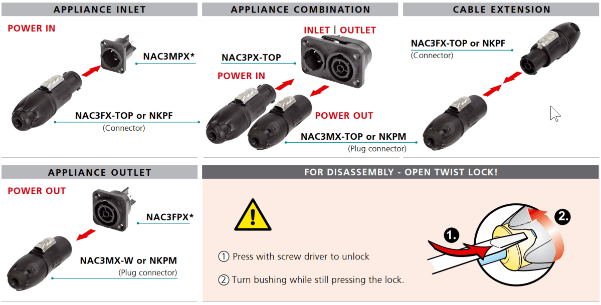
So, a few already know … In the last couple of days, I finally decided for a “universal” adapter standard to get rid of my UK, Swiss and European plugs and sockets. I looked at different adapters and the winner is:
The connector is a successor to the tried and tested “PowerCon” – but with some advantages:
It supports “hot-plugging” (connecting and disconnecting under load)
It is IP65 rated.
They come in a “L”-version for cables with a larger diameter. But even the normal sized connectors still fit a 3-core 2.5mm2 H07RN-F cable.
It is also a locking connector like the original PowerCon with male and female connectors and good for up to 16A. But they are a little more expensive. Interestingly, Thomann was the cheapest supplier I could find in Switzerland. Below you find a simple overview with the existing connectors and sockets along with their part numbers (taken from the Neutrik web site).
As you can see, there is no colour-coding for power inlets and outlets any more. Water-proof caps for the (wall) sockets are around 1.50 CHF per cap and therefore relatively expensive.
But what problem was I trying to solve in the first place?
We have AC electricity in our cars, the caravan and the trailers and soon in the barn and shed at the Loch. And we have appliances with UK, Swiss and EU (Schuko, Euro) plugs as well. And a plethora of adapters with the right one always not at hand. It was time to change that.
And the one thing I knew for sure was: I did not want to install UK sockets in the barn and shed. So, my idea was to install some more space-saving sockets. I already had good experience with the original PowerCon connector. However, they are not meant to be switched under load. Something that I definitely wanted to have with my new solution.
I could have sticked to plain Swiss connectors, as most of my appliances are already equipped with it. However, the typical Swiss triple T13 adapters tend to be occupied quite quickly as soon as we use AC/DC adapters or the Schuko fix-adapters. And if you get a quality product from a company like Feller, each triple socket costs around 50,00 CHF to 60,00 CHF. Compared to 3 Neutrik sockets this is way more expensive.
So, instead of researching any further, I quickly made a decision and went for the TRUE1 TOP system (from Liechtenstein). And it seems that I am not the only one with that idea, as I could see from various videos here, here, here and here.
My only real concern is, that after the “true” TRUE1 and the recent successor TRUE1 TOP, there will soon be an even “truer” replacement in the form of another imcompatible connector. But hey, what would one know anyway these days?
So, after last week the first batch of sockets and connectors arrived, this weekend I started with the conversion.
Inside our caravan, I added a couple of Neutrik sockets in the living room. See here:
Neutrik PowerCon True1 Top in our UK Swift Sprite Major 4 EB
I then updated the connections on the Toyota Hilux and relaced all the inputs, outputs and appliances. With this I could get rid of quite some adapters (from and to EU, UK, CH, CEE16-1, CEE16-3 etc).
Cooking with Neutrik PowerCon True1 Top in our Toyota Hilux
So what do I think so far? I am positively surprised.
Exchanging the connectors is simple and quick.
Even the thick 3-core 2.5mm2 H07RN-F cables fit in the connectors.
All the screws in the connectors are Torx (TX).
The connectors are not too bulky.
The adapters I made (e.g. from UK to Neutrik) are all rated for 16A (or 13A if we reuse the existing UK plugs). Travel adapters like the ones from Skross are typically only rated to 7A or 8A.
So, I will keep changing more and more of my appliances and will resurrect this post when I have news on this …