Hyundai HY1000Si as a cheaper replacement for the Honda EU10i

In one of our previous articles I wrote about the Honda EU10i as a backup generator for charging batteries via a Victron MultiPlus. Now as the supply chain has stabilised, the only noticable downside of this generator, that it will set you back a 1'000+ CHF (and even 1'000+ GBP in the UK). As we plan to equip our HiAce, Hilux, 2DM and possibly our trailer with such a generator this really adds up. So, I started looking for something cheaper – but hopefully equally robust, enduring and sturdy.

The requirements were basically unchanged. We want a generator that

  • is light
    less than 20kg including fuel
  • has a sustainable output of over 3.5A @230V
    as the MultiPlus-II 48/5000/70 has a minimum AC input limit of 3.5A
  • in combination with a MultiPlus 1600VA and PowerAssist must be able to provide more than 2'000W
    (which is already fulfilled when delivering more than 3.5A by itself)
  • generates more than 1'000Wh/l
  • must have an internal tank
  • generates more than 8'500Wh with the internal tank and an additional 5l tank
  • must be running petrol or diesel (the latter very unlikely in that weight range)
  • should be quiet
    the less noisy the better, no hard specs here
  • (optional) can be paired with another model to double the output
  • must have an automatic shutdown in case of oil issues and overload
  • must have an ECO mode
  • manual starter
    i.e. no battery needed for starting the generator
  • a seller with a service center from UK, CH or EU (preferrably DE/AT) for filing warranty claims if necessary

On AliExpress, eBay and Amazon there are quite some models for very little money. However, I also have very little trust (if there is such thing at all) in those product offerings.

So, when I did some modern research (i.e. googling around the internet) I came across three models:

  1. Hyundai HY1000Si (350 GBP)
  2. P1PE P1000i (300 GBP)
    formally known as Position One Power Equipment (kudos to the marketing department for such an intriguing brand name)
  3. Scheppach SG800 (200 EUR)

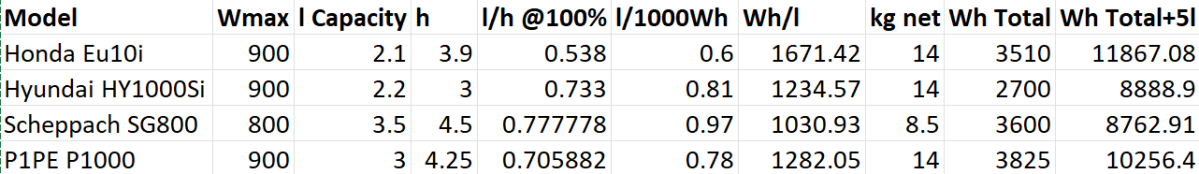
But before I go into detail here is a summary of the comparison:

Comparison of selected generators

Hyundai HY1000Si

This is the model I am most likely to buy (if I want to save money over buying the Honda EU10i).

Except for size, weight and price all its specs do not match the Honda EU10i (regardless of the slightly larger tank).

With a total advertised runtime of 3h it can produce 2'700W (which is the equivalent of roughly over a third of the nominal capacity of an 8s 280Ah battery – compared to nearly a half for the EU10i).

So unless we intend to use the generator only seldomly this would make a real (negative) difference in:

  • usability
    more frequent usage pattern, more refuelling operations
  • maintainability
    due to more service hours and material wear-off
    and efficiency
    longer runtime, more fuel consumption, more labour.

Compared to the Honda EU10i (which some consider the “gold standard”) there is relatively little information to be found about this generator (especially no thorough reviews).

Further note: From the advertised information the generator comes with some tools and replacement parts and even oil (which is an advantage over the Honda).

P1PE P1000i

Not a brand I have heard from before. It is a brand in the UK sold by the same company, GenPower Ltd, that is also the distributor for the Hyundai generators. And they heavily claim to use Hyundai engines as well. So much in fact, that at first sight it seems they *are* Hyundai generators.

The data sheet is to be questioned. A total runtime of 8.5h @50% load is advertised and no mentioning of any fuel consumption at 100% load. In the data sheet a fuel consumption of 550g/kWh is mentioned. With a specific weight of 740g/l for petrol this would equate to 0.74l/kWh which is not in line with the previous statement of 8.5h of runtime at 450W which would result in 0.78l/kWh. This would only “add up” with an assumed specific weight of 700g/l. And with petrols like E7 or E10 the specific weight will more likely further increase as in reduce. Furthermore, a generator running at 100% load is not expected to be as efficient as if it was running at 50% load. I am not saying that the 40ml/h make so much of a difference (it is slightly 5% off). I just get curious when the technical data sheet more looks like a marketing brochure. So, I would rather estimate a runtime of 4h at full load which would result in 0.83l/kWh or 1204Wh/l.

As P1PE seems to use the same Hyundai engines their increased efficiency over the HY1000Si would have to be in the “inverter” or electronics part of the generator. I do not find it likely that the cheaper model would have more efficient ingredients than the Hyundai model.

Scheppach SG800

A brand I have not heard from before either. Efficiency is not its strength and as I did not find it anywhere stocked, I merely list it here as an interesting option because of its form factor.

With only 800W this generator seems to be on the weaker end. But with only 8.5kg and a 3l tank it makes it up for its lack of efficiency and output capacity.

This might be an option where one really only rarely uses the generator. And then only to charge a battery (which is exactly what we aim for).

The price is debatable as I could not find it anywhere ready for order.

Summary

The choice for these small generators is rather small. If we were open for larger and heavier models the 2'000W range of inverters would provide a much broader selection (also with a higher price tag).

So, to come to a conclusion: it’s mainly price over efficiency and loudness. Is the spending of 2.5 times more justified for a generator which I only want to use in edge cases? For our use case, probably not.

WMF Lono Quadro mobile BBQ and the Victron MultiPlus Compact 24/1600/40-16

Though this could have been our first “unboxing blog post” in this article we only describe an already unboxed table grill.

Being able to have fires in the open less and less often it was time to find an electric BBQ alternative – with the constraint that it should run on a Victron MultiPlus Compact 24/1600/40-16 (or any other 1600VA sized inverter). After some frustration we finally found a nearly perfect match: the WMF Lono Quadro.

According to its spec sheet and product brochure, it uses 1250W – which is just under the nominal maximum power of 1280W that the MultiPlus can deliver.

Plus, the BBQ is relatively cheap. With a MRSP of 79.99 EUR it is available for as low as 60 EUR (PP included depending on your location). So, we ordered one of these table grills and gave it a try.

Upon powering up the device it uses its full power (regardless of the dial setting 1 .. 5) which results in a current draw of around 50A as seen on the BMS. The setting of the dial only seems to affect the intervals between heating (drawing current at 50A) and not heating (not drawing current at all).

The initial heating phase lasts naturally longer which results in the fan of the inverter kicking in at some point. But once the BBQ is at its operating temperature the fan is silent most of the time (as the heating intervals are relatively short). With 1250W nominal power consumption and a heat-up time of around 5min this consumes roughly 104Wh – about the same energy to boild 1.1l of water from 20°C.

During the use of the BBQ the inverter is pretty much at its power maximum and so has little to no resources left to power anything else. Though it seems possible to leave a fridge running, it might be better to unplug any consumers during cooking.

But all in all, with this table grill we now can do the BBQ inside (or outside) in our Toyota HiAce – even when we are on the move.

Some additional observations:

  • Weight
    The device is relatively heavy – especially the grill plate.
  • Size
    The usable size of the BBQ (270mm x 270mm) in relation to its overall dimensions seems quite large (while the whole device is still not bulky).
  • Power consumption
    Though the power consumption is rated at 1250W the heating intervals are relatively short which turn leads to a moderate overall power consumption.
  • Cleaning
    The grill plate can easily be removed and thus easily be removed (even in a dishwasher if you happen to have one in your car). Also, the drip tray can easily be removed and cleaned. Only the base plate is not meant for dishwashing.
  • Drip tray
    If the BBQ is not positioned horizontally (maybe due to the parking position of the vehicle) then the drip tray might have difficulties to catch all the fat that might float around the grill plate.

And this is it for today. Happy BBQing …

WMF Lono Quadro running from a Victron MultiPlus Compact 24/1600/40-16 at roughly 1250W/50A
Heat-up time is roughly 5min when turning the dial to the maximum position

Limiting the AC input of a Phoenix Smart Charger in parallel with a MultiPlus Compact

In a previous article I described the electric installation in our Toyota HiAce with a 24V battery and a Victron MultiPlus Compact 24/1600/40-16. At that point one piece was still missing: the Phoenix Smart IP43 Charger 24/25. It finally arrived this weekend and so it was time to install it; and configure it – which is normally not something worth going into lengthy detail.

However, in this case we wanted a kind of “special” setup which included the use of MultiPlus Assistants. So, in this article I will quickly describe what we wanted to achieve and how we implemented it.

In general, when connected to shore power we want to be able to limit the AC current drawn from the shore power. This is easily accomplished by setting a limit on the MultiPlus itself – or, as in our case, via the VE.Bus Smart Dongle. Though the Phoenix does have a VE.Direct interface and is able to be connected to a GX device, in our setup we did not want to use a GX device. So, essentially the Phoenix can only be controlled via Bluetooth and the VictronConnect app. But configuring the AC input limit on two devices (Phoenix and MultiPlus) is not only a nuisance from a usability standpoint, but also error-prone as one (or at least we) tend to forget things quickly. So, a different and better solution was needed.

Enter the MultiPlus Assistant in form of the Programmable Relay. With this, we can configure the built-in relay of the MultiPlus to open and close based on the availability of an AC input.

Note: we have to disable “Virtual Switch” in the MultiPlus to be able to use the MultiPlus Assistant.

The Phoenix has a Remote Input connector, that can be used to stop charging when the connection is “off”. So in our case, we enabled two Programmable Relay assistants:

  1. Programmable Relay, NC – On/Open
    After 5 seconds of AC input on the MultiPlus the relay is opened.
  2. Programmable Relay, NC – Off/Closed
    After 1 second of no AC input on the MultiPlus the relay is closed (which is the default state).

The wiring is as easy as to connect:

  • MultiPlus Relay COM < — > Phoenix Remote Input L
  • MultiPlus Relay NC < — > Phoenix Remote Input H

Note: on this page you find a description where the relay is located in the different MultiPlus models.

Below you find some screenshots with the configuration in VE Configure:

Disable Virtual Switch on MultiPlus
Add 2 Progammable Relay assistants
Programmable Relay ON after 5 seconds
Programmable Relay OFF after 1 second

So, five seconds after the MultiPlus has power via AC input it will open the relay which in turn will enable the Phoenix to start charging.

One second after AC input is gone the MultiPlus will close the relay so the Phoenix will stop charing (if it was charging at all).

The AC input of the Phoenix is connected to the AC output of the MultiPlus. So, when there is a AC input limit configured on the MultiPlus (such as 3A @230V) the MultiPlus and the Phoenix will not be able to charge with more than 3A. And from the MultiPlus perspective, the Phoenix is just an arbitrary consumer.

This can lead to some undesired behaviour if we were to limit the AC input to e.g. 1A. In this case, the MultiPlus would – when in Inverter mode – draw from the battery so the Phoenix could charge the battery. perpetuum mobile … ? And when the AC input is gone, this means that for roughly one second the Phoenix will also charge form the battery. But this is something I can live with easily.

And if we really had a very low power AC input (of e.g. 1A) we can still unplug the remote input and force the Phoenix not to charge. Or manually switch the MultiPlus to Charger mode only.

For us this is a usable solution without the need for multiple configuration changes nor the presence of a GX device.

Electric Installation in our Toyota HiAce 1994

Now, that we got our Toyota HiAce we thought it might be a good idea to add more power to the vehicle: in form of an 8s EVE LF280K LiFePO4 battery and a Victron MultiPlus Compact 24/1600/40-16 inverter/charger. In the following, we describe our setup and the reason why we built it like this.

The Requirements

  1. The sustained output power of the inverter must be over 1'200W.
  2. Charging via AC via EVSE or generator must be possible.
  3. Charging via alternator must be possible (but is not the norm).
  4. Charging of 60% of the battery (from 20% – 80%) via AC should take less than 180min.
  5. The installation should use the minimum amount of space possible.
  6. We should be able to use our existing Eve LF280K cells, thus limiting the overall current to 140A.
  7. As the vehicle will not have a diesel heater, it should be possible to run a 150W infrared heater for at least 3 * (4+2)h = 18h (^= 2'700Wh).
  8. In addition, the battery should be able to run a refrigerator with an average power consumption of 50W for at least 72h ^= 3'600Wh (next to other power consumption).

Design Considerations

  • With a maximum current of 140A and a cable run length of 1.5m, we should plan with a cross section of at least 35mm2.
  • Basically, with Eve LF280K cells we have three choices regarding the battery size:
    • 1* 4s (“12V”) Configuration
      4 * 3.2V * 280Ah = 3'584Wh
      This would lead to a required nominal AC charge power of at least 716.8W/h and a charge current of at least 56A/h.
    • 2* 4s (“12V”) Configuration
      2* 4 * 3.2V * 280Ah = 7'168Wh
      This would lead to a required nominal AC charge power of at least 1'433.6W/h and a charge current of at least 112A/h.
    • 1* 8s (“24V”) Configuration
      8 * 3.2V * 280Ah = 7'168Wh
      This would lead to a required nominal AC charge power of at least 1'433.6W/h and a charge current of at least 56A/h.
  • The Victron MultiPlus Compact xx/1600VA inverter/charger provides enough sustained power output (while being smaller than the non-Compact edition). Depending on the voltage of the battery, this will slightly impact the amount of charge current.
  • To charge the battery via the alternator we would need a DC/DC converter that depends on the battery configuration as well (either 12-12 or 12-24). So, let’s have a look at the battery first.

1* 4s (“12V”) Configuration

The smallest, lightest and cheapest configuration. But capacity requirements regarding the fridge are only fulfilled, if there are no other loads. In addition, the discharge current is relatively high (scratching the maximum discharge rate of 0.5C).

2* 4s (“12V”) Configuration

More complex setup, as each battery needs a separate BMS, which leads to the need of an aggregator for both batteries to correctly report SoC and calculate CCL and DCL. In addition, more cabling and fusing is required (and probably to a large bus bar). Comes with the advantage of having a redundant battery in case a single battery fails. Most expensive configuration.

1* 8s (“24V”) Configuration

Custom battery build needed, as there is not enough space for a typical 2 * 4 cells setup behind he seats. But, only a single BMS and thus less wiring is needed. Comes with a slight disadvantage of not having native 12V from the battery. This is actually not an isse, as all our DC devices also accept 24V. Cells can better balance voltage differences across a single 8s bank.

The Setup

In the end, I decided for the 8s configuration, due to less complexity. Splitting the 8s configuration across two cell blocks seemed to be an acceptable compromise.

As a regular MultiPlus 24/1600/40-16 would not fulfill my AC charge requirements, I had to decide to either add a second MultiPlus or to add a dedicated charger. I opted for a Phoenix Smart IP43 Charger 24/25 instead of a second MultiPlus. The MultiPlus in parallel would always consume 10W though most of the time I would not need the output power. Whereas, the Phoenix would only need power, when connected to AC. And reconfiguring the MultiPlus every time I charge was not an option for me. And yes, I lose redundancy – but also save some money (Phoenix is much cheaper). So, in the end the nominal charge power is 40A + 25A = 65A, which lets me charge at 1'560W reaching 60% within 165min.

The HiAce comes with a 70A alternator, so I chose a Orion-Tr Smart 12/24-15 DC-DC Charger. With this charger, I could run the engine in standby and still have the car heater running. And this is probably the predominant use case (if charging via alternator at all).

For the DC bus bar I went for a Victron Lynx Distributor, so I could use and install MEGA fuses. Having a 1’000A bus bar seems certainly overkill, but a separate bus bar and fuse box that accepts 35mm2 cable and MEGA fuses would be not be much smaller.

I changed the existing AC inlet of the HiAce to Neutrik PowerCON True1 TOP (congrats to the marketing department, I am still amazed how this name rolls of the tongue) and installed 2 Siemens compact 16A C RCBOs (external AC in, internal AC out). I am aware that theoretically I could support more than 16A on the internal AC out (via PowerAssist). If ever needed, I can replace the RCBO with a 20A version.

I added a VE.Bus Smart Dongle to the MultiPlus and opted against a complete (Raspberry-based) GX installation. The reason, I keep a USB MK3 with me anyway (in case I need to reconfigure the MultiPlus) and still have (Bluetooth) access to the most important settings and information of the MultiPlus. With the GX, I would to be running a WiFi hotspot (and consuming more energy as well). The disadvanage of not being able to use DVCC with information from the BMS is clear to me and accepted.

I selected a B2A8S20P JK-BMS that has an integrated 2A balancer and an RS485, CAN and heat port. In case, I ever add a GX device, I am still able to connect them and use DVCC.

The Specs

  • Nominal power (“capacity”)
    8 * 3.2V * 280Ah = 7'168Wh
  • Maximum discharge power 1’600VA (1'280W, capped by the inverter)
    with a maximum current of 80A/63A/55A (at 2.5V/3.2V/3.65V)
  • Maximum AC charge power 1'560W
  • AC Charging from 20% – 80% in 165min
  • Maximum DC charge power 360W
  • MultiPlus self-power consumption 10W

The Build

As mentioned before, due to space constraints I had to split the battery in 2 parts (with each having 4 cells). Instead of using utz RAKO boxes I used 12mm (sanded) plywood which I did not screw together but tied down with a banding/tensioning tool and a ratchet strap. With this setup, I can easily access und disassemble the cells if needed, while still having a sturdy case. Both cell blocks are connected with a (blue) Anderson SB175 connector.

The BMS itself is mounted to the side of one of the cases (I took extra care to use short screws, in order not to drill into the cell casing). I used M6 Weidmüller 35mm2 90° angled compression cable lug to get the wire away from the BMS and into the bus bar. All other compression cable lugs are DIN 46235 from Klauke (M6 35mm2 on the cells, and M8 16mm2/35mm2 on the bus bar).

The AC and DC wires are all Eland H07RN-F (except for the last two points):

  • Charger to bus bar, battery to bus bar: 35mm2
  • Cell block to cell block: 2 * 35mm2
  • Alternator to DC-DC converter, DC-DC converter to bus bar: 16mm2
  • External AC in to RCBO, RCBO to inverter/charger (both directions), RCBO to internal AC out: 3G2.5mm2
  • For the balancer cables on the cell blocks I used WAGO 221 inline splicing connectors with levers and bullet connectors with 2.5mm2 wire and M6 ring terminals.
  • For the connection of the Inverter/charger to the bus bar, I used the Victron installed 25mm2 welding cables.

Images

The installation is barely visible behind the seats
View from the back with preliminary wiring
Connection of cell blocks with SB175 connectors, cell block 2 and DC-DC converter
Lynx Distributor with cell block 1
Inverter/charger with space for second charger and cell block 2 (left)

Note: the Phoenix charger is not visible on the images, as I am still waiting for it to be delivered.

Charging via EVSE

Conclusion

We now have more than 7'000Wh of additional energy without losing any storage space for roughly 2'850 CHF/2’500 GBP (parts without labour). We can survive an extended weekend of 72h without recharging while still being able to enjoy amenities as using a coffee machine, heating and refrigerator. In case of longer periods of usage, we can recharge at any EVSE, or via shore power. And in emergencies, we can also charge via our Honda EU10i or via the alternator of the vehicle.

The battery is placed directly over the engine which helps in cold weather conditions to easily warm up the batteries to a chargeable level.

The installation can be monitored via Bluetooth (Victron Connect and JK-BMS app).

ESP32 with PlatformIO, C++, Unity and ESPIDF

As a follow up to my post about ESP32 with PlatformIO and Arduino, in this post I present how to use PlatformIO with the Espressif IDF (or ESPIDF, for short) in conjunction with C++ and Unity as a UnitTesting framework.

It proved to be much more difficult to get this running than with the Arduino framework.

Here are our requirements for development:

  1. Support (hardware and framework independent) unit tests to be run on the local dev machine (aka env:native).
  2. Support hardware and framework specific unit tests to be run on the actual microcontroller.

Here are some similarities and differences between ESPIDF and Arduino:

  • Again, the native environment will be compiled via SYS2/Mingw64 whereas the microcontroller environments are compiled by the compilers provided by the PlatformIO toolchain.
  • ESPIDF uses app_main() instead of the setup()/loop() construct in Arduino.
  • ESPIDF by default creates a main.c instead of a main.cpp file. We therefore have to use extern "C" { } to unmangle the symbols in our code.
  • For whatever reason the use of #ifdef __cpluscplus always evaluated to false and was therefore not usable. Thus, I used extern "C" unconditionally in the code.
  • To detect the ESPIDF framework, I used the ESP_PLATFORM symbol (instead of the ARDUINO symbol).
  • All framework dependent cpp and h lib files are guarded with #if defined(ESP_PLATFORM).
  • All test code (test_embedded and test_native) has to be surrounded with extern "C" as well (only the code and certinaly not the #includes).
  • Classes and code in lib_dir should not be surrounded with extern "C".
  • Also, I pretty much moved all the code to lib_dir, so the main.cpp is essentially only a stub.
  • We have to manually enable exceptions to support throw etc via build_flags: -fexceptions.
  • (not unit test related) Reading out GPIO to get the state of an LED always returns 0.

The final result can be found here.

Summary

Again, it is quite quirky to setup the development environment. Plus, I could not find a single example out in the wild (PlatformIO in conjunction with C++, Unity with embedded and native testing, ESPIDF).

In the end, I now have a working environment where I can hopefully do what I want to do: sending and receiving CAN messages via the TWAI interface. We will find out …

Reverse engineering the BYD Battery-Box Premium LVS CAN Protocol for Victron Venus OS

On my goal, to build a battery with a Venus OS compatible CAN interface I decided to have a look at he BYD CAN protocol – for several reasons:

  1. It is supported with Victron and Venus OS.
  2. I happen to have a BYD Battery-Box Premium LVS dual battery system.
  3. I heard mixed information about the Pylontech CAN protocol implementation.

So, I got myself a Kvaeser Memorator Light, in order to be able to sniff the CAN traffic between a Venus OS and the BYD BMS. For whatever reason, I did not get it to work, so I ended up with candump – which proved to be more that sufficient for what I needed.

Note: of course, before I started reverse engineering the protocol, I made some effort to find resources and someone who might have already done that – but no luck. However, there were some fragments regarding HVS systems. But they did not seem to be compatible with the LVS implementation.

If you are interested in the result, you can head right here. Otherwise, stay with me and I explain my approach to correlate the identifiers and data pieces.

  1. First, I just started candump to check the general message flow and to see some recurring patterns (working/normal operation, UseCase A).
  2. I then verified that the communication (which runs at 500kb/s) only consists of 11bit identifiers and no FD frames.
  3. I then identified the several message ids based on sender (TX, Venus OS) and receiver (RX, BYD).
  4. I then monitored the message flow, when I disconnected the BYB BMS temporarily (UseCase B).
  5. And then I monitored the message flow, when there was no BYD BMS present at start and then powered it on (UseCase C).
  6. Have alarms and warnings being sent by the BYD BMS (UseCase D). (see note below)

Things to consider:

  1. What are the units of the data being sent (e.g. temperature came in Kelvin/K)?
  2. What is the byte ordering (e.g for WORDs expect the low byte first and then the high byte)?
  3. Is there a scaling on the data being sent (e.g. 1/10mV)?
  4. Is information distributed over different messages? Or does one message have a special meaning in correlation to another message? (e.g. cell voltage and temperature)

For most of the parts, I *knew* what data to expect or to look for. I just looked at the BMS device inside the Venus OS and looked for data that matched the information shown on the GUI.

In the end, I identified most of the messages. For alarms and events, I will verify them once I have a working prototype on my ESP32 by simulating and sending them to Venus OS. [Edit: Alarms and Warnings are now identified and described. Events seem to be not supported. With 17 frames/messages I can now setup a complete BYD battery simulation towards a Venus OS.]

Here is a Summary: BYD Battery-Box Premium LVS CAN Protocol. There you find also some image of Venus OS with the correspnding information as shown on the GUI.

Hope you find this useful.

ESP32 with PlatformIO, C++, Unity and Arduino

After a quick adventure with the .NET nanoFramework on microcontrollers, I sort of came back to my senses and continued with something that seemed to have a brighter future (read: more supported boards, more documentation, bigger community, …). So, after a quick look around, I tried: PlatformIO:

Sounds just too promising. At least promising enough to reactivate my C++03 knowledge and bring it up to at least C++17 (spoiler: after all there _was_ a reason why I switched to C#).

On the way I found out, that we now support auto, bool and lambda expressions but kept the splitting-of-declaration-and-implementation-nightmare – yikes …

Installation

Installation of PlatformIO was really straightforward. After the installation of VSCode, I installed the Python, C/C++ and the C++ extension beforehand. That automatically brought me CMake as well. And after that I just had to add the PlatformIO extension.

From there I could start and create my first project. And depending on the framework chosen (Arduino in my case) the main.cpp comes with either setup() and loop() or just app_main() (EspIdf).

Note: if the main file (under the src folder) is a main.c we have to rename it to main.cpp to use C++ features – I totally forgot about that …

Unit Testing

Building and flashing the controller “just worked”. So, I started to port my C# HelloWorld morse code generator to C++. Certainly, I wanted to write some unit tests along that way. And there the “trouble” started …

There is documentation, but I totally missed the way how unit testing are to be done with PlatformIO (at least when it is one with Unity:

  • First, unit tests are either “local” or “native” tests (on your dev machine) or “embedded” tests. We have to set up a separate *environment* for each.
  • The microcontroller framework (Arduino, in my case) is not supported on the native environment (not even an #include <Arduino.h> is allowed). So, we have to make sure, we use only code that is totally hardware independeent.
  • PlatformIO does not install a toolchain for the native environment (i.e. we have to install a C/C++ compiler ourselves). And on Windows, it is recommended to use MSYS2 with Mingw64. That effectively means, we have different compilers depending on the environment. Something, that just feels weird to me. And something that could cause problems, as I later should find out.
  • Every test is compiled as a separate executable with a main() function. Something I am not used to in a .NET environment. And here is again, it matters which framework (Arduino or EspIdf) we are using, as we have to repeat setup()/loop() or app_main() again and again.
  • The main code in the src folder is compiled as well, which leaves us with duplicate main() function. Preprocessor with #if defined() to the rescue – quite clumsy …
  • And then the main thing: we essentially have to move all the application code to the lib folder, as -by default- the src code is not included when unit testing. That is not only strange to me, but leaves the src folder being an empty stub, as all the code now lives in the the (private) lib folder.
  • Documentation or the Calculator example were only partially helpful. I ended up with the weirdest compilation and linker errors I never dared to imagine.
  • Unity requires we need to specify all tests manually if we want to run them.

But in the end, I got it working. Here is what I did:

Summary

My first impression is … mixed. On the one hand, PlatformIO makes it relatively easy to develop for different hardware/boards. Due to VSCode the “developer experience” is much better than with the Arduino IDE.

But … setting up Unit Testing and how it is implemented is rather awkward. Needless to say, that error messages are not for the faint of the heart.

I cannot say, that I miss my C++ days. On the other hand, not something I could not get used to and around with it.

Hello, world! morse code generator on an ESP32

C# .Net on a Raspberry Pi 400 running Venus OS

Today, I tried to run a C# console application on a Venus OS – and it pretty much worked right away. But why would I want to do that?

The answer is simple: a couple of weeks ago I started to add some “drivers” to Venus OS to support additional features like using a MultiPlus-II as a charger for top balancing cells. With Venus OS, most of the examples I found were written in Python (except for some C++ extensions). And it is no secret that I am not too fond of that. So, why not using my favourite programming language on Venus OS as well?

My first thought was, I would have to install the .Net framework on Venus OS. But, with the advent of self-contained (and thus framework-independent) executables this is not needed.

First, I installed .NET on a Raspberry Pi 400 with Raspbian (just for the fun of it). I basically followed Deploy .NET apps on ARM single-board computers:

curl -sSL https://dot.net/v1/dotnet-install.sh | bash /dev/stdin --channel STS

echo 'export DOTNET_ROOT=$HOME/.dotnet' >> ~/.bashrc
echo 'export PATH=$PATH:$HOME/.dotnet' >> ~/.bashrc
source ~/.bashrc

dotnet --version

… and there it is!

And then it was time for another infamous Hello, world!:

dotnet new console -o HelloWorld
cd HelloWorld

And now for the compilation.

dotnet publish --sc -r linux-arm -c Release -p:PublishTrimmed=true

linux-arm was needed, as Venus OS is a 32-bit operating system (regardless of the 64bit architecture of the Pi 400). I chose PublishTrimmed to save some space. And of cource, --sc for self-contained.

I then gzipped the publish folder and copied it to the Venus OS (via WinSCP). After uncompressing the files (with permissions left intact), I ran the program and got this error:

Process terminated. Couldn't find a valid ICU package installed on the system. Please install libicu (or icu-libs) using your package manager and try again. Alternatively you can set the configuration flag System.Globalization.Invariant to true if you want to run with no globalization support. Please see https://aka.ms/dotnet-missing-libicu for more information.

Enabling invariant mode seemed to be the easier choice. After all, my future drivers would hopefully not need globalisation support anyway. So, I recompiled after adjusting the .csproj file:

<PropertyGroup>
    <InvariantGlobalization>true</InvariantGlobalization>
</PropertyGroup>

… and it worked:

root@raspberrypi4:~# publish/HelloWorld
Hello, World!

I executed this on a Raspberry Pi 400 running Venus OS v3.00 and .Net 7.

From there, I wanted to connect to D-Bus which proved to be more difficult. Following the Connecting .NET Core to D-Bus I had to find out that Tmds.DBus.Tool was not compatible with .Net 7. I will have to look into that separately.

Note about IL trimming: the size difference is really noticable. In my example the untrimmed compilation was around 65MB and the trimmed version around 13MB. However, it seemed to me that the trimmed version took slightly longer to load and execute. So, I am not sure if I will keep this switch on.

So, what would be the perceived advantages of using .Net on Venus OS for me?

  1. Known developing environment
  2. Better type safety
  3. Reusability of a lot of basic code
  4. Easier testing and mocking

But this is only my personal opinion and preference. Yours might differ.

Initial setup of a Venus OS on a Raspberry Pi without a wired network connection

When setting up a Raspberry Pi to run Venus OS, the GUI is not available on the local HDMI port – it is running headless by default. However, in order to connect to a Wireless network, we need to access that UI.

As mentioned in the above link, there is a workaround to it: renaming (or removing) the /etc/venus/headless file. This can be done by connecting via the serial port to the PI using the Adafruit USB to TTL serial cable. There is a very thorough article on how to connect to the port.

In short, pin 8 (GPIO14, TX) is white; pin 10 (GPIO15, RX) is green and pin 6 can be used as ground (black) and DO NOT USE the red wire. See here for the actual Pin layout. We can then use Putty to make a connection to the Pi (at 115200bps).

So far, so good. However, when trying to rename the headless file the following error message appears: mv: can't rename 'headless': Read-only file system

As pointed out in Cannot change headless – Read only filesystem on Rasp4 for Venus OS large two options exist:

  1. Make the file system read/write via /opt/victronenergy/swupdate-scripts/remount-rw.sh
  2. Enable superuser access (unfortunately, this requires GUI access – chicken-egg-problem here)

But instead of making the filesystem read-write until the next firmware update, I would rather only temporarily remount via mount -o remount,rw /.

And after that, renaming/removing the headless file succeeds.

Following the next reboot, the file system is then mounted read-only again and the GUI appears on the local HDMI port.

Now we can configure WLAN settings and everything else (such as superuser access) without the need for a wired network.

And in case you are in the need of a very small keyboard / display combination, you can use

Connecting to Wi-Fi with via Bluetooth and Victron Connect

In case you only want to connect to Wi-Fi and do not happen to have a serial cable, but you want to use the Raspberry Pi’s bluetooth connection, you can use Victron Connect to configure wireless network settings.

For this you start up Victron Connect on an Android (or Apple i device, Windows will nork work for that) and discover the Raspberry you want to connect. When pairing with the Pi use 000000 as the pin code.

After that you will find the gear icon in the upper right corner. From there you can select Network settings and connect to your WLAN.

Below you find some screenshots.

Bluetooth connection to Venus OS via Victron Connect
Configure Network settings
Connecting to a WLAN

Enabling WiFi on a Raspberry Pi 400 with Venus OS

When we run Venus OS without any modifications on a Raspberry Pi 400 no WiFi is detected – though the Pi 400 certainly has WiFi onboard.

As it seems, I am not the first one to notice that. bipedalprimate presented a solution by copying a bunch of Raspbian /lib/firmware files to the Venus OS. But as it turns out, things can be achieved much simpler.

It seems, that the driver on the 400 is differs from the chipset of a _regular_ Pi 4: it is the brcmfmac43456.

When looking at the /lib/firmware/brcm folder of a Venus OS these drivers are missing:

Venus OS v3.00 contents of /lib/firmware/brcm

On a Raspberry Pi 400 things look different:

Raspberry Pi 400 Raspbian 6.1.21 contents of /lib/firmware/brcm

As it seems, only a few files are required for a Raspberry Pi 400 and only a few belong to the brcmfmac43456. Most of the files are in fact links to other files (and some are in the cypress directory).

So, I did the following: I copied the brcm and cypress directories to a USB stick and inserted it into the Pi 400. From there I copied the driver files to the respective directories inside /lib/firmware, added some links and adjusted the permissions. Below you see the commands I used.

Note1: I am a novice when it comes to Linux, so pls do not expect any sophisticated shell scripting.

Note2: by default the root file system is _read-only_. Therefore I re-mounted it as read-write (so, maybe our changes will not survive a firmware update).

Note3: my USB stick was mounted as /run/media/sda1. Yours might be different.

mount -o remount,rw /
cd /lib/firmware/cypress
cp /run/media/sda1/cypress/cyfmac4356* .
chmod 644 cyfmac4356*
cd /lib/firmware/brcm
cp /run/media/sda1/brcm/brcmfmac4356-pcie.gpd-win-pocket.txt .
chmod 644 brcmfmac4356-pcie.gpd-win-pocket.txt
ln ../cypress/cyfmac4356-pcie.bin brcmfmac4356-pcie.bin
chmod 777 brcmfmac4356-pcie.bin
ln ../cypress/cyfmac4356-pcie.clm_blob brcmfmac4356-pcie.clm_blob
chmod 777 brcmfmac4356-pcie.clm_blob
ln ../cypress/cyfmac4356-sdio.bin brcmfmac4356-sdio.bin
chmod 777 brcmfmac4356-sdio.bin
ln ../cypress/cyfmac4356-sdio.clm_blob brcmfmac4356-sdio.clm_blob
chmod 777 brcmfmac4356-sdio.clm_blob
ln brcmfmac4356-sdio.AP6356S.txt brcmfmac4356-sdio.khadas,vim2.txt
chmod 777 brcmfmac4356-sdio.khadas,vim2.txt
ln brcmfmac4356-sdio.AP6356S.txt brcmfmac4356-sdio.vamrs,rock960.txt
chmod 777 brcmfmac4356-sdio.vamrs,rock960.txt
cp /run/media/sda1/brcm/brcmfmac43456-sdio.bin .
chmod 644 brcmfmac43456-sdio.bin
cp /run/media/sda1/brcm/brcmfmac43456-sdio.clm_blob .
chmod 644 brcmfmac43456-sdio.clm_blob
cp /run/media/sda1/brcm/brcmfmac43456-sdio.txt .
chmod 644 brcmfmac43456-sdio.txt
ln brcmfmac43456-sdio.bin brcmfmac43456-sdio.raspberrypi,400.bin
chmod 777 brcmfmac43456-sdio.raspberrypi,400.bin
ln brcmfmac43456-sdio.clm_blob brcmfmac43456-sdio.raspberrypi,400.clm_blob
chmod 777 brcmfmac43456-sdio.raspberrypi,400.clm_blob
ln brcmfmac43456-sdio.txt brcmfmac43456-sdio.raspberrypi,400.txt
chmod 777 brcmfmac43456-sdio.raspberrypi,400.txt
mount -o remount,ro /
Commands necessary to enable WLAN support on Raspberry Pi 400 for Venus OS v3.00

Two brcm-links are giving errors, but this can be ignored. The links on the Raspbian are not working either.

After copying the files both directories looked like this:

Venus OS v3.00 firmware brcm and cypress folder after adding the driver files

After a reboot I could browse and connect to my SSID via Settings, Wi-Fi:

Wi-Fi networks visible after a reboot
Established connection to a Wi-Fi network

And from the serial console, ifconfig also showed our new interface:

Venus OS recognising the Raspberry Pi 400 WiFi interface

Now, the Raspberry Pi 400 can be used like any other Pi with Venus OS.

Thanks again to bipedalprimate for pointing me in the right direction!