
As finally our wood arrived we could now complete the arch for our living room. With this in place, we can continue with the roof …


Current state of our electric installation
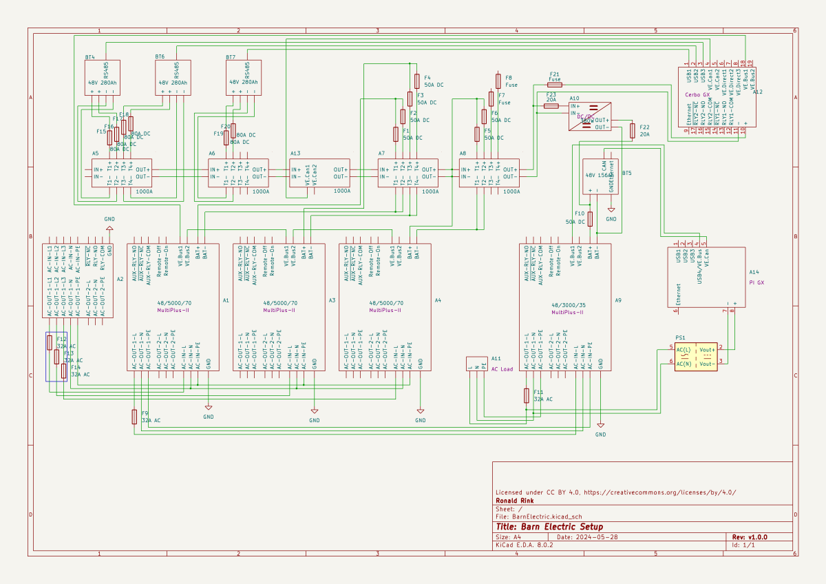
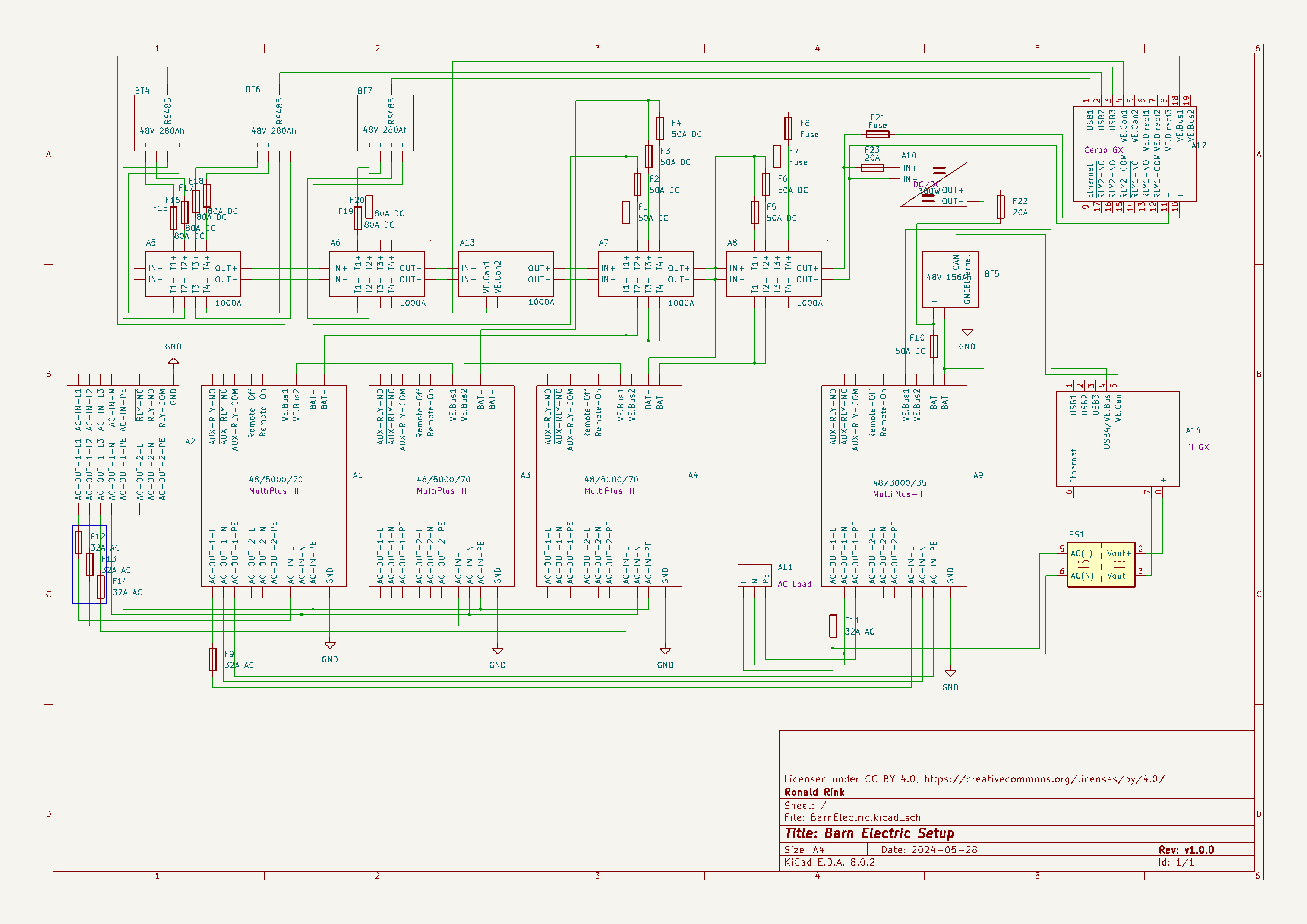
I recently wrote about our upcoming solar PV adventure. But before updating our system, I thought it was time to document and explain our current setup (with the help of KiCad).
This system is the main electricity for our barn and currently consists of three batteries with an energy (often referred to as “capacity”) of 3* 14.33kWh = 43kWh (battery bank A, A1:A2 on the plan). These batteries are charged by a JCB G20QS (B1) via three MultiPlus-II 48/5000/70 inverters/chargers (B1:C2) which are by default in “Charge Only” mode. The MultiPlus-II are configured in a 3-phase configuration but only turned on when 3-phase is actually needed.
The main power is delivered by a MultiPlus-II 48/3000/35 (B4:C5) that is connected to a separate battery bank (battery bank B, BYD LVS Premium Battery-Box with an energy of 8kWh). This latter MultiPlus-II is connected to L1 of the 3-phase MultiPlus-II. So, whenever the main batteries get charged the cascaded inverter will also be charged. In addition, we can then use PowerAssist to up to supply 8'000VA (= 5'000VA + 3'000VA) when running on batteries and up to 14'500VA (= 6'500VA + 5'000VA + 3000VA) on a single phase.
Though the generator can supply up 14'400W the chargers of the Multiplus-II can only charge with a power of up to 3* 48V* 70A = 10'080W. This is actually an advantage as the optimal efficiency factor of the generator is roughly at 12'000W. So with 210A we are pretty close. If we ever added more chargers to the system we could even slightly increase the charge current to 250A.
System A with the 3-phase inverter configuration is connected to a Lynx bus bar (A1:B4) that also includes a Lynx shunt (B3) used for measuring over all batteries. In addition, there is an islolated Orion-Tr DC-DC charger (A5) that constantly feeds system B.
System A and B are connected to their separate GX:
- system A
Cerbo GX, A5:A6
MultiPlus-II via VE.Bus, Lynx Shunt via VE.Can, JK-BMS via RS485/USB - system B
Raspberry Pi4 running VenusOS, B5:B6
MultiPlus-II via VE.Bus, BYD BMS via VE.Can (on a Pi GPIO Hat)
And this is it for the electricity installation in our barn.
Note: This cascaded setup is officially not supported by Victron, but it has been working for us without problems for months now. This might be different in your case.
Addendum
./.
Corrigendum
./.
About our new PV System
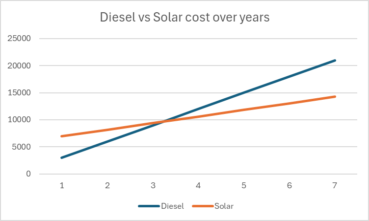
We finally did it and decided to get a PV system for our barn. Though we had been thinking about this since we started building on our plot, it never seemed to really pay off. A solar installation in very north of the Highlands?! But with prices for PV modules falling and falling I did another “business case” to see where this would land.
In the following figure you see the condensed outcome. In 38 months we would “break even” and roughly save over a 950 GBP per year over the course of seven years.
Selecting Modules for the Roof
But first, let me begin from the beginning … for the last two years our JCB G20QS backup generator has been sitting outside in the rain and collecting not dust but rust – that is why we decided to build a small shelter on the south end of our barn. Once we finished drawing the shelter with its 36m2 roof, we thought that a south-facing roof would be perfect for collecting solar energy in the summer. Remembering my last calculation, I knew that the slope of the panels for winter and summer time differed dramatically. That was when we started thinking to place additional modules vertically on the south wall of the barn.
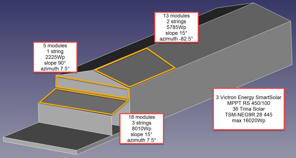
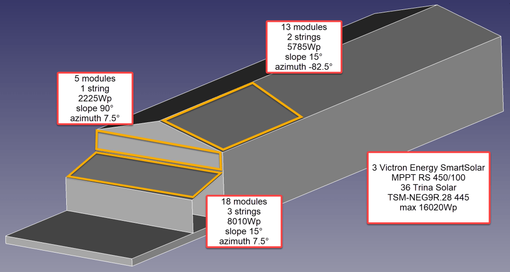
After we realised how much sheet metal for roofing would cost, we looked for for cheap solar modules that could be used as a cover for our shelter. We selected the Trina Solar TSM-NEG9R.28 445Wp module with dimensions of 1762mm x 1134mm x 30mm that would fit well as a roof.
Selecting MPPT Chargers
With the PV modules selected I had to choose between a AC-coupled and an DC-coupled system or a mix between the two. As our system is off-grid and I expected fast-changing workloads in our environment I decided for a completely DC-coupled system.
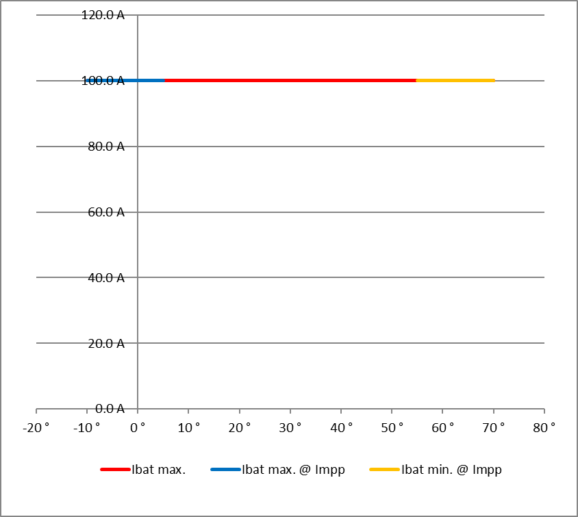
Already running a Victron system, I wanted to use Victron MPPT chargers for the installation. After checking and comparing the prices of different chargers (with a VE.Can or a VE.Direct connection), I started the Victron Energy MPPT Calculator and added my solar panels to it. I then did a couple of modifications to the spreadsheet (by prior removing the password and protection from the sheets) and found the Victron Energy SmartSolar RS 450/100 to be the best choice. With this charger I could fit 7 modules per string in order not to exceed Voc. The power would be limited by over 30A at minimum temperature but I do not expect much sun in the colder months anyway. At max temperature there would also be a cap by roughy 15A but I expect to have large amounts of excess energy during the sunnier months – so need to worry.


Note1: there seems to be a bug in the spreadsheet version BHO 01-2021 4.0 when using the “MPPT RS” tab. The calculation table uses the selected voltage in cell E15 from the “Blue- & SmartSolar” tab (and not 48V as the only possible voltage for the RS) and from there miscalculates the currents.
Note2: when selecting the number of modules and the diameter of the cabling, the up/down buttons do not seem to work correctly. Typing the values directly into D16, D33, K18, J35 and K35 works around this issue.
Module Placement
To get a better understanding where to place the modules and what difference it would make, I used Photovoltaic geographical information system (PVGIS) of the European Union (see also my earlier article More Power on how to use it).
After selecting the location of our barn I tried different combinations an panels with these constraints:
- slope of the existing barn is
15° - barn roof can fit a maximum of
28panels - azimuth of the barn is
7.5° - azimuth of the shelter is therefore also
7.5° - maximum slope of the shelter roof is
15°in order to maximise the number of vertical modules - shelter roof can fit a maximum of
18modules - south wall of the barn can fit a maximum of
5modules

Power Prediction
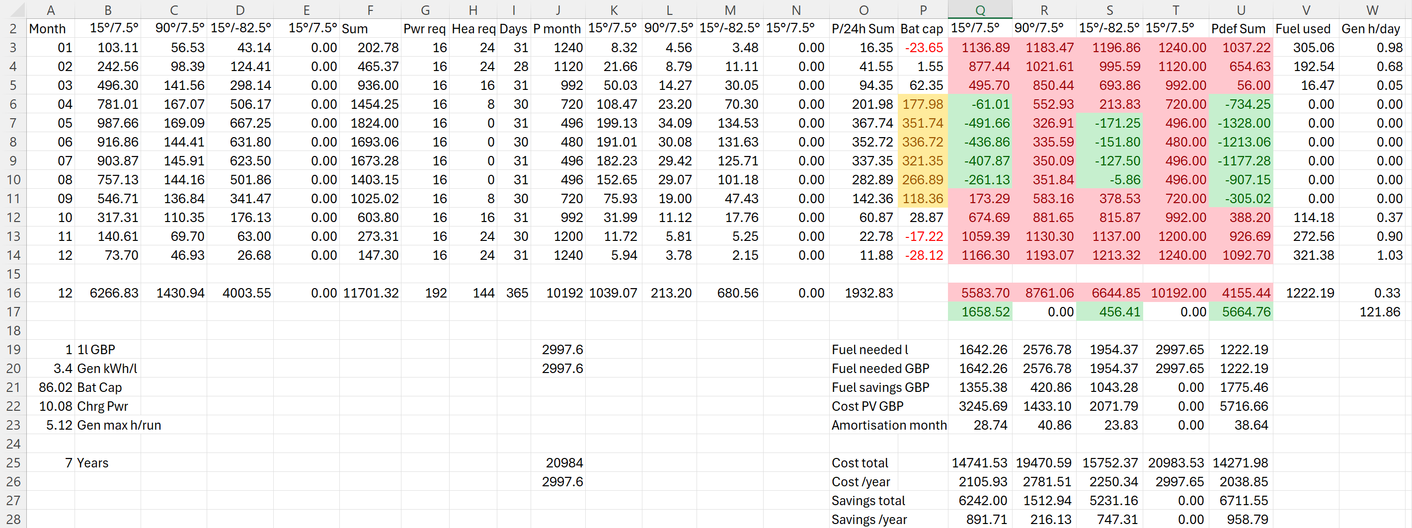
I then combined the info into a table to see if and how much energy could be produced. For this I estimated the amount of energy I would need in the forseeable future per month (electricity and heating) which varies between 480kWh and 1'240kWh.
Note: currently we do not need even 25% of that amount.
The numbers with red background reflect the energy deficit for that month. Numbers with green background show an excess power production for that month. The total of all panels is shown in column U. From there it is compared against our generator which would roughly need 0.3l/kWh (row 26).
So, for the first part of the installation I will add 36 modules on 6 strings as you can see from the image below.
Anticipating Change
It is interesting to see how a 25% increase of diesel cost changes the picture:
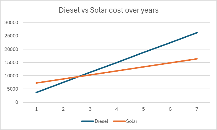
As we still have space for more modules on our east-facing barn roof, I could add another set of (larger) modules. And this would reduce fuel consumption by approx. 20% by deferring the “break even” to 55 months!

But it gets interesting when we take rising fuel cost into account.


With these additional modules we could run the whole winter with only one filling of our diesel tank and thus avoiding a costly refill during the winter season. So, this is something to be considered for the future.
Distributing Modules
Before wrapping it up, I will quickly motivate why I chose three SmartSolar RS 450/100 instead of one SmartSolar RS450/100 and one SmartSolar RS 450/200 and their connetion to the modules. With three instead of only two devices the average power reduction during a failure is only 33% instead of 50%. Power limiting is not such an issue, as the strings will be connected as follows:
- Charger 1
117.3 A min temp / 96.2A max temp
string 1: 5 modules 90°/7.5° south wall
string 2: 7 modules 15°/-82.5° east roof - Charger 2
117.6 A min temp / 96.4A max temp
string 1: 6 modules 15°/-82.5° east roof
string 2: 6 modules 15°/7.5° south roof - Charger 3
117.6 A min temp / 96.4A max temp
string 1: 6 modules 15°/7.5° south roof
string 2: 6 modules 15°/7.5° south roof
Conclusion
I certainly do not know how much energy will really be produced. But it is clear, that I will have excess power in the summer when I do not need it and not enough power in the winter when I need it.
Additionally, I merely save a 950 GBP per year – not taking into account:
- that I already have a required inverters, bus bars etc;
- any labour on my side to design and install the system;
- that the system gets more complex and error prone.
So, in reality I probably do not really save much to anything with this installation, as Diesel is still way too cheap. Though I certainly benefit from that, it is actually a shame. There should be more incentives for cleaner power generation.
As a side note: In case you missed why we went for a generator in the first place., here is why. The quote from the power company for a grid connection was way over 35’000 GBP. For this amount I can easily buy a generator, inverters, batteries and even solar modules.
And I already have an idea what to do with all the energy during the summer months that we really do not need: brewing a red ale with green energy …
Addendum
./.
Corrigendum
./.
Ground Floor completed
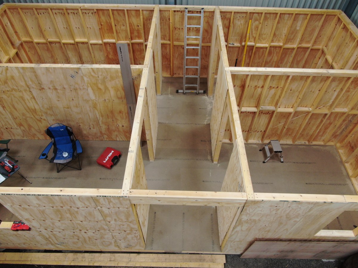
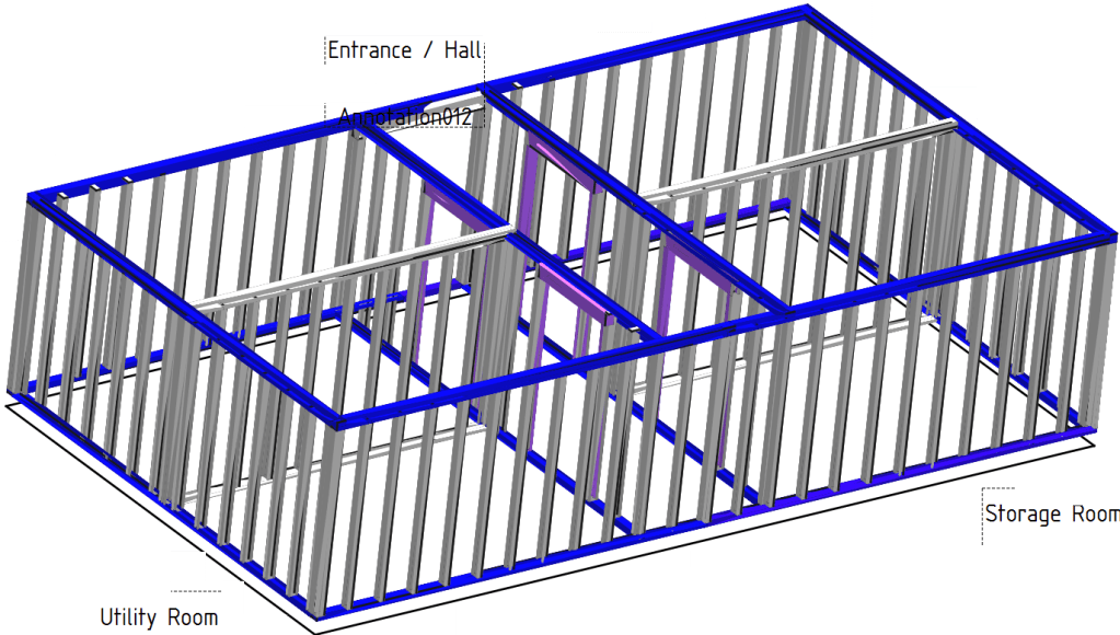
With Christmas on the missing doorsteps (pun intended) we now have completed the ground floor of our tiny-house-in-barn. See for yourself …
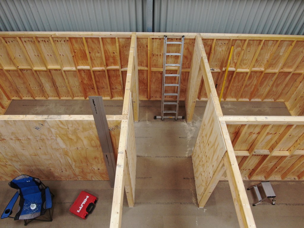

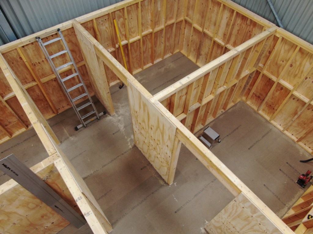

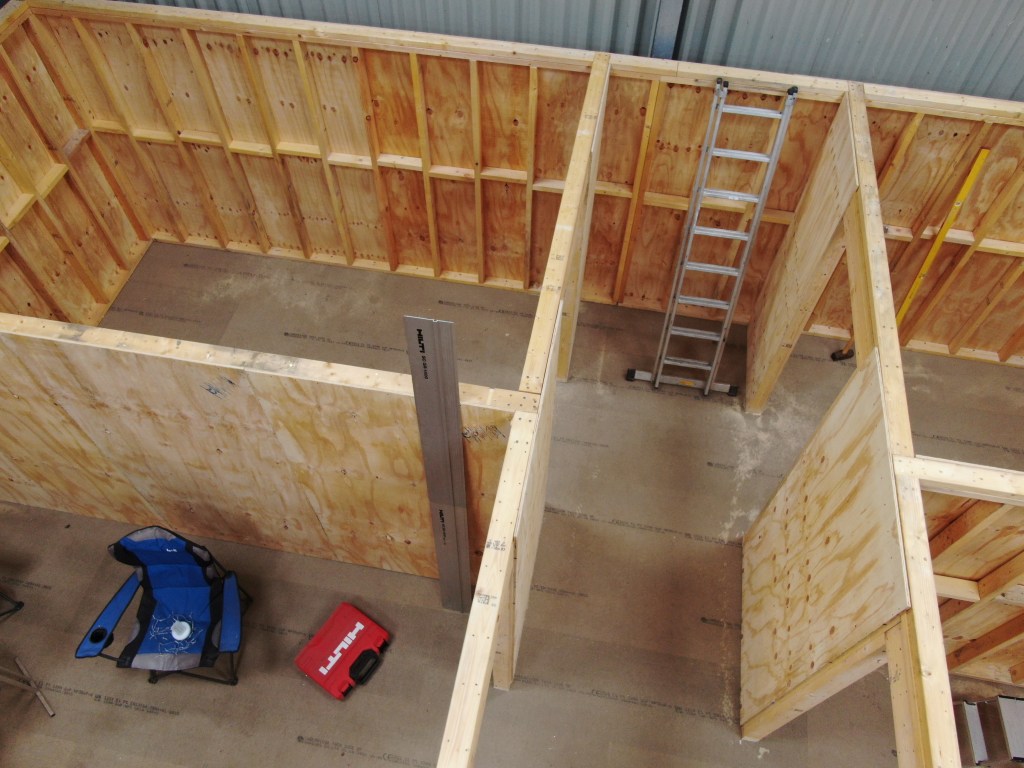
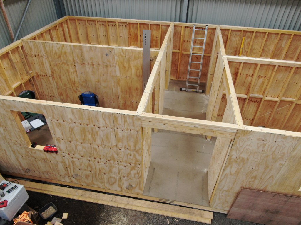
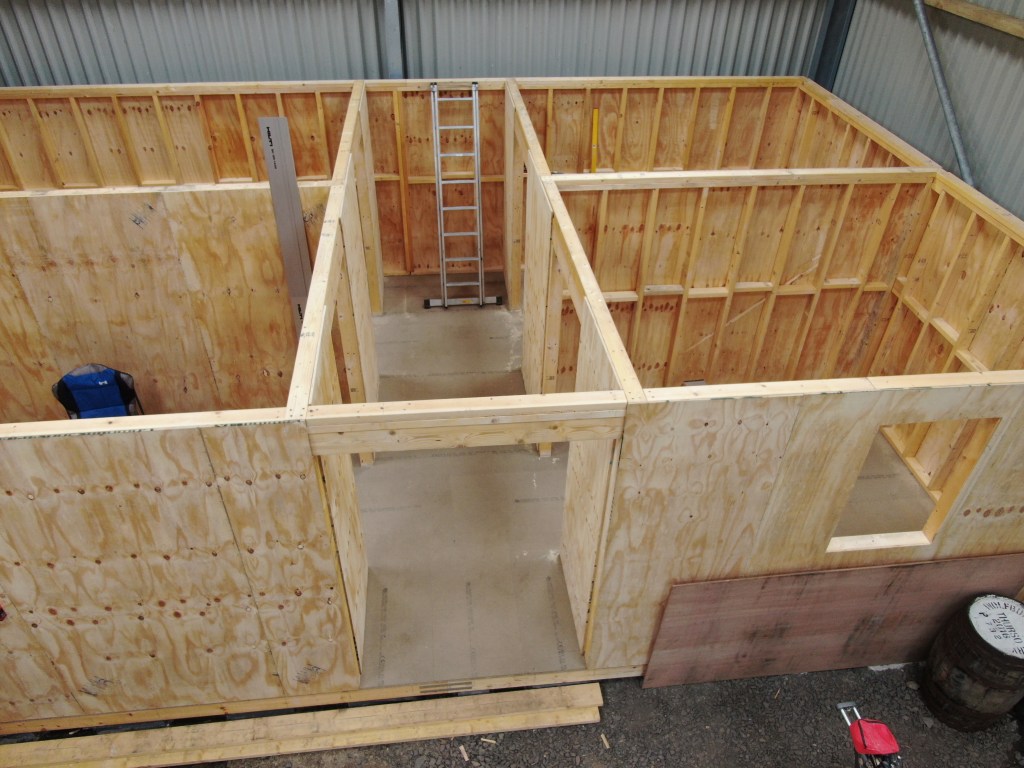

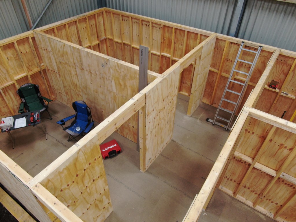
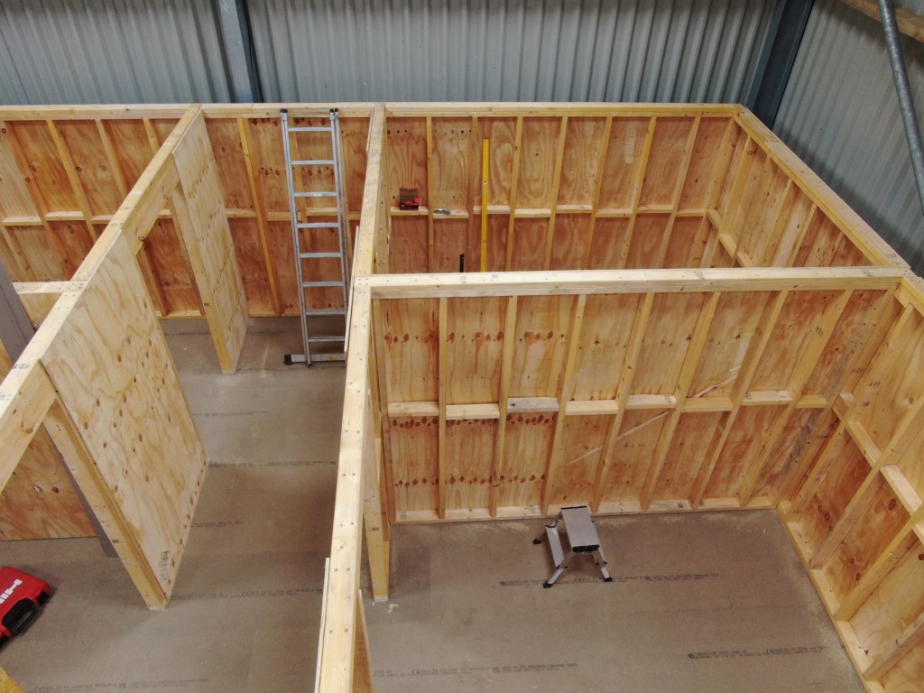
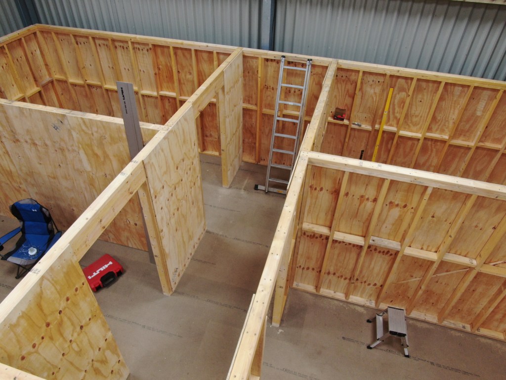

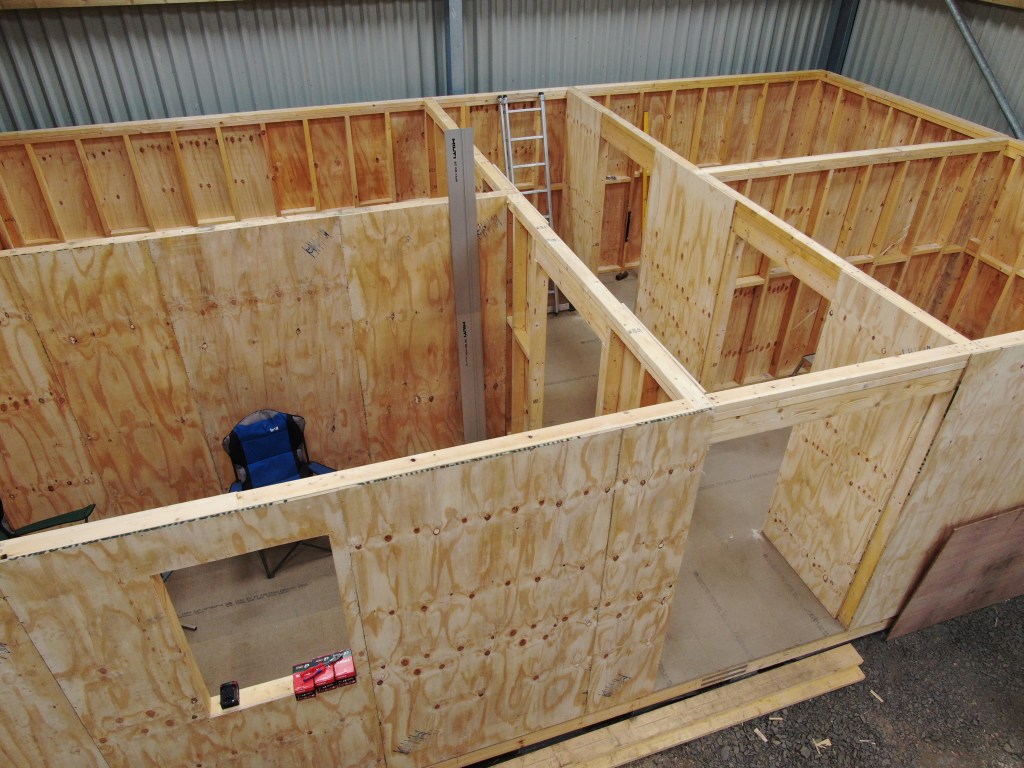
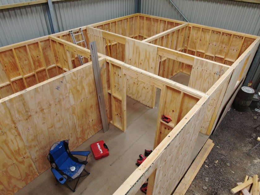
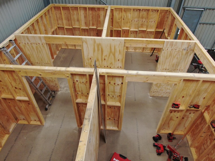
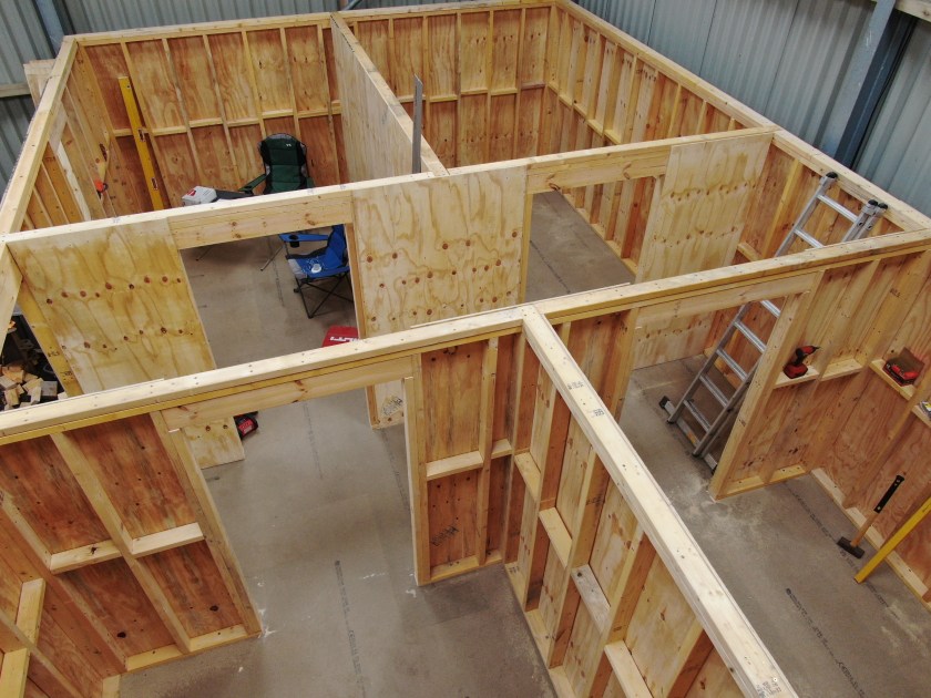
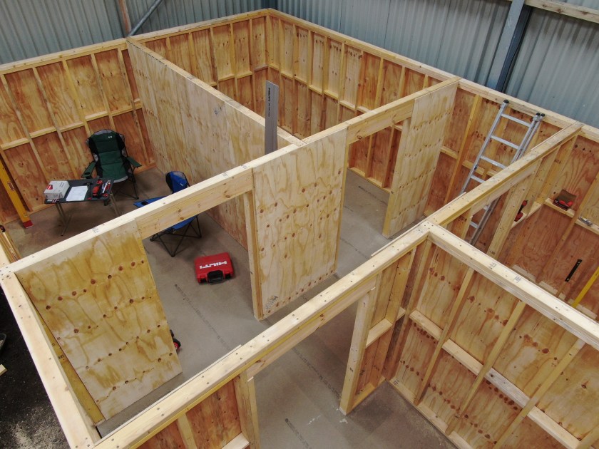

Here is a complete view of the shed-to-be from different perspectives.
Overview
Ground Floor
First Floor
A look into Siglent SDS2000X Plus Software Options
In this article, we have a look into the software options of the Siglent SDS2000X Plus digitial oscilloscope series.
The SDS2000X Plus series has been around for quite some time and – while still on sale – has been superseded by the Siglent SDS2000X HD series. It consists of a 2-channel entry model and three 4-channel models with varying bandwidth (100MHz, 200MHz, 350MHz). Interestingly the hardware in these models is exactly the same (with the one exception of the 2-channel model only having a single acquisition unit). For more details have a look at this video where the device is taken apart:
As mentioned in the video, there seems to be the possibilty to upgrade the bandwidth of the oscilloscope to up to 500MHz and additionally unlock a few other options. According to the manufacturer’s web site the value of the software options can add up quite considerably to a multiple of the actual oscilloscope:

The author of the video, which partially seems to divide its audience by its tonal pitch, remains cryptic about on how to actually do this but only refers to a post on this forum. So the question remains, is this really doable? and if yes, how does it work?
Note1: In case someone is wondering if it is allowed to generate software keys, an option might be to contact the manufacturer to get clarification on this subject.
Note2: I bought my scope with a couple of software options. So, no need for me to generate keys, I would not have otherwise.
The questions
According to the forum there seems to exist confusion about the following areas:
- What is the
SCOPEID?
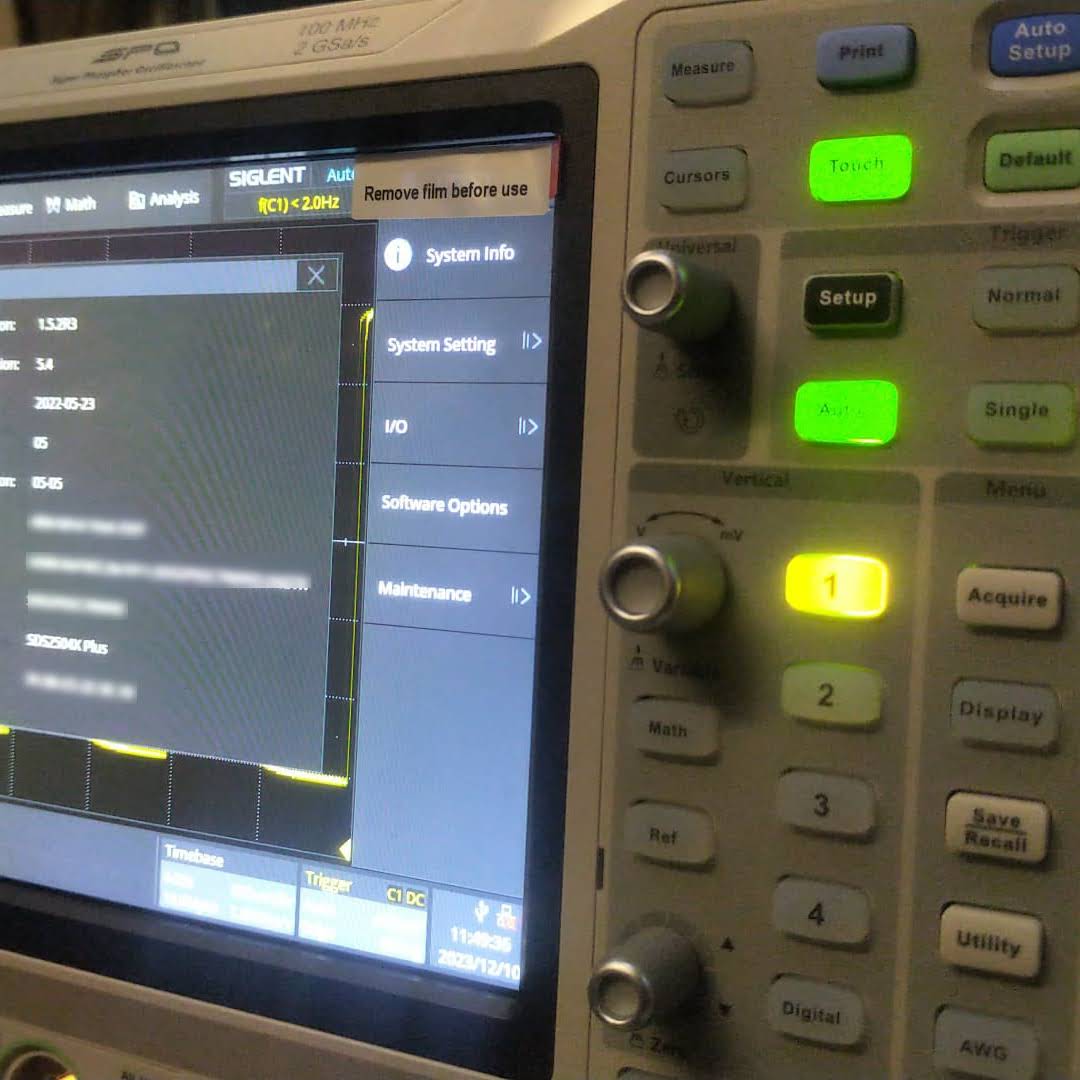
TheSCOPEIDis the 16-digit value you find when you open Utility, System Info and strip of the dash characters from “Scope ID“. - What is the
Model?
According to this video the model just stays as it is. So no replacing of the pre-defined value at all (regardless of the actual model we have). - Which firmware versions work with it? And do I have to downgrade first?
As it we can read from the Siglent SDS2000X Plus Release Notes, beginning withv1.3.9R10no downgrade can be done to any version older than that version. In the previously mentioned video we see that exactly that version is used for the demonstration. - Which keys (based on
bwopt) work for which option?
The script generates keys that do not necessarily match 1:1 to the options in the oscilloscope. But a look and search into the user manual reveals that the abbreviations in the script correspond to the product numbers. So for example,MSOis the abbreviation for the 16-channel logic analyser option. However, some keys generated by the script do not seem to have any corresponding sotware option at all (such asMAXorWIFI). - How to generate keys for options originally not included in the script (eg.
MANC,SENT)?
There are options present, especially theMANCHandSENToption, that are not being generted by the script at all. All one would have to do, is to addMANC(mind the missing ‘h‘) andSENTto the array ofbwoptand have to re-run the script. - Is there any order in applying the software option keys? Or anything else to consider?
Everytime a new key is entered, immediate feedback on the screen shows if a key was accepted as valid. A reboot seems to be required to activate the associated function. However, it is not problem at all to insert multiple keys or software options without rebooting.
A special note about the bandwidth option: as one can see from the web site, it is not possible to buy a500MHzlicense upgrade for aSDS2104X. Only the200MHzoption is available. After appliying an upgrade the actual model number of the oscilloscope changes as well and a new bandwidth option appears for that new model. So essentially, an upgrade on aSDS2104Xto a500MHzversion (SDS2504X) must be done via these intermediate steps:200MHz,350MHz,500MHz. In the end, only the label printed onto the oscilloscope shows its true origin.
An upgrade to a more recent version of the firmware afterwards is possible but optional.
Note1: after upgrading to500MHzthere is no more bandwidth option thus reducing the number of license options by one. I mention this, in case you thought something went missing.
Note2: the standard probes only work up to200MHzand also the high-end probe goes only up to350MHz. So, in order to be really able to use the full500MHzone probably has to get hold of an active probe.
The script
The script itself is pretty basic. The magic MD5 hashkey is being mangled with the Model and the SCOPEID. And then for each bwopt a new key is generated. Interestingly, the gen function never makes use of its parameter x and opt is implicitly referenced from the global scope.
The conclusion
Essentially, this has been a story about weak license keys. Though it might seem perfectly doable to generate keys for software options without reyling on the manufacturer, this is not something that can be generally recommended.
Custom flexible busbars versus pre-built busbars for LiFePO4 cells

Since we started building our own batteries we have been using custom busbars made of Klauke DIN 46235 M6 compression cable lugs and Eland 35mm2 H07RN-F copper wire cable. The initial reason for this having no busbars that really fitted the way we arranged the cells in our utz RAKO boxes (see here, here and here).
I never actually measured the difference in internal resistance of the ones we built and some we got with our EVE LF280K cells. Time to correct this …
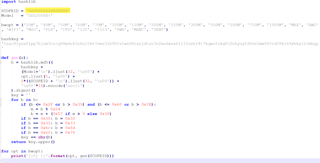
The flexible busbars delivered with our cells have approximately these dimensions: 105mm * 20mm * 2mm. This should give us a surface area of 40mm2 and an ideal internal resistance of around 0.045mOhm (according to some online calculators).
When measuring this with our trusty and highly precise TR1035+ the result displayed is 0.08mOhm.
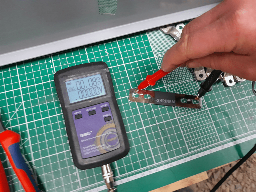
The Klauke version which comes with tinned copper lugs gives us a reading of 0.06mOhm – despite the smaller cross-section of 35mm2. The ideal internal resistance of the copper wire could be expected to be around 0.051mOhm (according to some other online calculator), so we are much closer to the measured value.
The display error of the TR1035+ is expected to be similar as the measured range of both busbars is quite similar. There is certainly quite an amount of uncertainty (not only due to the maximum resolution of 10uOhm) to it. But it is interesting to see that the resistance of the custom busbars seems to be lower despite its smaller cross-section – while being better insulated (not seen on the picture) and more flexible at the same time (as it can be bent in more directions).
Producing these custom busbars is certainly more expensive (a single lug costs around 1.17GBP or 1.27CHF) and involves more manual and time consuming labour. However, it is quite easy to double them and/or increase its cross-section to up to 70mm2 per wire (when using multi-stranded DIN EN 60228 conductors).
So, this is it for today with fascinating facts about busbars for LiFePO4 cells.
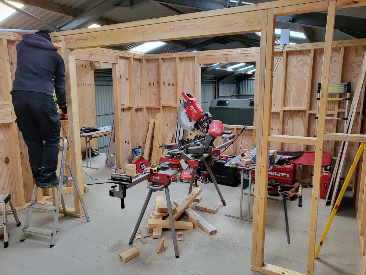
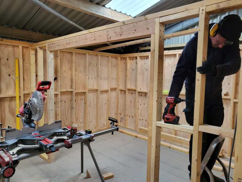
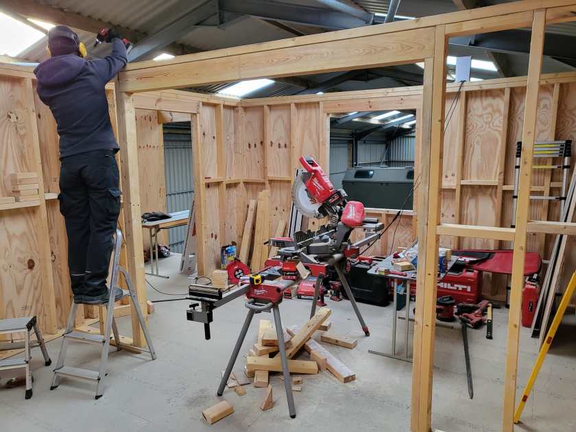
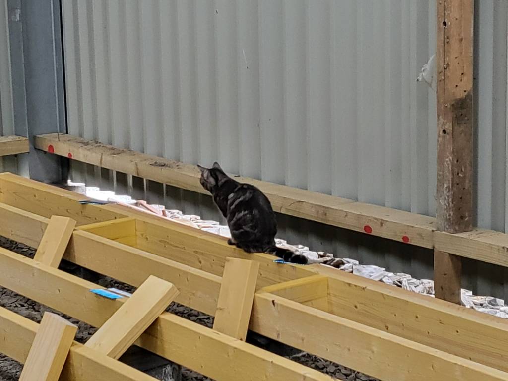
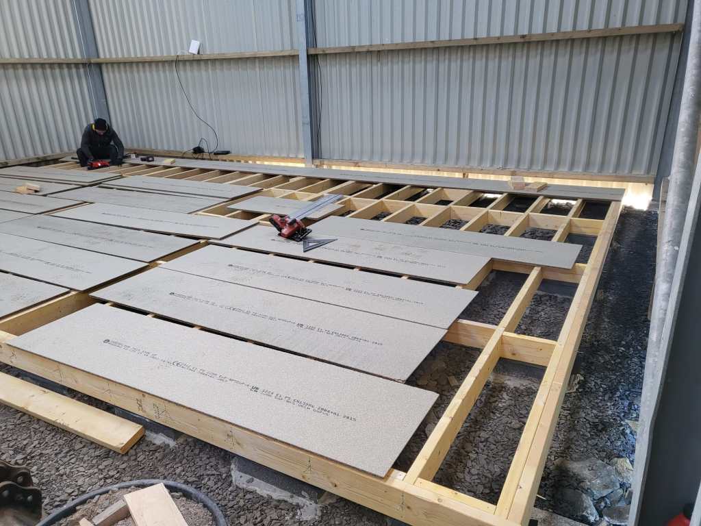
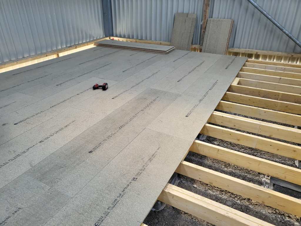
The Platform is finally done
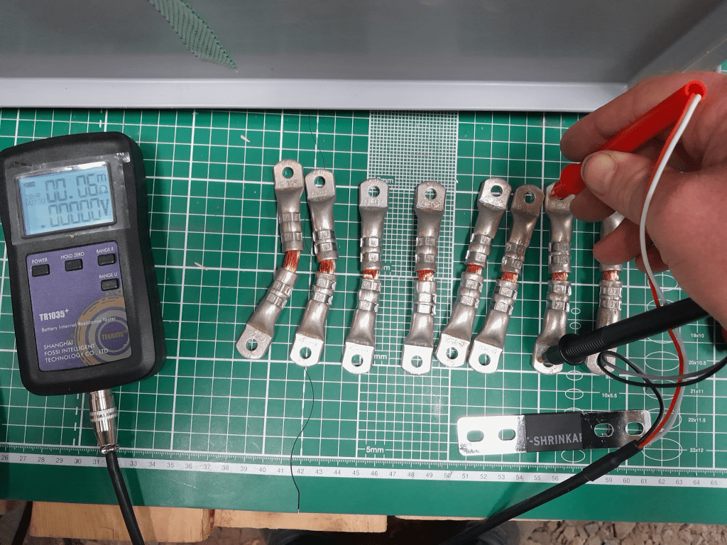
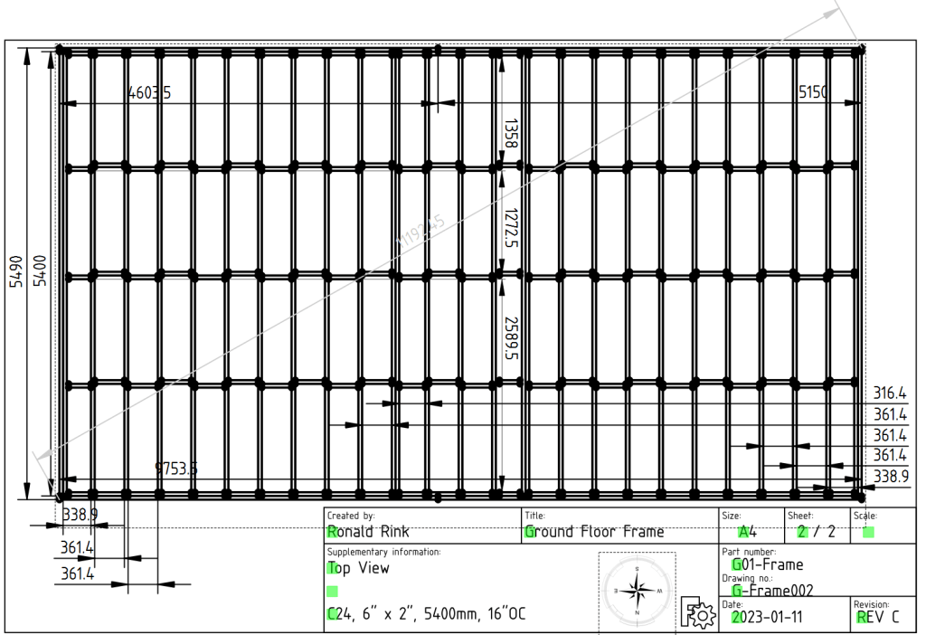
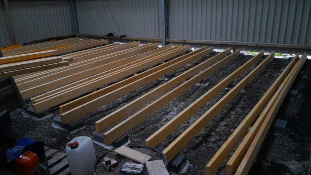
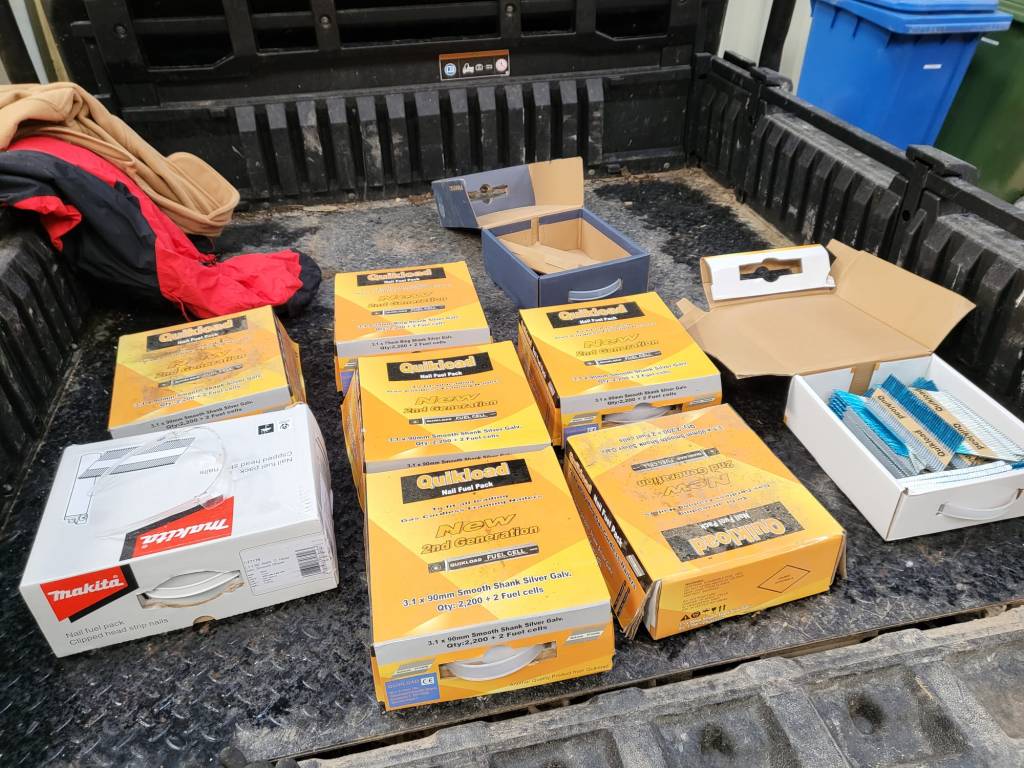
Last year in December, I started the drawings (with FreeCAD) for our “house-in-house” build: a wooden compartment inside our barn for electricity, water, storage and the like. But somehow, I never started it because of my mental concrete block (pun intended). This changed when a colleague of ours came by and helped me with laying the concrete pads. And from there we did the frame and the floor in less than 2 days – thanks to our Milwaukee Nailer and Larry Haun with his book The very efficient Carpenter.
Of course, there were some gotchas and mistakes needed to be fixed. But all in all it went really well. So well, that in fact we could have our first BBQ on the new platform (and not in the dust as usual).
So, below you find some pictures and drawings of the “house-in-house” and the making of the platform of the ground floor.


Electricity and our Saurer 2DM

This is sort of a never ending story for me – just as the installation of our workshop container on the truck bed by our trusty mechanic which has been “in the making” since October 2022.
It is clear that we want and need electricity in the container. Just how and how much is not clear yet. In the following, I will consider our rquirements and different apsects and constraints of the electrical installation to hopefully come to a conclusion. This is a rather dry article with a lot of numbers – so beware …
Here is what we know (or at least think we know):
- The truck has a
24Vsystem - Charging any “leisure” batteries via the truck engine on a regular basis does not seem to be a good idea, as the fuel consumption is already
33l/100kmwithout the container (that makes an astonishing8.56mpgin the UK) - It is a
EURO0diesel so we will not be able to get into all the cities (regardless of its problematic weight, length, height and width anyway). - Solar panels are still no real option (most of the time too way up in the North)
- Charging from an EVSE might not always be possible as most of these EVSEs are for cars and do not have space for trucks
- We want to be able to cook and wash in the vehicle
- We will have a
2kWdiesel heater - We will have a
900Wsingle phase petrol generator - We will be using Eve LF280K cells
- The inverter must at least provide
2'250VAor1'800W(concurrently, but not neccessarily on a single phase) - (optional) We would like to have 3-phase power in the container (as the cabling is already in place) – but also we know we would only use it very seldomly (such as for welding, then we need at least
11Aper phase) - We would like to be able to charge
60%of the batteries (from 20% to 80%) within3h - We will be using Victron MultiPlus-II (as we do not 2 separate AC inputs)
Here is a list of devices needing electricity:
- Refrigerator (able to run on 12V DC/24V DC or 230V AC)
- Microwave (
1'000W) - Water heater (immersion heater with
1'000Wor2'000Wand/or kettle with2'000W) - Table grill (
1'250W) - Steam cooker (
450W/900W) - Bread baking machine (
600W) - Coffee machine (
1'150W) - Washing machine (
750W) - Water pressuriation system (
850W) - Computers peripherals (USB-C charging with 36W via AC or DC, or 60W AC)
- Lights (12V or 24V DC)
- Water pump (12V or 24V DC)
- Fan (12V or 24V DC)
- Diesel heater (12V DC)
- Starlink (
60WAC, possibly 48V DC) - Infrared heating panel (
150WAC) - Battery charger (12V/24V DC or 230V AC, depending on model)
- Other USB powered and/or chargeable devices (via 12V/24V DC or separate 230V AC charger)
- built-in 6t winch (powered by engine)
- (optional) electric shower (
8'000W)
Sizing the electrical installation comes with a number of additional constraints:
- The crane in the workshop garage can lift up to
500kg
this mean, all batteries, inverters, washine machine and water tanks must be less that weight - No single battery can charge or discharge with more than
140A - We can only charge from EVSEs with a Type 2 connector
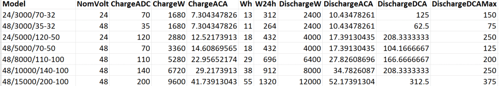
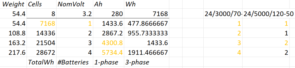
A 12V system is very quickly out of the picture (and the largest and only MultiPlus-II with 12V is a 3’000VA system). Besides, the truck has 24V system anyway. So it is either 24V or 48V. Here is an overview of all current 24V and 48V MultiPlus-II models and their charge and discharge values:
Let’s first evaluate a 24V system:
- 1* 8s battery
- Capacity is likely to be too small
- Single battery is not redundant
- 1*3’000VA can draw too much discharge current
- 1* 5’000VA can draw too much discharge current
- 2* 8s battery
- 2* 3’000VA can draw too much discharge current
- 1* 5’000VA possible
- 3* 8s battery
- 1-phase charge requirement can only be met with EVSE 7kW 32A Type 2
- 3* 3’000VA can draw too much discharge current
- 2* 5’000VA can draw too much discharge current
- 4* 8s battery
- 1-phase charge requirement can only be met with EVSE 7kW 32A Type 2
- 4* 3’000VA can draw too much discharge current
So, in a 24V 1-phase system only the 5'000VA inverter would be possible with either 2 (14’336Wh) or 4 (28’673Wh) batteries.
For a 3-phase setup to support our Kemppi Kempact 253A we would need at least 4 batteries and 3* 5'000VA inverters.
And now let’s have a look at a 48V system where we have a couple of more inverter options:

- 1* 16s battery
- Single battery is not redundant
- 2* 3’000VA inverters needed
- 1* 5’000VA inverter possible
- 1* 8’000VA can draw too much discharge current
- 1* 10’000VA can draw too much discharge current
- 1* 15’000VA can draw too much discharge current
- 2* 16s battery
- 1-phase charge requirement can only be met with EVSE 7kW 32A Type 2
- 3’000VA not as 3-phase setup feasible (otherwise 6 devices necessary)
- 8’000VA only as 3-phase setup, but then too heavy
- 1* 10’000VA possible
- 1* 15’000VA can draw too much discharge current
- 3* 16s battery
- 1-phase charge requirement cannot be met
- charge requirement can only be met with 3-phase EVSE (16A or 32A) Type 2 (11kW+)
- 3’000VA possible, but too heavy with combined battery weight
- 5’000VA possible
- 8’000VA only as 3-phase setup, but then too heavy
- 10’000VA only as 3-phase setup, but then too heavy
- 15’000VA possible
- 4* 16s battery
- batteries too heavy
- 1-phase charge requirement cannot be met
- charge requirement can only be met with 3-phase EVSE (16A or 32A) Type 2 (11kW+)
- 3’000VA too heavy with combined battery weight
- 5’000VA too heavy with combined battery weight
- 8’000VA only as 3-phase setup, but then too heavy
- 10’000VA only as 3-phase setup, but then too heavy
- 15’000VA only as 3-phase setup, but then too heavy
So, this leaves us with really 3+2 choices:
- 2* 8s (14’336Wh) batteries in a 1-phase system with a single 5’000VA inverter
- Battery and inverters would weigh roughly
140kg
- Battery and inverters would weigh roughly
- 2* 8s (14’336Wh) batteries in a 3-phase system with three 5’000VA inverters
- Battery and inverters would weigh roughly
250kg - Not possible for 3-phase welding
- Battery and inverters would weigh roughly
- 4* 8s (28’672Wh) batteries in a 3-phase system with three 5’000VA inverters
- Battery and inverters would weigh roughly
310kg
- Battery and inverters would weigh roughly
- 1* 16s (14’336Wh) battery in a 1-phase system with a single 5’000VA inverter
- Battery and inverter would weigh roughly
140kg
- Battery and inverter would weigh roughly
- 2* 16s (28’672Wh) batteries in a 3-phase system with three 5’000VA inverters
- Battery and inverters would weigh roughly
310kg - 3h on a 1-phase 16A Type 2 would charge about 38% (a 60% charge takes 4.7h)
- Battery and inverters would weigh roughly
From there, we can narrow this down even further:
1-phasesystem:24V, 2*8s- Price: batteries 2* 1’364GBP = 2’728CHF plus inverter 1* 1’359GBP total =
4'087GBP- Con: 24V MultiPlus-II are considerably more expensive (than 48V)
- Con: only have the capacity
- Con: cannot run electric shower
- Price: batteries 2* 1’364GBP = 2’728CHF plus inverter 1* 1’359GBP total =
3-phasesystem:48V, 2* 16s- Price: batteries 4* 1’364GBP = 5’456CHF plus inverter 3* 812GBP = 2’436GBP total =
8'802GBP- Con: charge requirement can only be met with 32A Type2 on 1-phase
- Con: additional 48V|24V DC-DC converter required
- Con: heavier, 300kg+
Con: higher self-consumption in 3-phase configuration
- Price: batteries 4* 1’364GBP = 5’456CHF plus inverter 3* 812GBP = 2’436GBP total =
So – drum roll – my conclusion: for roughly double the money in a 48V we would get double the capacity and triple the charge and output power and pretty much can do everything we want the system to be able to do.
The 3-phase system can be reconfigured to a parallel 1-phase system, so we would even be able to use an electric shower (though very unlikely – we have our mobile shower). We can either charge 1-phase or 3-phase and have a longer window of electric autarky. And for most of the time we would leave the system in a 1-phase single device InverterCharger configuration. And additionally, for charging the other 2 devices would bet set to ChargeOnly (but be configured independently configured from each other).
The exact setup I will have to layout some other time, but right out of my head I would think of the following components:
- External power in with CEE 16-5, CEE32-5, CEE32-1, CEE16-1 and Neutrik PowerCON True1 TOP (the more the better)
connected to an ATS - AC out from MultiPlus-II connected to ATS
- Orion-Tr 24V|48V DC-DC converter
charging from alternator (though not the norm) - Orion-Tr 48V|24V DC-DC converter
as power supply: to support 24V loads in the container
as charger: as an emergency charger for the truck batteries - Lynx Power In, Distributor
- Venus OS with Raspberry PI for RS-486 and DVCC
So, in case our Saurer ever gets finished – at least I know how to do the electricity …
The way of the bin

Finally, they arrived! We now have bins from the Highland Council. This means, we no longer have to drive to the Wick Recycling Centre to dipose our waste. What a convenience! For us this is another milestone (after getting a postal address, the Planning and the barn built).
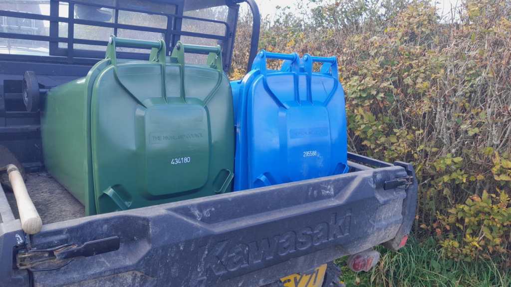
As our plot is not exactly reachable by the bin men we now drive them to the main road – 440m to be exact. Though this may sound tiresome, but it is still way faster than to drive to the recycling centre.


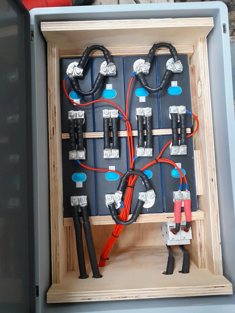
Building a battery case for an 16s Eve LF280K configuration
The other day, I realised that I never wrote about the case build of our 16s 48V batteries, as I did for the 8s case and the 4s case. So, here it is – and I am actually describing 2 revisions as we made some adjustments.
First, the total weight of the cells alone would be roughly 16 * 5.3kg ~ 85kg. This is way beyond what a single person can – or at least should – lift. So, I deciced to split the battery into 2 separate cell blocks of 8 cells each (similar as I did split the 8s battery in the Toyota HiAce). With this approach, I would be able to:
- reuse the 8s design (including the RAKO boxes)
- be able to move or lift half a battery (which weighs roughly
53kg)
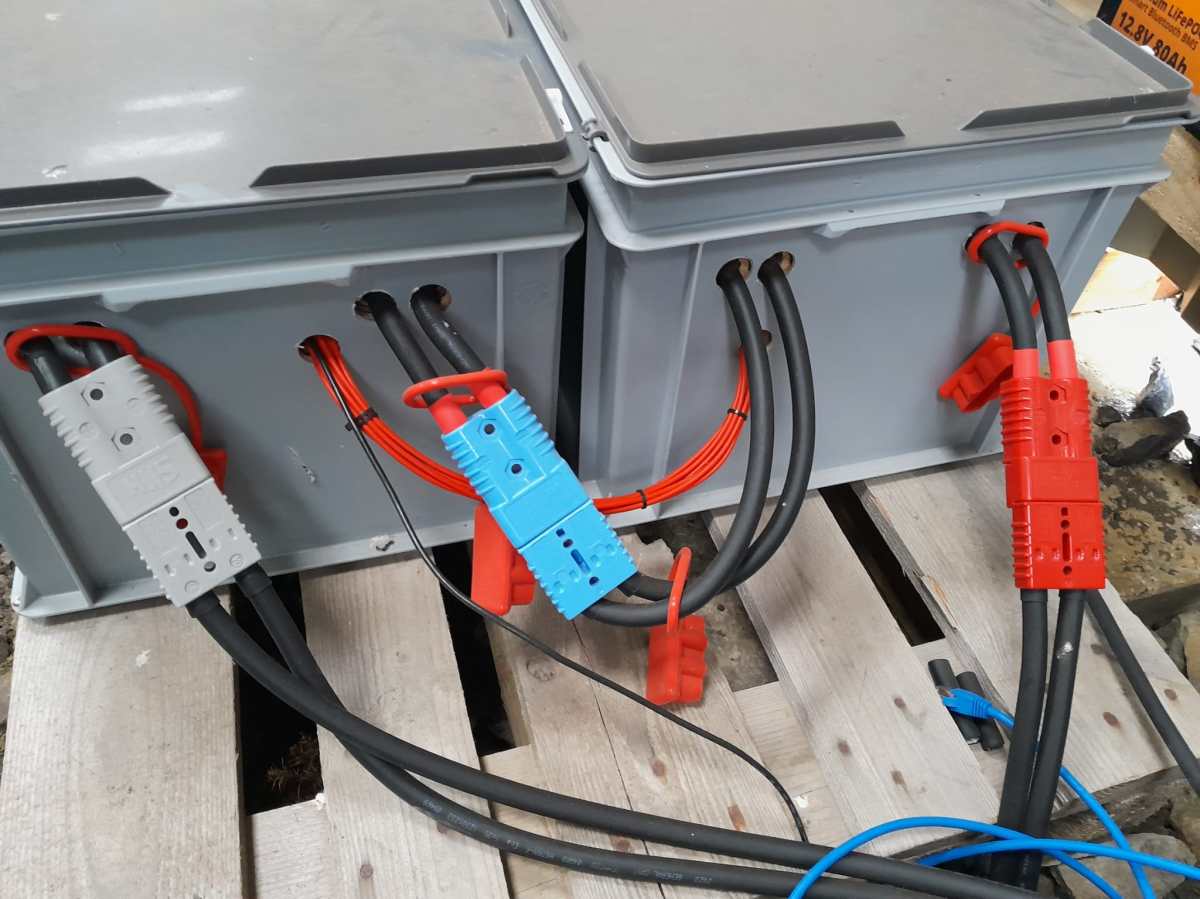
This battery has a nominal capacity of 3.2V * 16 * 280Ah = 14'336Wh and can be charged or discharge with up to 140A ^= 7'168W. We currently have 2 of these batteries running on our 3-phase setup with 3 * Victron MultiPlus-II 48/5000/70-50.
So essentially, I built 2 8s batteries with a connection cable between cells 8 and 9. The main negative and the BMS would be in one box and the main positive with the DC breakers would be in the other box. To avoid confusion, in this setup I went for coloured Anderson SB175 housings, with
- Red
2 * 35mm2H07RN-F cable main positive - Grey
2 * 35mm2H07RN-F cable main negative - Blue
Interconnecting both blocks2 * 35mm2H07RN-F cable connecting from cell 9 positive to cell 8 negative
In all cases

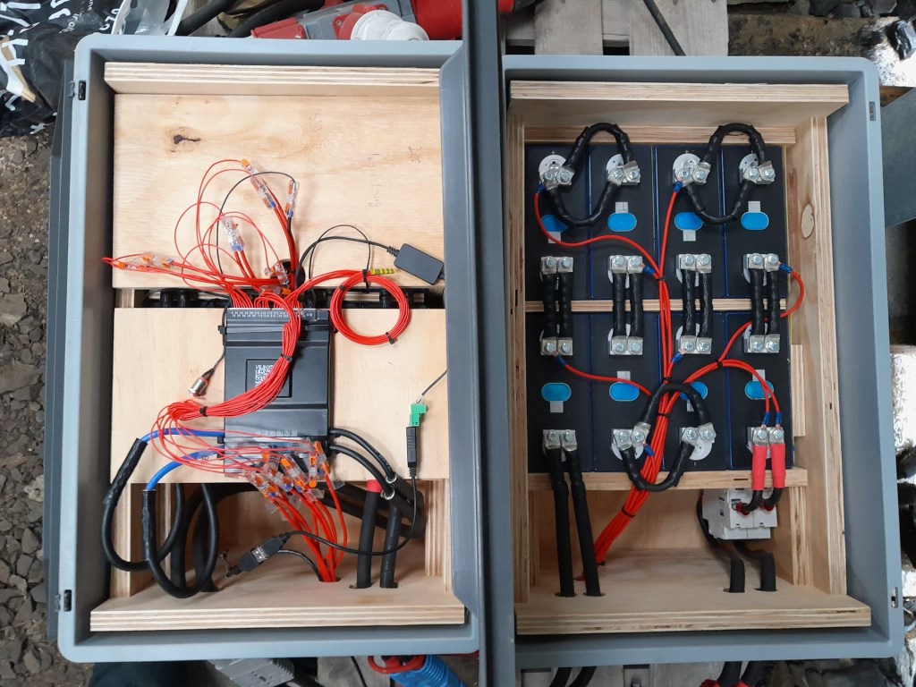
To connect the cells to the BMS balancer cables I extended the balancer cables with 2.5mm2 wire via WAGO 221-2411 inline splicing connectors. I then measured the increased resistance of the additional cable length and adjusted the values in the BMS configuration for cells 1 to 9.
With these inline connectors I am now able to disconnect the blocks from each other so I can move them around independently, if needed.
On the BMS, I connected a USB RS-485 TTL adapater with a USB extension cable which leads to one of the USB ports of the Victron Cerbo GX. With the help of dbus-serialbattery and BatteryAggregator I can control the DVCC settings in Venus OS.
The rest of the build is, as I already mentioned, pretty much like the 8s build.
Revision 1
Here are some images of the completed build of revision 1.

Revision 2
These are the changes I am currently making for the next revision:
- add additional connectors for the balancer cables to further facilitate the disconnection of both blocks;
- use
16mm2M6 Klauke DIN46235 compression cable lugs for the connection of the main negative (cell 16) to theB-of the BMS (only relevant to the older JK-BMS), to be able to disconnect and potentionally replace the BMS; - use a WAGO
35mm2DIN rail connector in the main negative block on cell 1/9 for the outgoing cable; - use cable glands on the external connections;
(this allows for easy disconnection and re-building the block as an 8s battery); - use ratchet straps for compressing and mounting the cells to enable easier maintainability of the cells;
- use Anderson PowerPole PP180 connectors instead of SB175, so I can use mounting plates for the PP180 and do not have dangling cables on the outside of the case
(these connectors are expensive and increase the price of the overall build by roughly60GBP).
