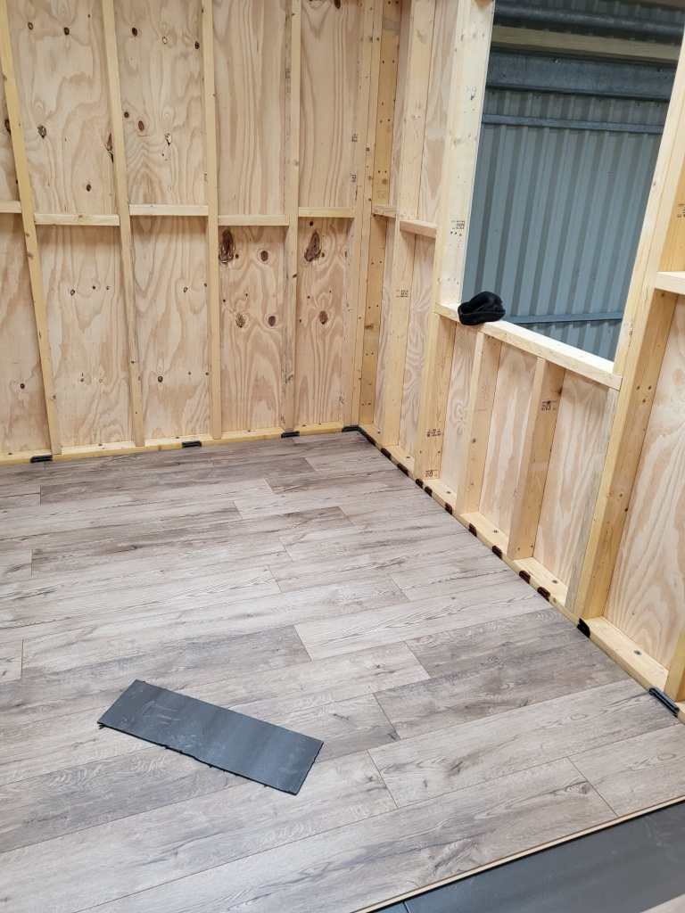
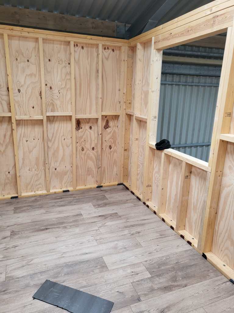
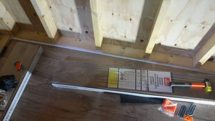
Here is a quick overview of the current state of our laminate flooring: By now, we completed the kitchen, the bathroom, the bed room and the study.
Still to do: utility room, storage room, living room and two hallways. So, not quite there yet.
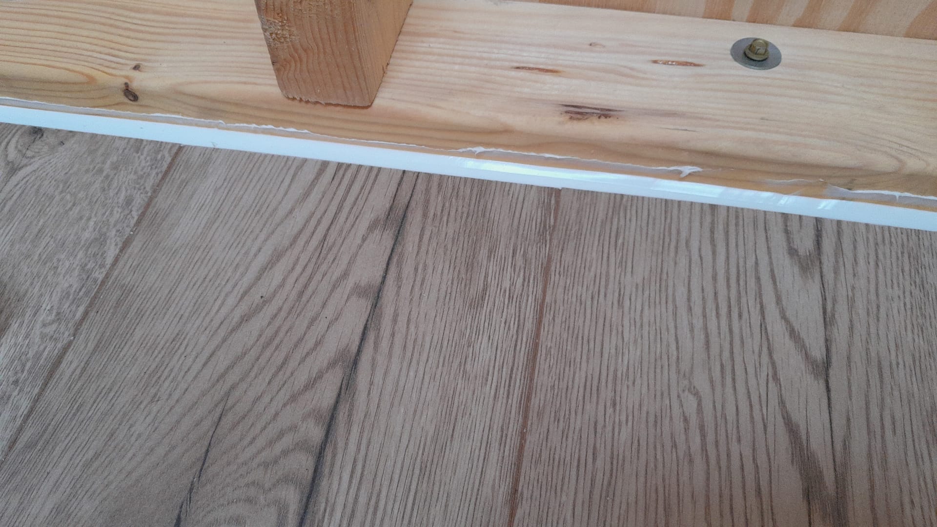
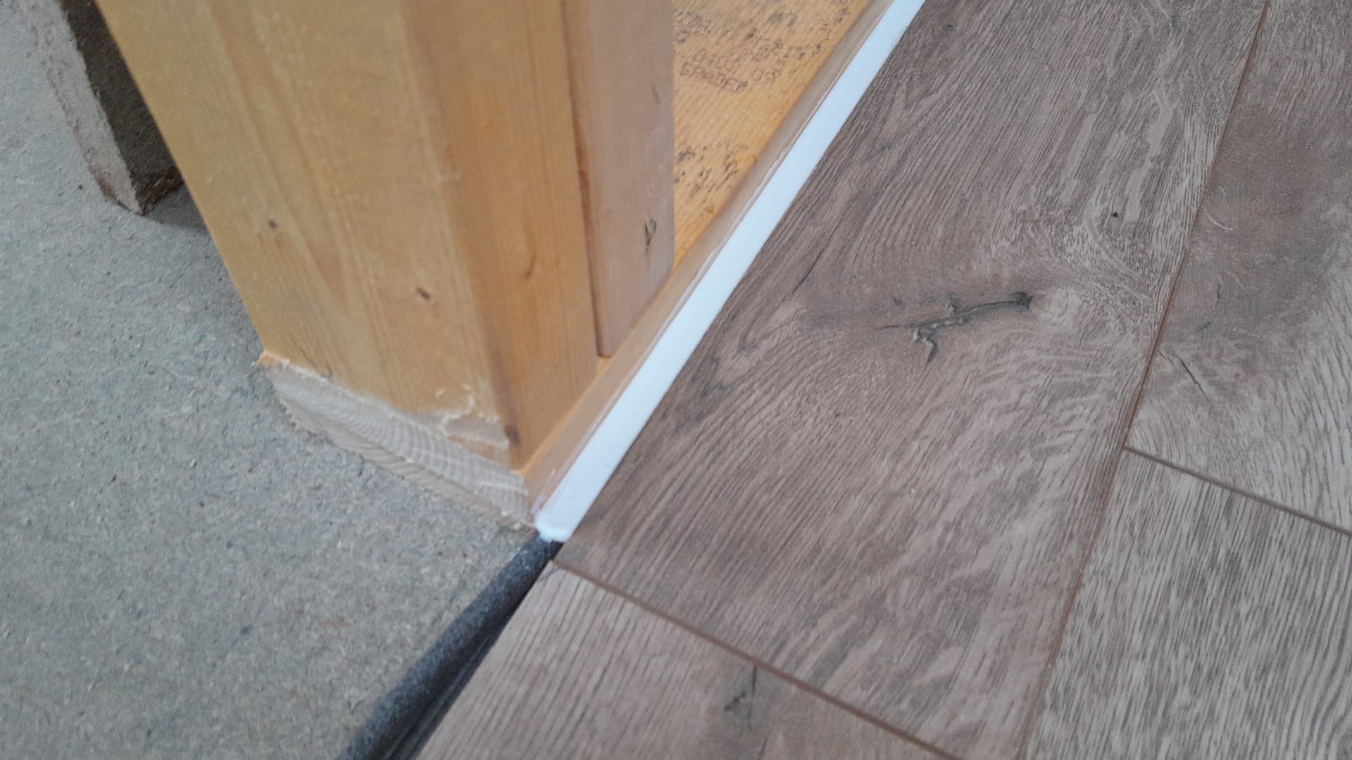
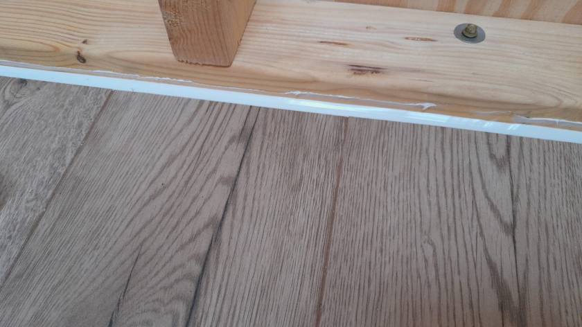
Our initial silicone tests showed we would use way too much silicone (around 6* 310ml per small room) to fill the required 12mm gap between the laminate and the wall. So, we went for a 10mm foam backing rod and put the silicone on top – with the help of a Hilti Dispenser and Fugenfux. We got the silicone from Screwfix: Sanitary Silicone White 310ml 12 Pack. And the result looks like this:
Laminate with silicone without skirtingStill improving the corners …Silicone with backing rod
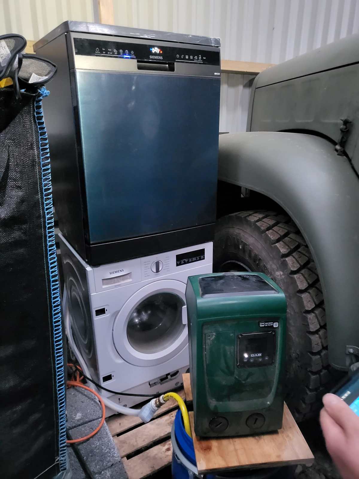
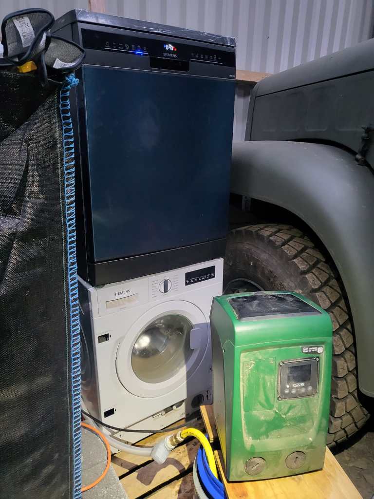
We definitely moved beyond Maslow’s pyramid and introduced a dishwasher to our ever growing list of utilities – which by the way fits nicely next to our Saurer 2DM … It is a Siemens iQ300 SN23EC03ME which is also driven by our DAB Esybox Mini 3.
What we found out so far:
Water consumption is much higher than advertised even when using the 45°C/45min programme.
Power consumption seems slightly higher than advertised as well with a peak consumption of around 2200W.
But all in all, we still save time, water *and* power compared to washing up by hand. And this holds true even for much less energy efficient dishwashers with an energy star rating of D or worse.
So, next time I buy a dishwasher I think twice if I spend a 100 quid extra on a more power efficient device – especially, when using solar for most of the year …
Dishwsher Siemens iQ300 SN23EC03ME on top of a washing machine driven by a DAB Esybox Mini 3
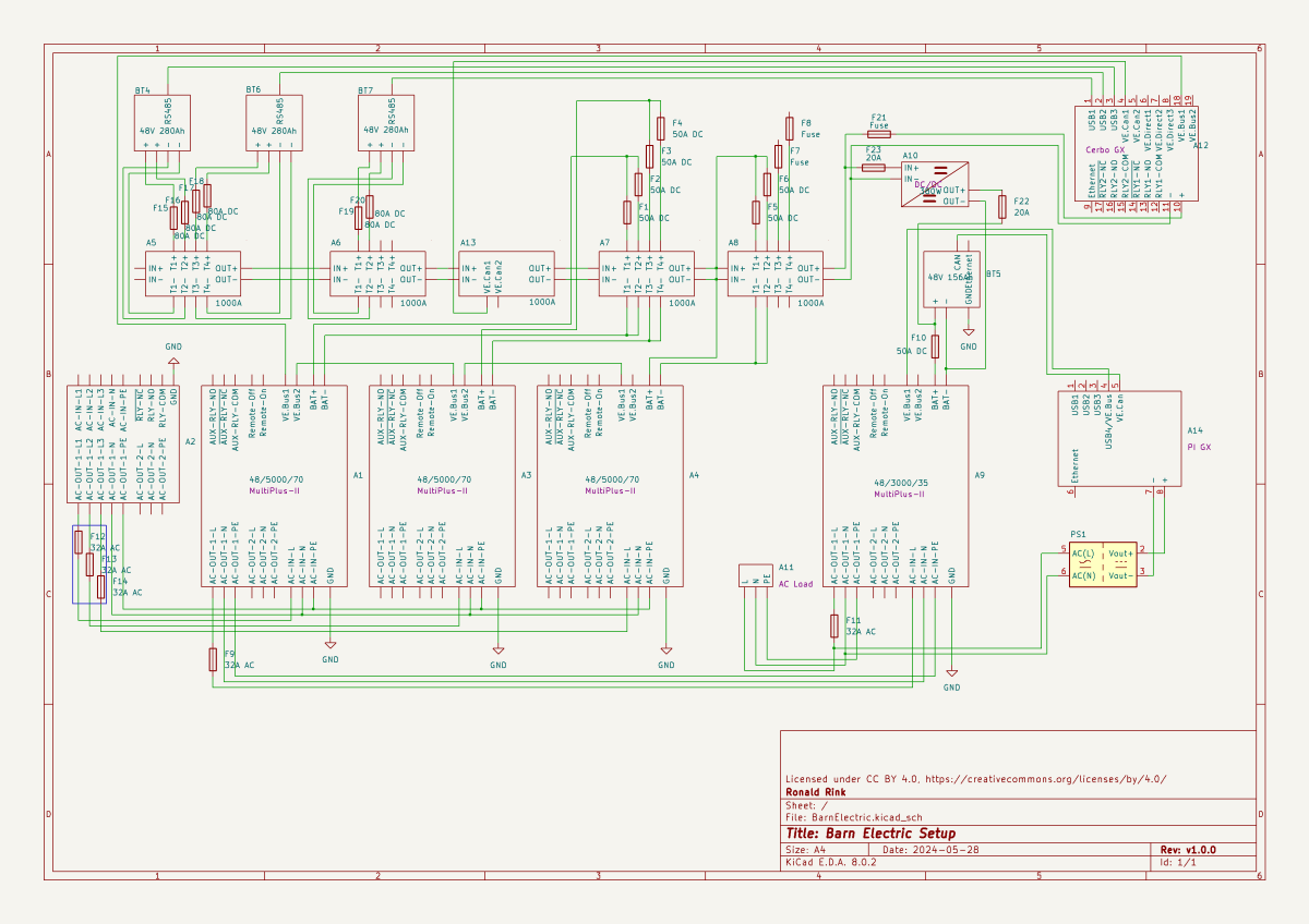
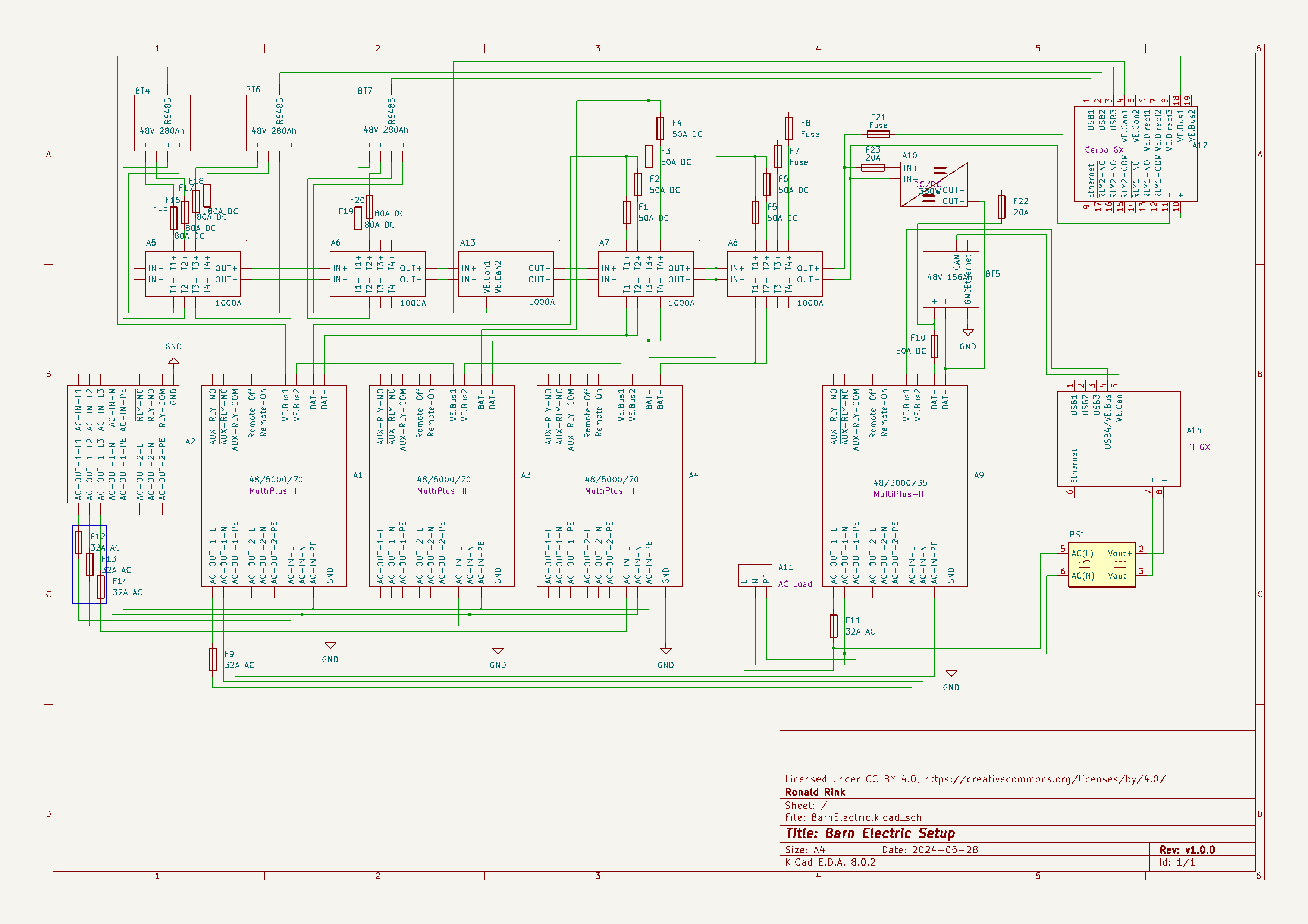
I recently wrote about our upcoming solar PV adventure. But before updating our system, I thought it was time to document and explain our current setup (with the help of KiCad).
This system is the main electricity for our barn and currently consists of three batteries with an energy (often referred to as “capacity”) of 3* 14.33kWh = 43kWh (battery bank A, A1:A2 on the plan). These batteries are charged by a JCB G20QS (B1) via three MultiPlus-II 48/5000/70 inverters/chargers (B1:C2) which are by default in “Charge Only” mode. The MultiPlus-II are configured in a 3-phase configuration but only turned on when 3-phase is actually needed.
The main power is delivered by a MultiPlus-II 48/3000/35 (B4:C5) that is connected to a separate battery bank (battery bank B, BYD LVS Premium Battery-Box with an energy of 8kWh). This latter MultiPlus-II is connected to L1 of the 3-phase MultiPlus-II. So, whenever the main batteries get charged the cascaded inverter will also be charged. In addition, we can then use PowerAssist to up to supply 8'000VA (= 5'000VA + 3'000VA) when running on batteries and up to 14'500VA (= 6'500VA + 5'000VA + 3000VA) on a single phase.
Though the generator can supply up 14'400W the chargers of the Multiplus-II can only charge with a power of up to 3* 48V* 70A = 10'080W. This is actually an advantage as the optimal efficiency factor of the generator is roughly at 12'000W. So with 210A we are pretty close. If we ever added more chargers to the system we could even slightly increase the charge current to 250A.
System A with the 3-phase inverter configuration is connected to a Lynx bus bar (A1:B4) that also includes a Lynx shunt (B3) used for measuring over all batteries. In addition, there is an islolated Orion-Tr DC-DC charger (A5) that constantly feeds system B.
System A and B are connected to their separate GX:
system A Cerbo GX, A5:A6 MultiPlus-II via VE.Bus, Lynx Shunt via VE.Can, JK-BMS via RS485/USB
system B Raspberry Pi4running VenusOS, B5:B6 MultiPlus-II via VE.Bus, BYD BMS via VE.Can (on a Pi GPIO Hat)
And this is it for the electricity installation in our barn.
Note: This cascaded setup is officially not supported by Victron, but it has been working for us without problems for months now. This might be different in your case.
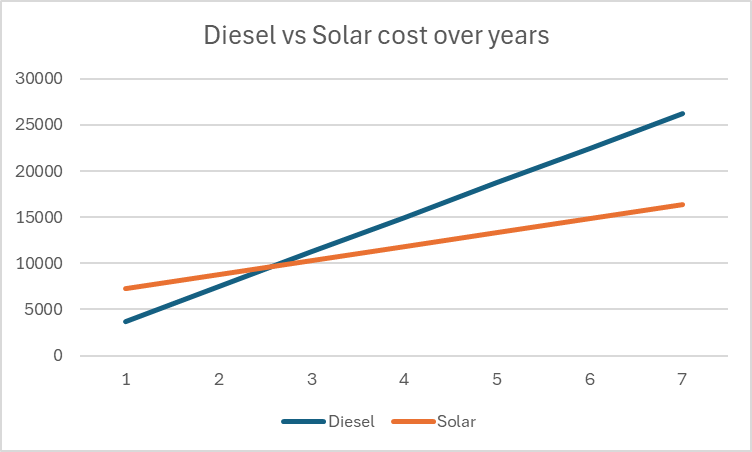
We finally did it and decided to get a PV system for our barn. Though we had been thinking about this since we started building on our plot, it never seemed to really pay off. A solar installation in very north of the Highlands?! But with prices for PV modules falling and falling I did another “business case” to see where this would land.
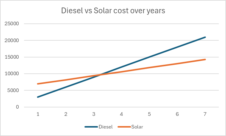
In the following figure you see the condensed outcome. In 38 months we would “break even” and roughly save over a 950 GBP per year over the course of seven years.
Diesel vs Solar cost over the years
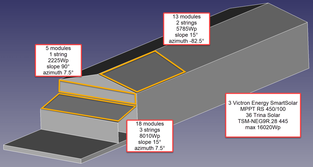
Selecting Modules for the Roof
But first, let me begin from the beginning … for the last two years our JCB G20QS backup generator has been sitting outside in the rain and collecting not dust but rust – that is why we decided to build a small shelter on the south end of our barn. Once we finished drawing the shelter with its 36m2 roof, we thought that a south-facing roof would be perfect for collecting solar energy in the summer. Remembering my last calculation, I knew that the slope of the panels for winter and summer time differed dramatically. That was when we started thinking to place additional modules vertically on the south wall of the barn.
After we realised how much sheet metal for roofing would cost, we looked for for cheap solar modules that could be used as a cover for our shelter. We selected the Trina Solar TSM-NEG9R.28445Wp module with dimensions of 1762mm x 1134mm x 30mm that would fit well as a roof.
Selecting MPPT Chargers
With the PV modules selected I had to choose between a AC-coupled and an DC-coupled system or a mix between the two. As our system is off-grid and I expected fast-changing workloads in our environment I decided for a completely DC-coupled system.
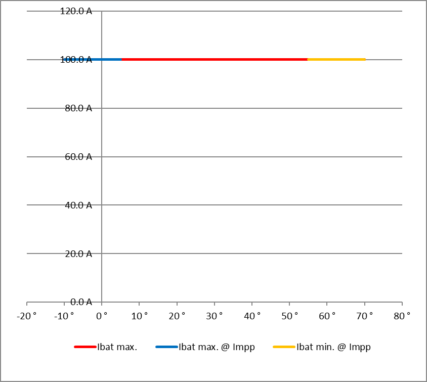
Already running a Victron system, I wanted to use Victron MPPT chargers for the installation. After checking and comparing the prices of different chargers (with a VE.Can or a VE.Direct connection), I started the Victron Energy MPPT Calculator and added my solar panels to it. I then did a couple of modifications to the spreadsheet (by prior removing the password and protection from the sheets) and found the Victron Energy SmartSolar RS 450/100 to be the best choice. With this charger I could fit 7 modules per string in order not to exceed Voc. The power would be limited by over 30A at minimum temperature but I do not expect much sun in the colder months anyway. At max temperature there would also be a cap by roughy 15A but I expect to have large amounts of excess energy during the sunnier months – so need to worry.
Calculation for Trina Solar 445Wp modules with dual tracker RS 450/100 (Victron Energy MPPT calculator)Input voltage per stringCharge current per MPPT charger
Note1: there seems to be a bug in the spreadsheet version BHO 01-2021 4.0 when using the “MPPT RS” tab. The calculation table uses the selected voltage in cell E15 from the “Blue- & SmartSolar” tab (and not 48V as the only possible voltage for the RS) and from there miscalculates the currents.
Note2: when selecting the number of modules and the diameter of the cabling, the up/down buttons do not seem to work correctly. Typing the values directly into D16, D33, K18, J35 and K35 works around this issue.
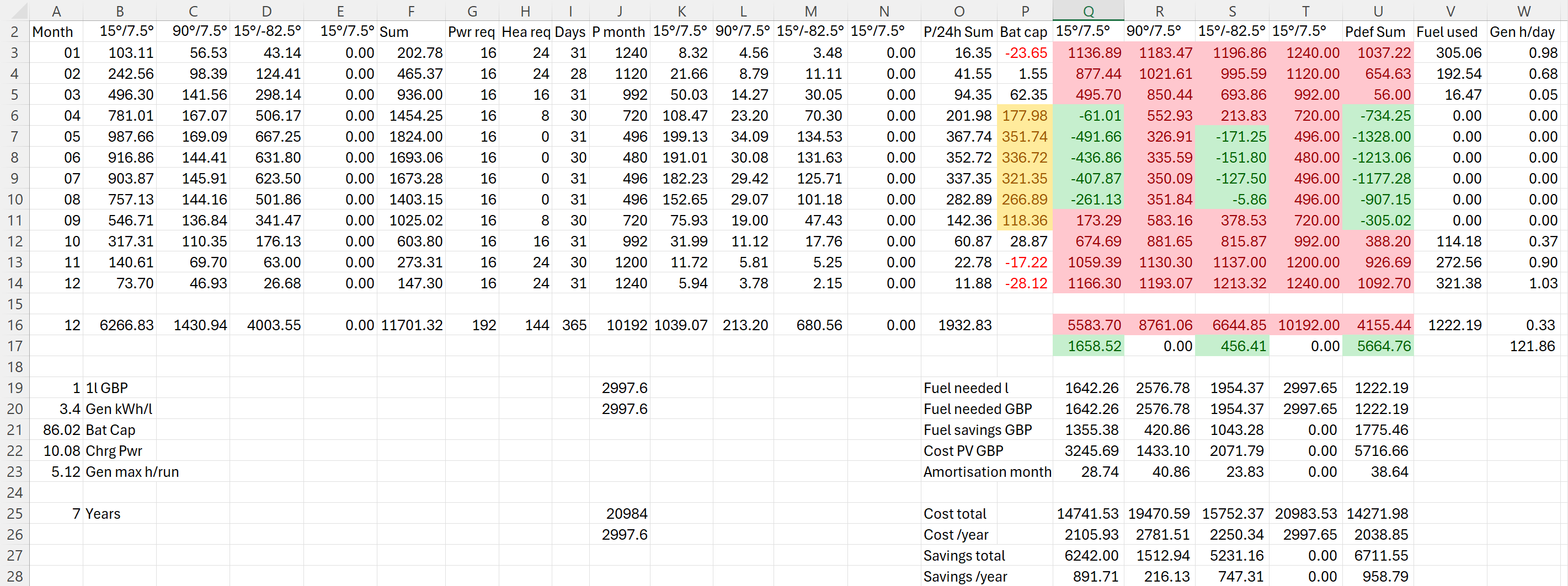
I then combined the info into a table to see if and how much energy could be produced. For this I estimated the amount of energy I would need in the forseeable future per month (electricity and heating) which varies between 480kWh and 1'240kWh.
Note: currently we do not need even 25% of that amount.
The numbers with red background reflect the energy deficit for that month. Numbers with green background show an excess power production for that month. The total of all panels is shown in column U. From there it is compared against our generator which would roughly need 0.3l/kWh (row 26).
Power generation and consumption in comparison
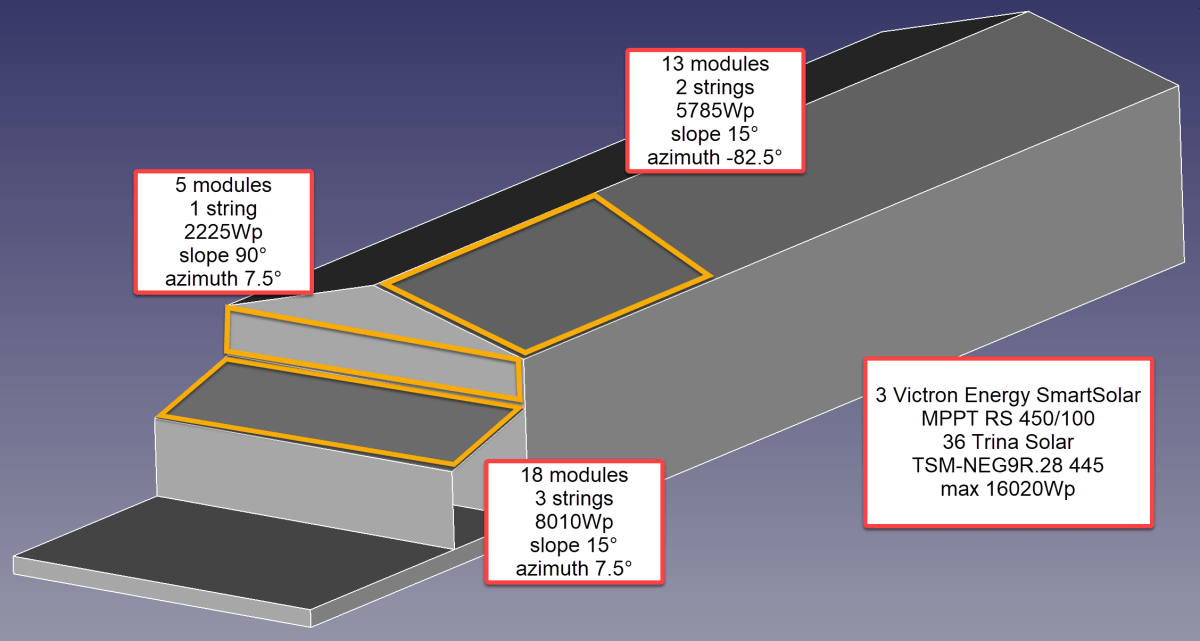
So, for the first part of the installation I will add 36 modules on 6 strings as you can see from the image below.
Overview of planned installation
Anticipating Change
It is interesting to see how a 25% increase of diesel cost changes the picture:
Diesel vs Solar cost over years with 25% increase in fuel cost
As we still have space for more modules on our east-facing barn roof, I could add another set of (larger) modules. And this would reduce fuel consumption by approx. 20% by deferring the “break even” to 55 months!
Prediction with additional panels on the east-facing barn roof: 20% fuel rduction
But it gets interesting when we take rising fuel cost into account.
Prediction with additional modules on the east-facing barn roof: 55 months “break even”Prediction with additional modules on the east-facing barn roof: 25% increased fuel cost
With these additional modules we could run the whole winter with only one filling of our diesel tank and thus avoiding a costly refill during the winter season. So, this is something to be considered for the future.
Distributing Modules
Before wrapping it up, I will quickly motivate why I chose three SmartSolar RS 450/100 instead of one SmartSolar RS450/100 and one SmartSolar RS 450/200 and their connetion to the modules. With three instead of only two devices the average power reduction during a failure is only 33% instead of 50%. Power limiting is not such an issue, as the strings will be connected as follows:
Charger 1 117.3 A min temp / 96.2A max temp string 1: 5 modules 90°/7.5° south wall string 2: 7 modules 15°/-82.5° east roof
Charger 2 117.6 A min temp / 96.4A max temp string 1: 6 modules 15°/-82.5° east roof string 2: 6 modules 15°/7.5° south roof
Charger 3 117.6 A min temp / 96.4A max temp string 1: 6 modules 15°/7.5° south roof string 2: 6 modules 15°/7.5° south roof
Conclusion
I certainly do not know how much energy will really be produced. But it is clear, that I will have excess power in the summer when I do not need it and not enough power in the winter when I need it.
Additionally, I merely save a 950 GBP per year – not taking into account:
that I already have a required inverters, bus bars etc;
any labour on my side to design and install the system;
that the system gets more complex and error prone.
So, in reality I probably do not really save much to anything with this installation, as Diesel is still way too cheap. Though I certainly benefit from that, it is actually a shame. There should be more incentives for cleaner power generation.
As a side note: In case you missed why we went for a generator in the first place., here is why. The quote from the power company for a grid connection was way over 35’000 GBP. For this amount I can easily buy a generator, inverters, batteries and even solar modules.
And I already have an idea what to do with all the energy during the summer months that we really do not need: brewing a red ale with green energy …
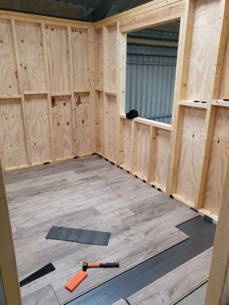
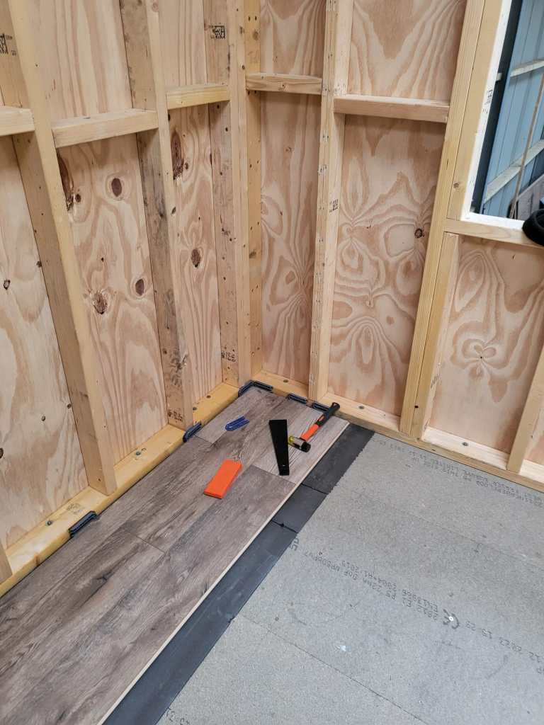
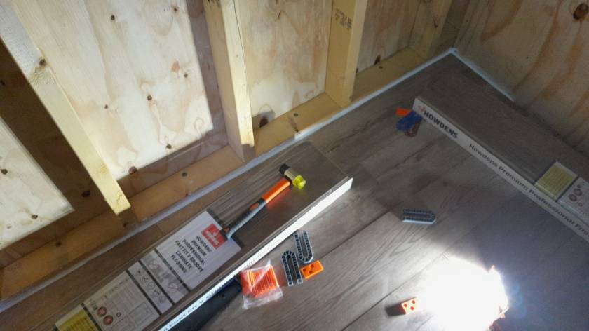
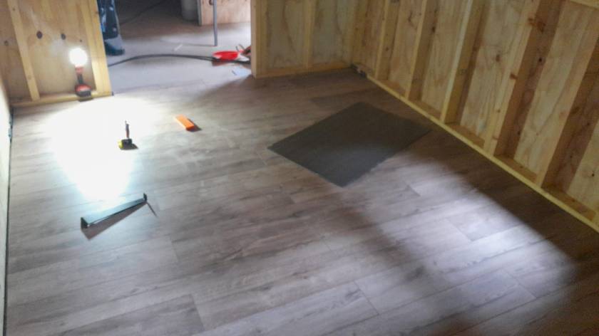
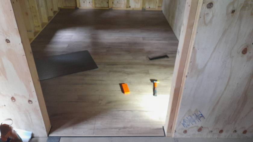
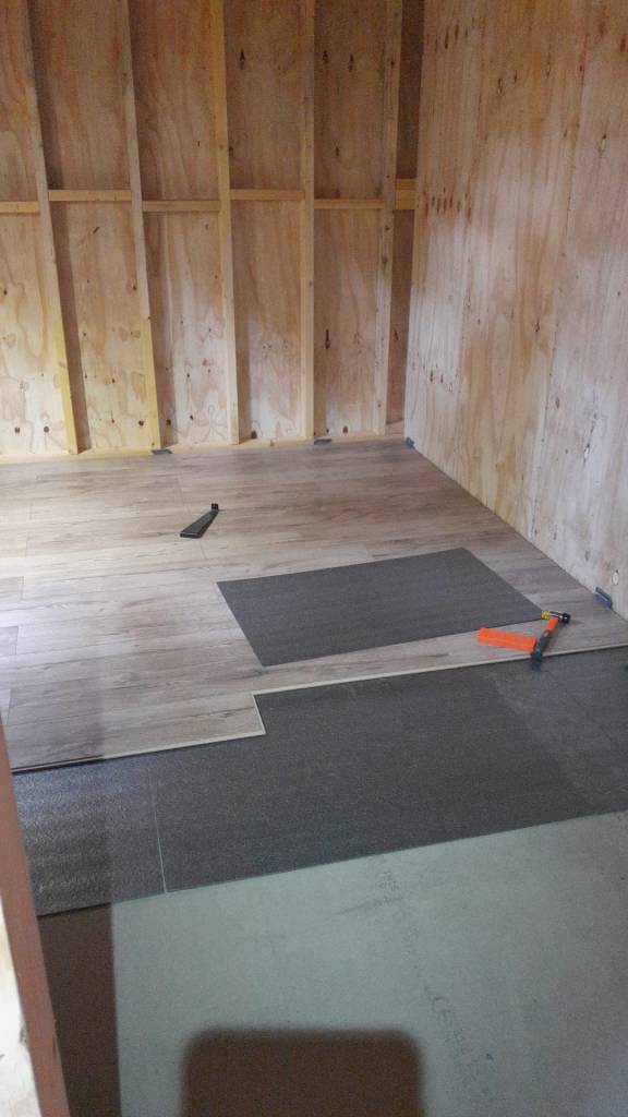
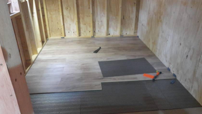
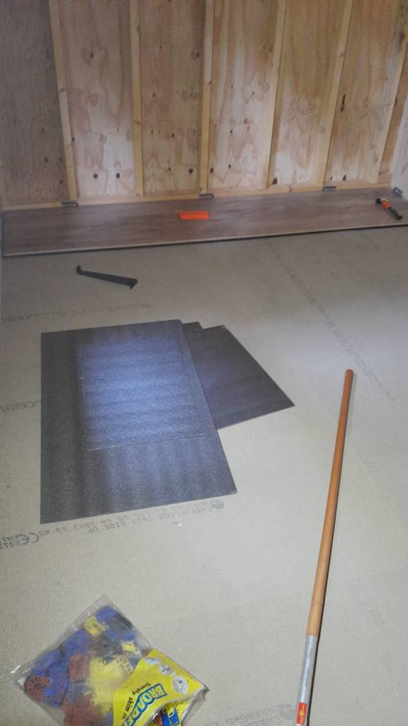
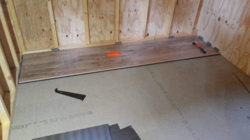
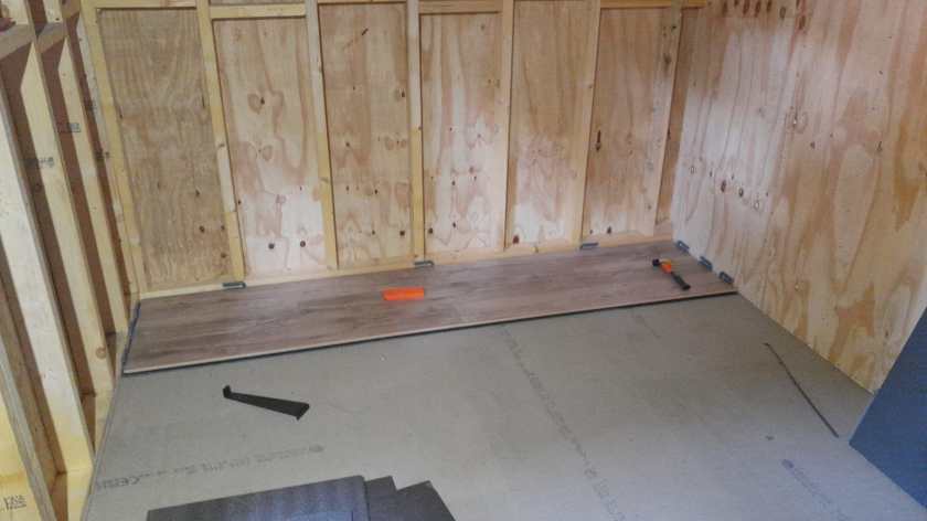
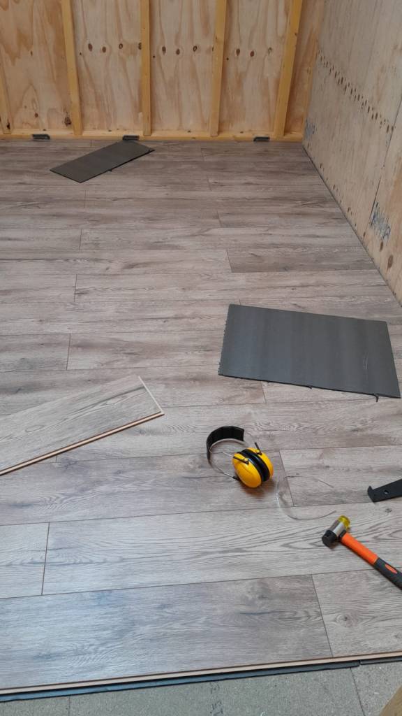
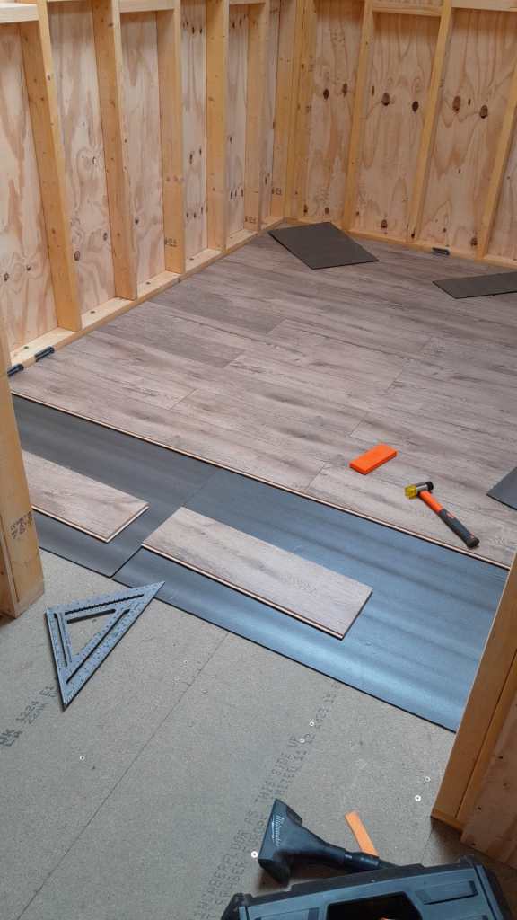
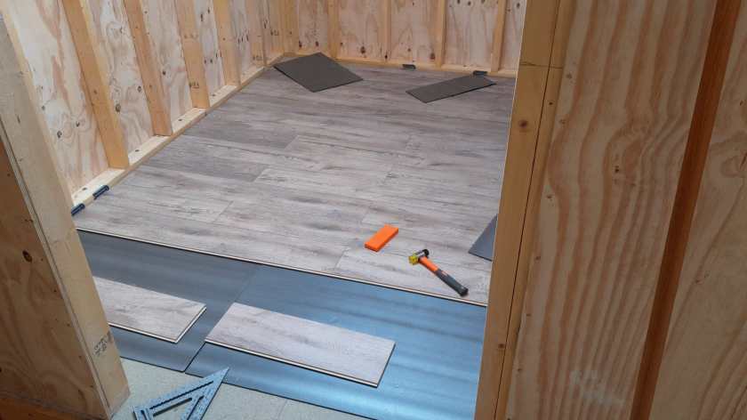
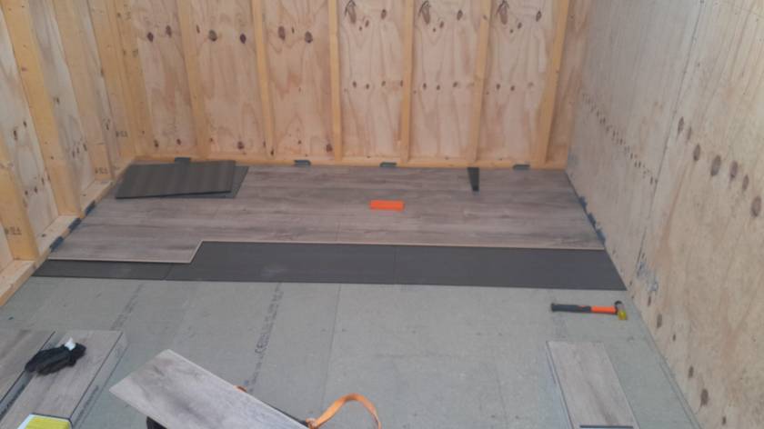
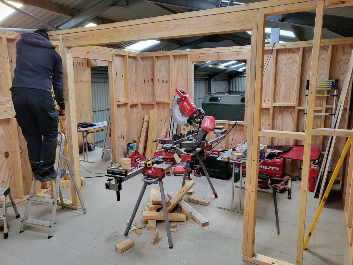
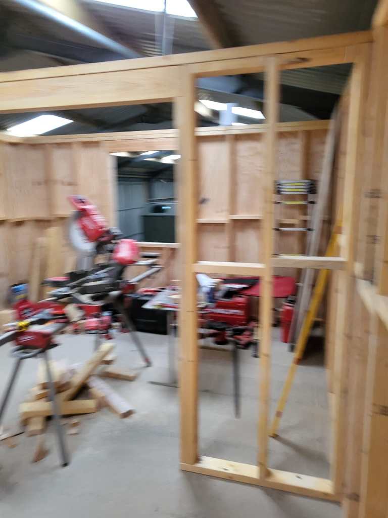
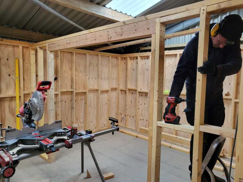
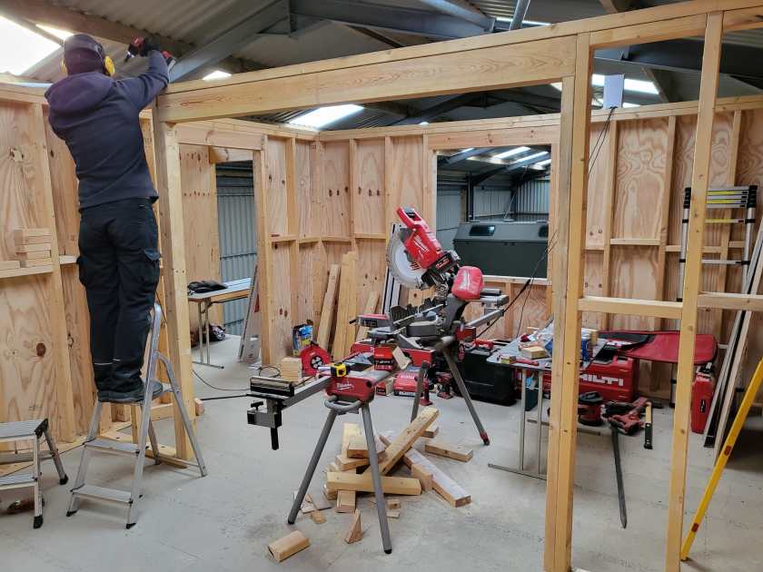
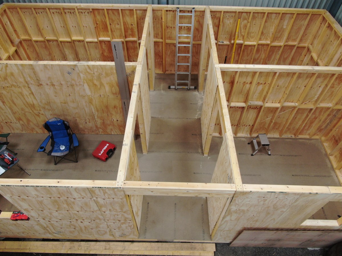
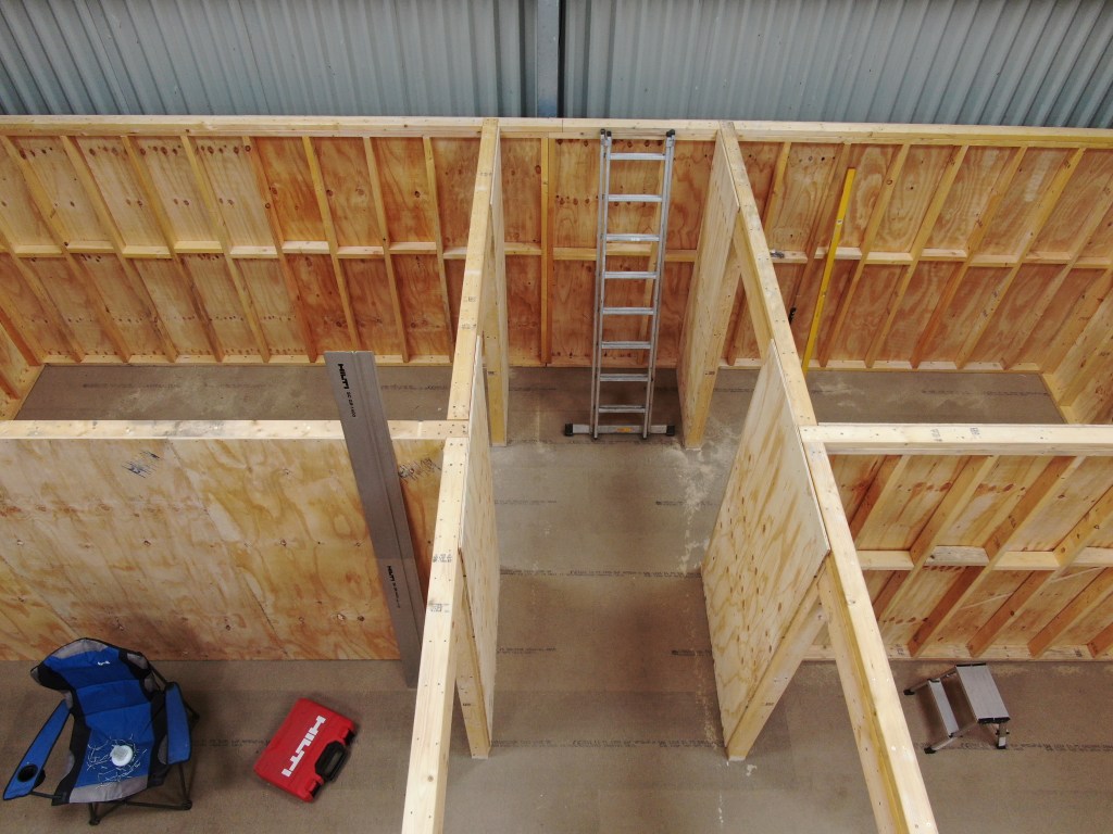
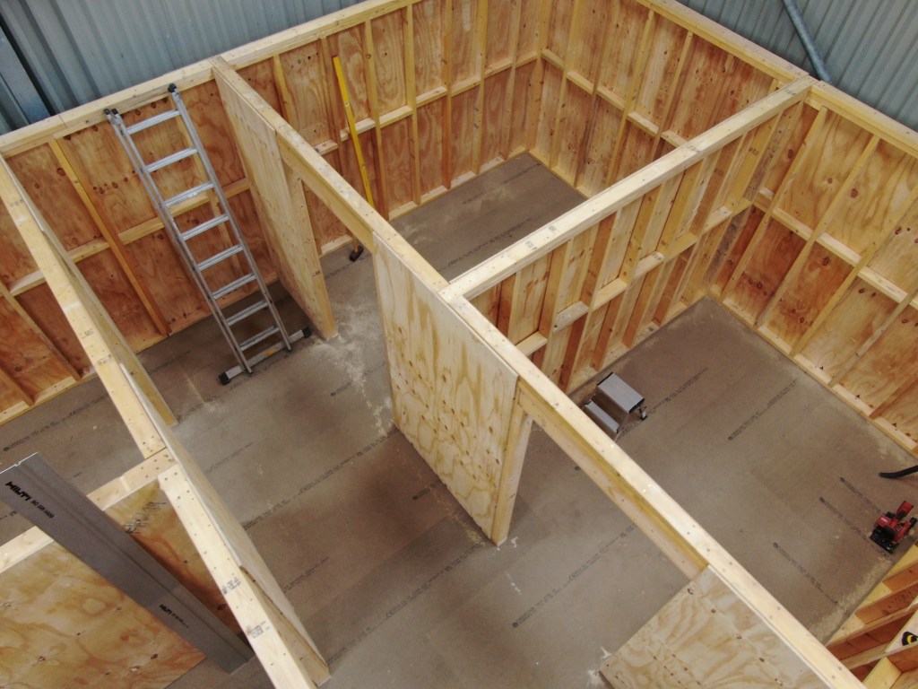
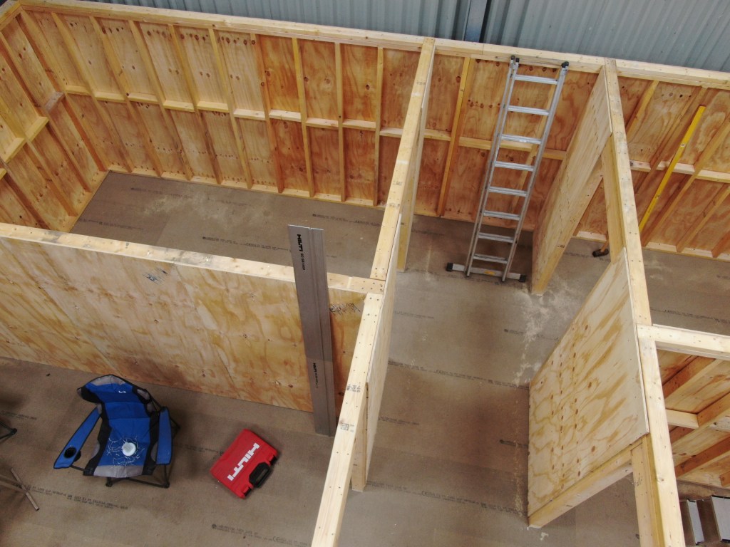
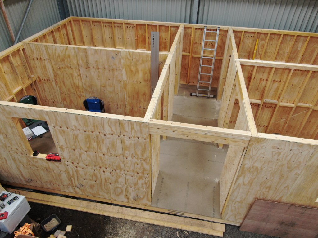
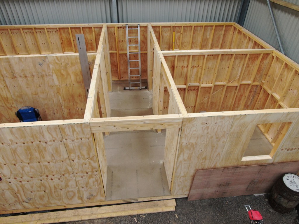
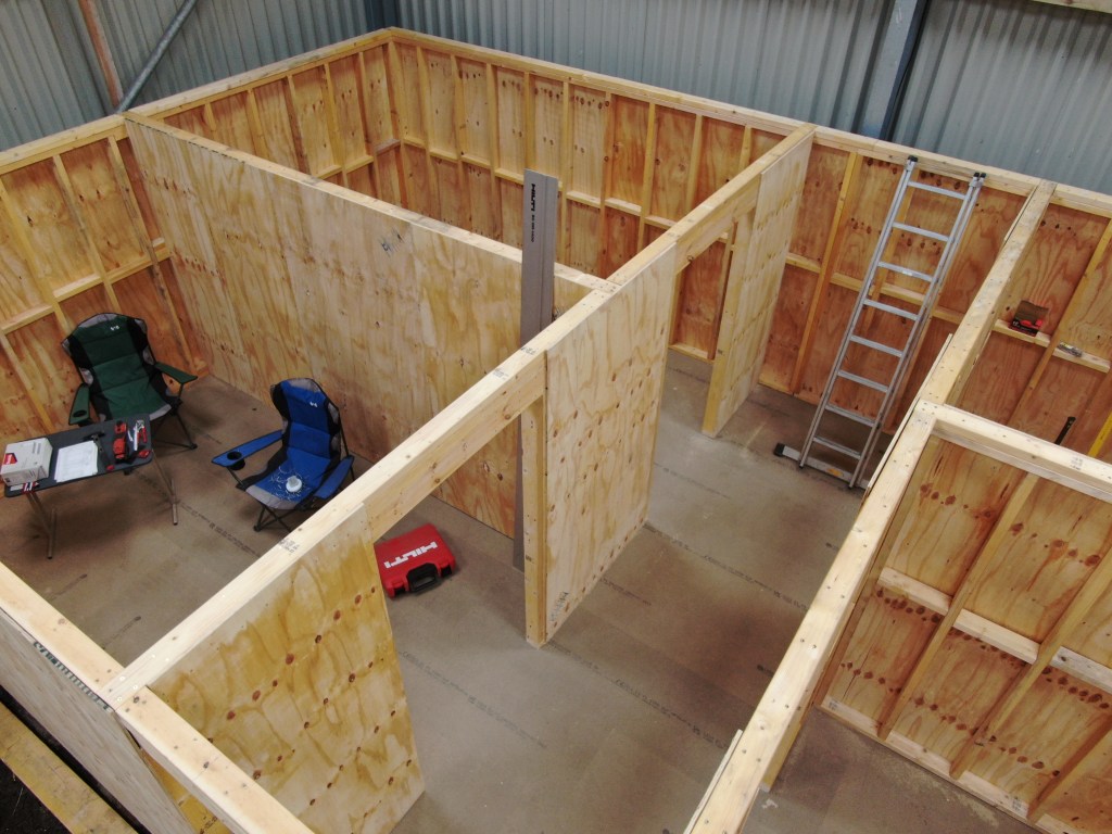
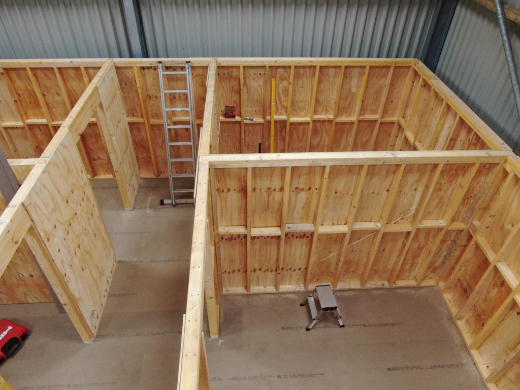
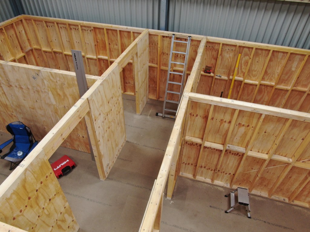
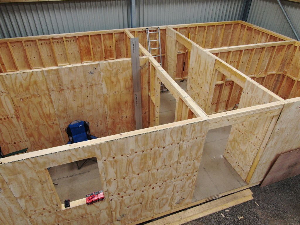
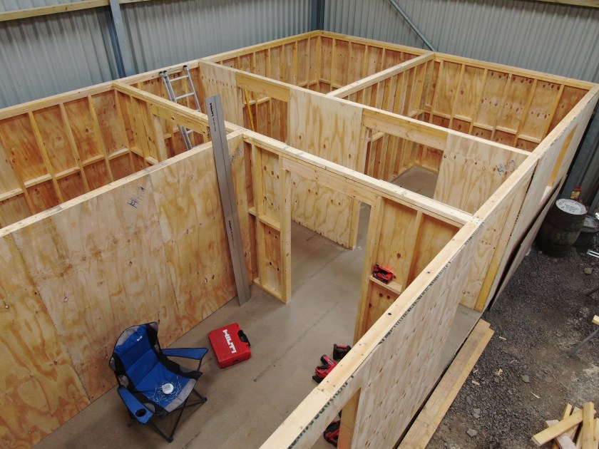
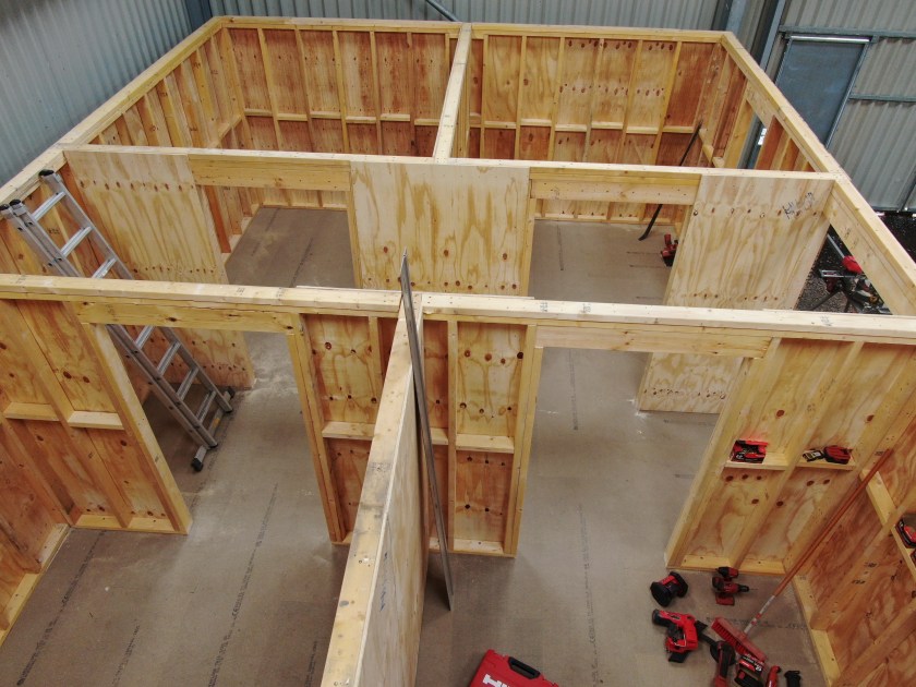
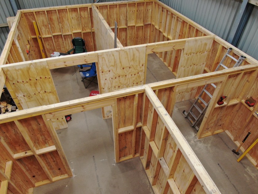
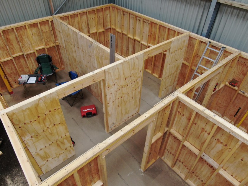
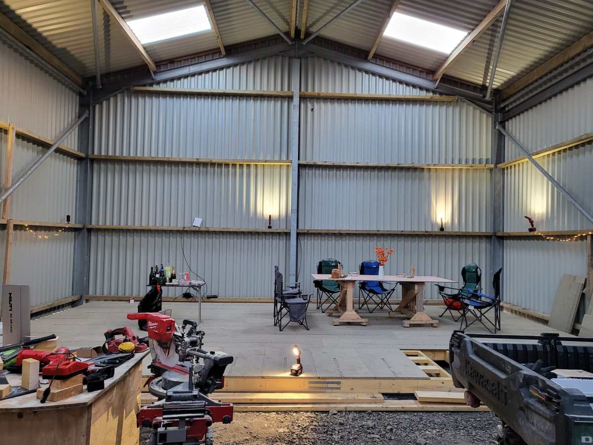
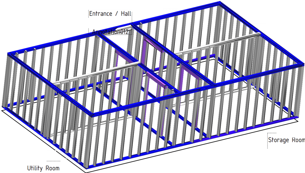
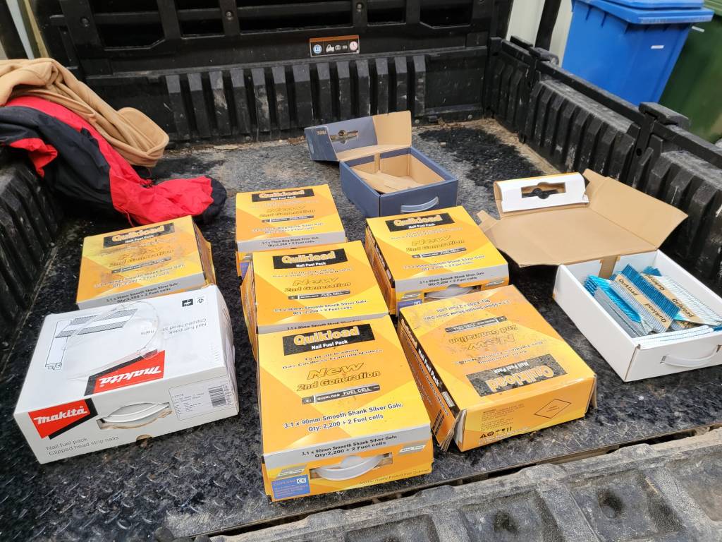
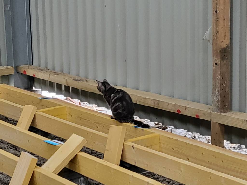
Last year in December, I started the drawings (with FreeCAD) for our “house-in-house” build: a wooden compartment inside our barn for electricity, water, storage and the like. But somehow, I never started it because of my mental concrete block (pun intended). This changed when a colleague of ours came by and helped me with laying the concrete pads. And from there we did the frame and the floor in less than 2 days – thanks to our Milwaukee Nailer and Larry Haun with his book The very efficient Carpenter.
Of course, there were some gotchas and mistakes needed to be fixed. But all in all it went really well. So well, that in fact we could have our first BBQ on the new platform (and not in the dust as usual).
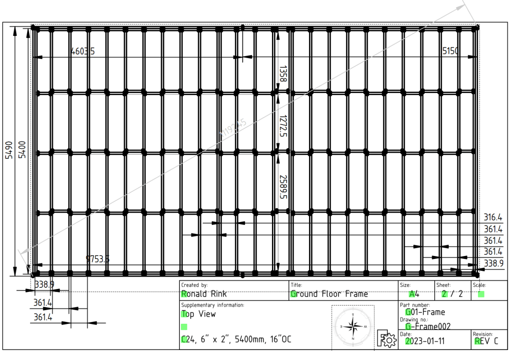
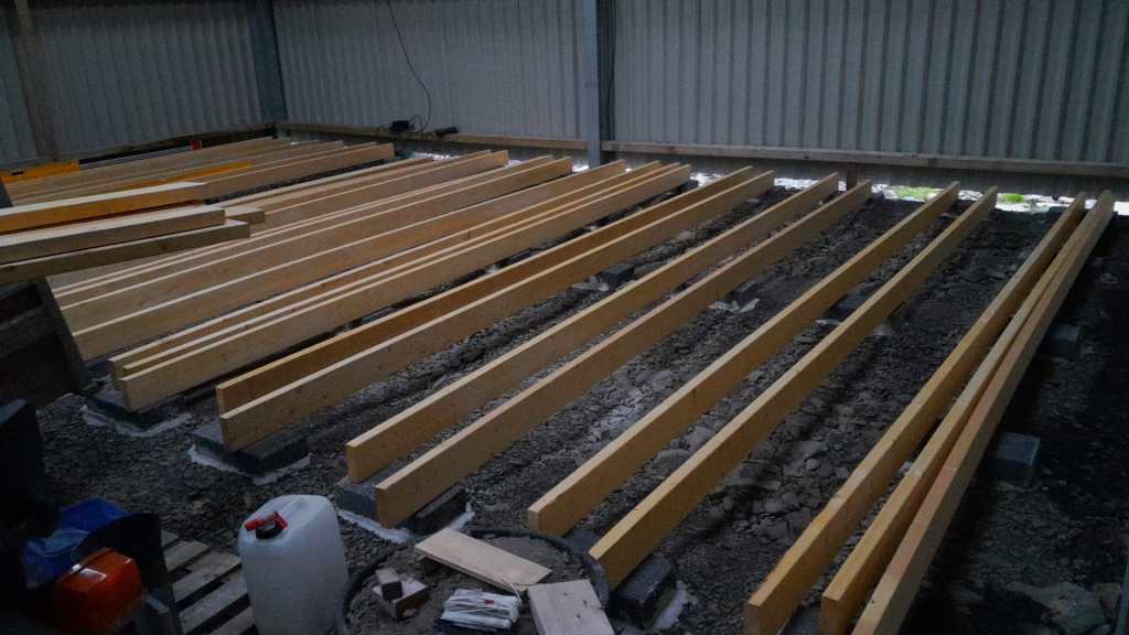
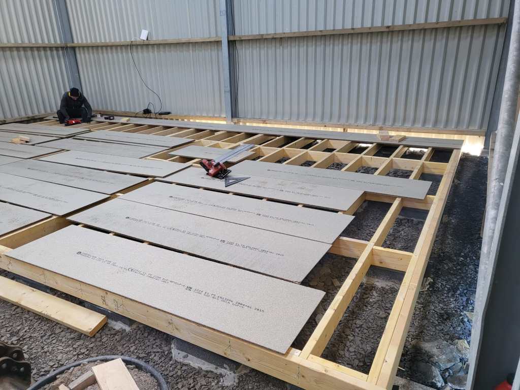
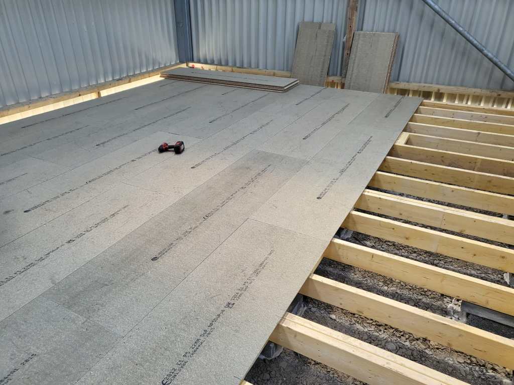
So, below you find some pictures and drawings of the “house-in-house” and the making of the platform of the ground floor.
Overview of ground floorGround floor frame resting on padsFrame of ground floor Getting the pads in placeStarting with the frameNails – the more, the betterNow only the blocks are missingInspection of our work so farThe frame is doneGround floor with the first tow of OSB sheetsGetting somewhereFinally, a table not in the dust
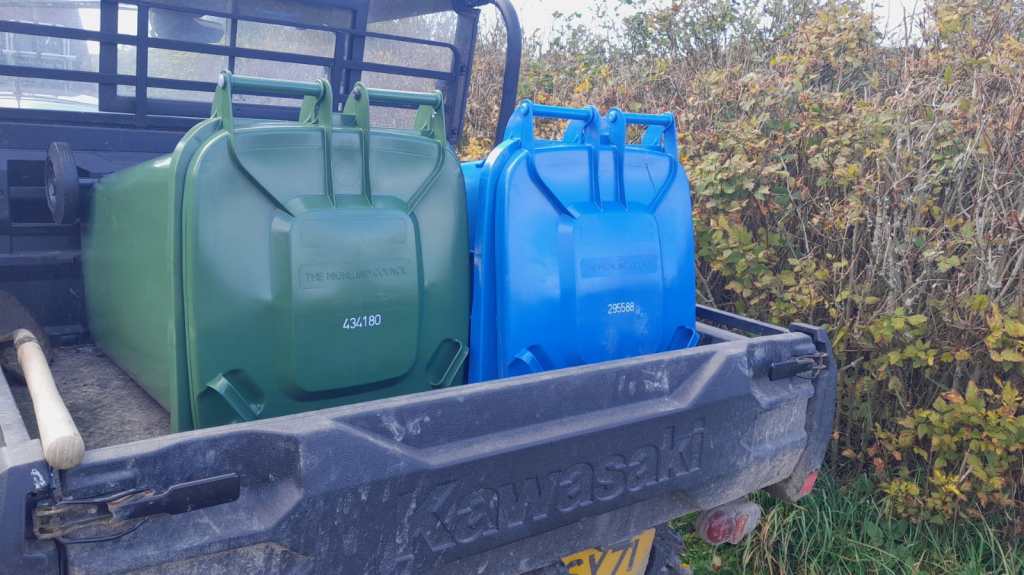
Finally, they arrived! We now have bins from the Highland Council. This means, we no longer have to drive to the Wick Recycling Centre to dipose our waste. What a convenience! For us this is another milestone (after getting a postal address, the Planning and the barn built).
Our bins delivered by the Highland Council
As our plot is not exactly reachable by the bin men we now drive them to the main road – 440m to be exact. Though this may sound tiresome, but it is still way faster than to drive to the recycling centre.
From here to there (copyright OSMaps)The path our bins take to get emptied (copyright OSMaps)
Some years ago, we bought a Autoterm 2D diesel heater with a waterproof box. This heater actually needs an external 12V power supply (or a 24V power supply, depending on the model you buy). Until now, we always connected this to one of our 12V leisure batteries. That meant we always had to carry a long 12V extension cable with us. Not any more …
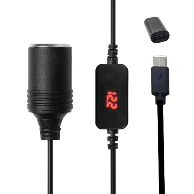
Since we had such a good experience with our mobile shower via USB-C that originally also runs on 12V, I went looking for more devices with a 3A @ 12V power requirement. And according to the data sheet Autoterm 2D just is such a device. The manual states a power requirement from 10W (min 800W heating power and 34m3/h) to 29W (max, at 1800W and 75m3/h).
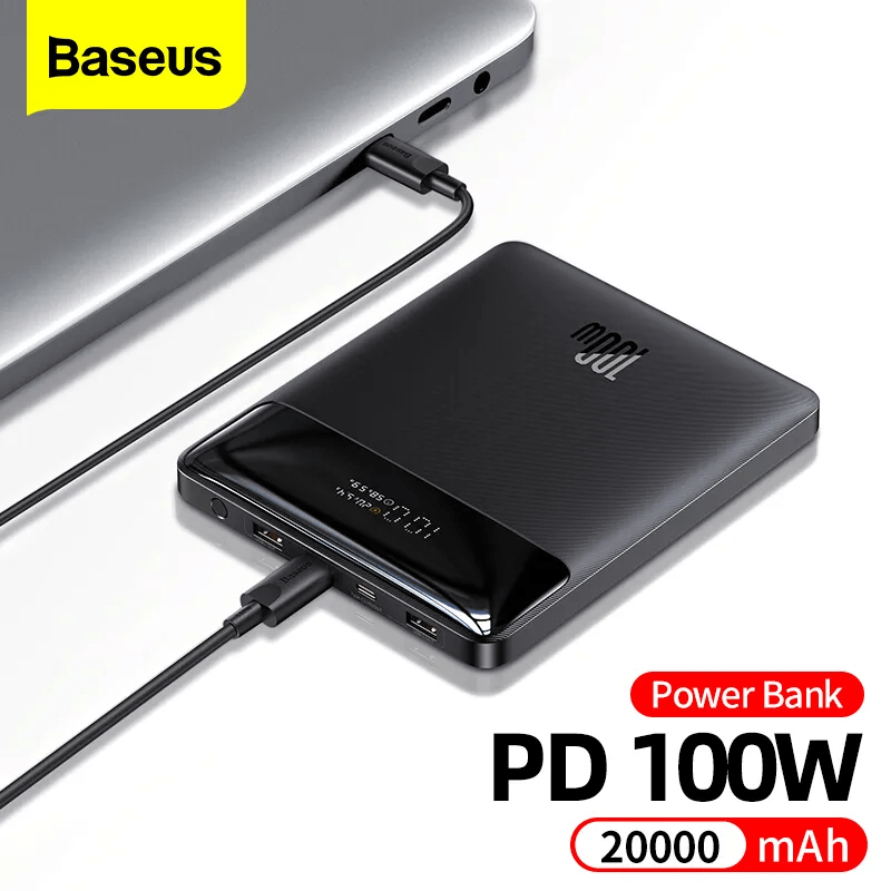
So, I got myself a Baseus 100W Power Bank 20Ah from Aliexpress that can deliver the required power. With this unit the diesel pump can be powered for approx 2.5h at full capacity and approx 7.5h at minimum capacity.
Actually, any power bank with USB-C PD that delivers 3A @ 12V could be used. And if you take a power bank with a higher capacity the heater will certainly run longer.
USB C PD Type C Male to 12V Car Cigarette Lighter Socket, taken from Aliexpress
In my opinion, the advantages of this approach are:
Flexibility: we can carry the power bank along with the heater and do not need to keep a 12V power source (leisure battery or else) nearby. An option to power a power bank is probably easier to find than a 12V source. Especially true for our trailer with a 24V battery.
Price; power bank is around 51CHF and the converter 5CHF (and the battery 1700CHF) . Compared to the other heater we have, the Profidurium Mobile-Heater 2kW, this is much cheaper. The additional battery with charger costs an additional hefty 970CHF (on top of the 2300CHF for their heater).
Weight: 400g for a power bank is a neglectable additional weight compared to a full blown battery.