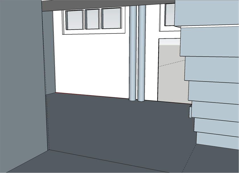
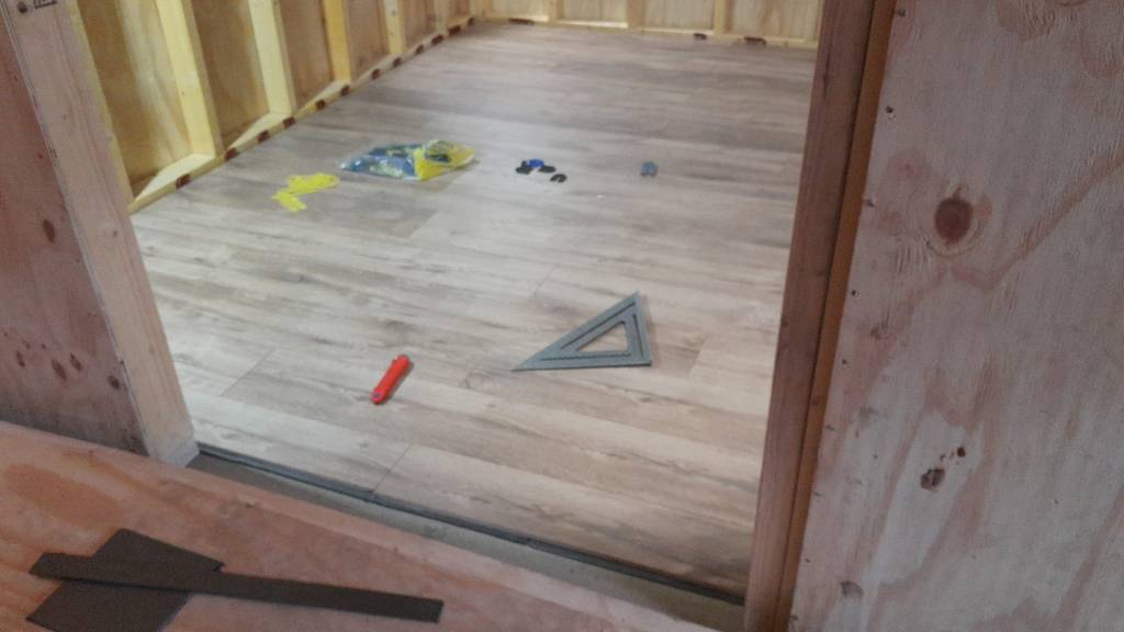
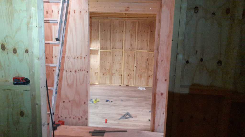
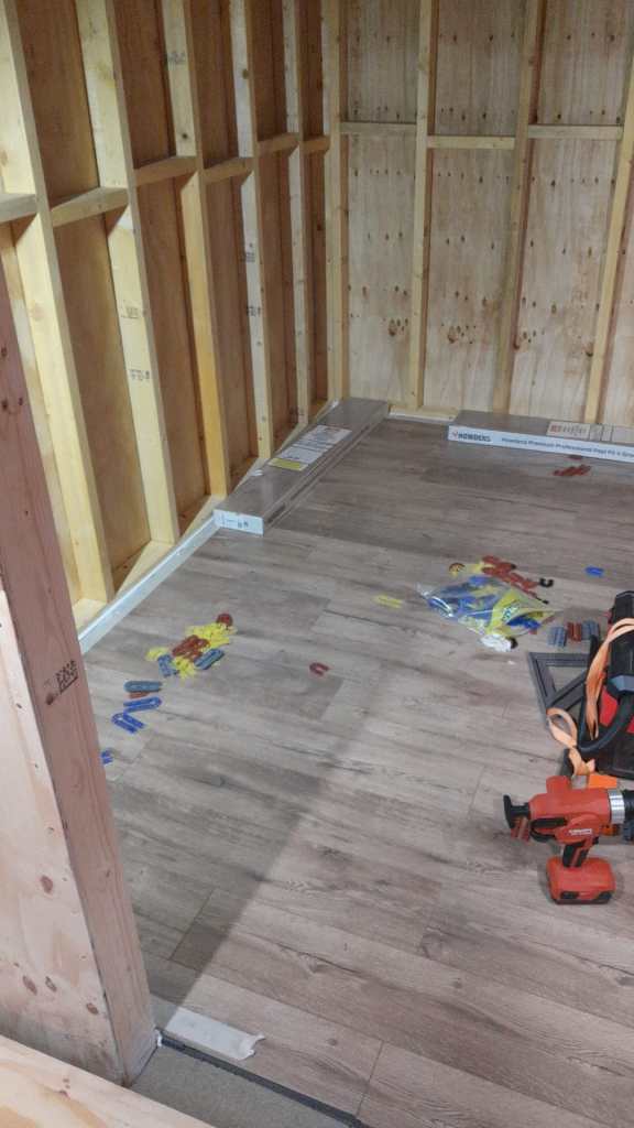
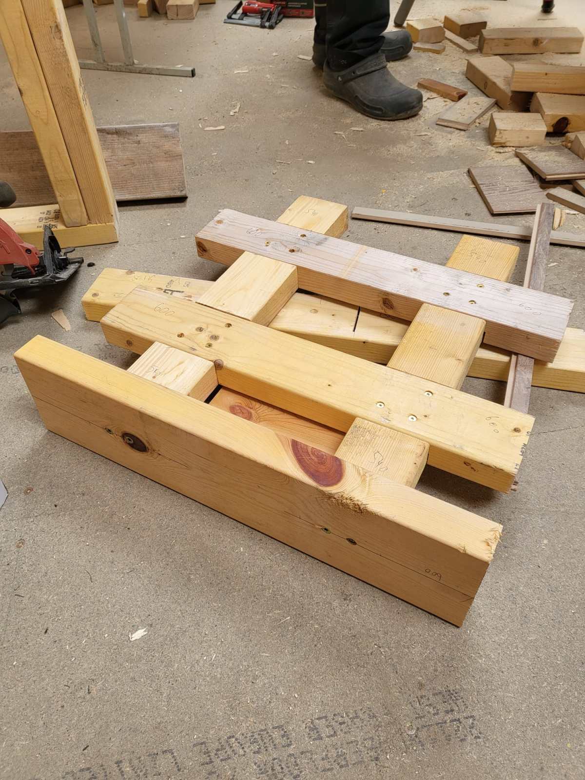
Note: this post continues our adventure of converting a workshop into a flat.
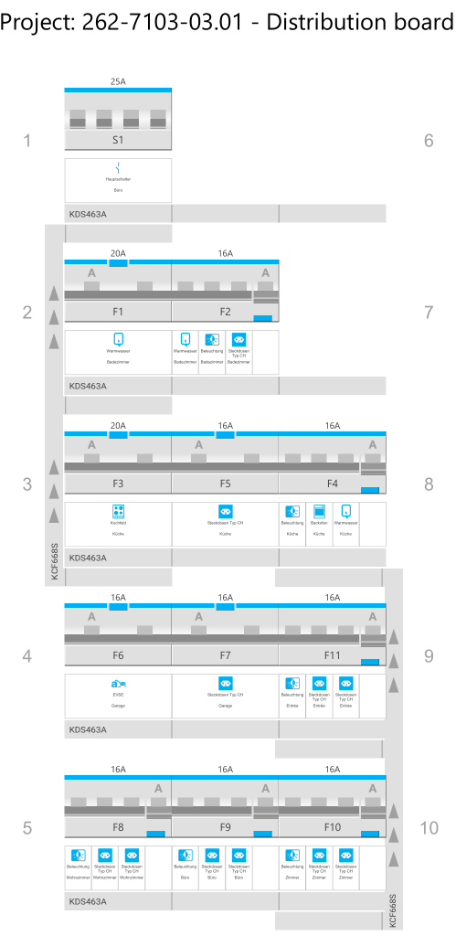
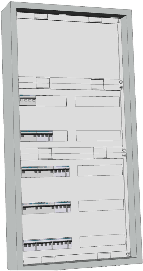
After the successful build of the terminal blocks of our distribution enclosure I continued to design a junction box for the electric wiring in the rooms.
First, I had to decide on the maximum number of connections I would expect to have in a single junction box. I came up with the number of 4. And here is why:
Most of the time, we will have a standard “Tee” to either connect sockets or to distribute to a different part of a room; and sometimes we will have a “Tee” and additionally connect a socket which will be a Feller 2xT23 Standard to which we run 5-core (3LNPE) to distribute phases. Besides, much more than 4 connections to and from the box would be difficult to achieve.
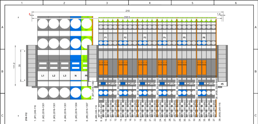
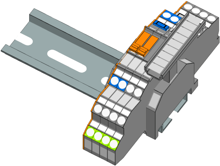
In order to facilitate testing and maintenance, I decided to equip the junction boxes with a neutral-disconnect. For this the Wago 2003-6641 comes in handy (which is much harder to get than the Wago 2003-764x models). It has a lever with a “disconnect knife” that cuts the neutral. As I want a 3LNPE 4-way junction, we have to use 2 of these next to each other with a jumper. That means, depending on what circuit we want to test, we have to remove that jumper as well.
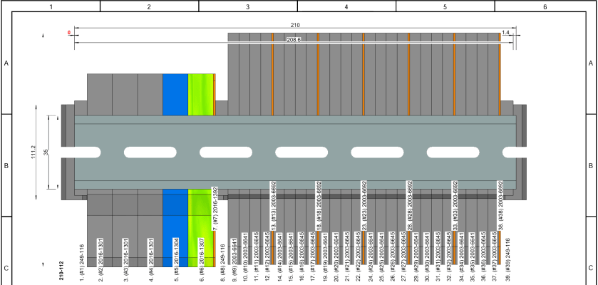
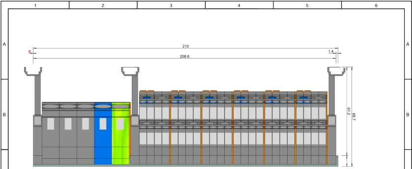
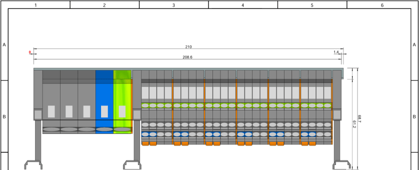
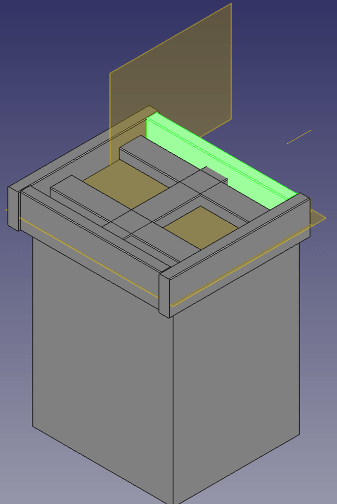
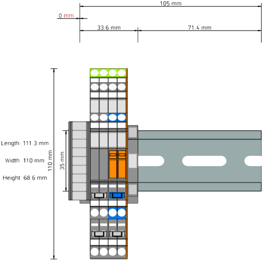
Our initial version would therefore look like this and would fit easily within 2 modules (including stop-ends):
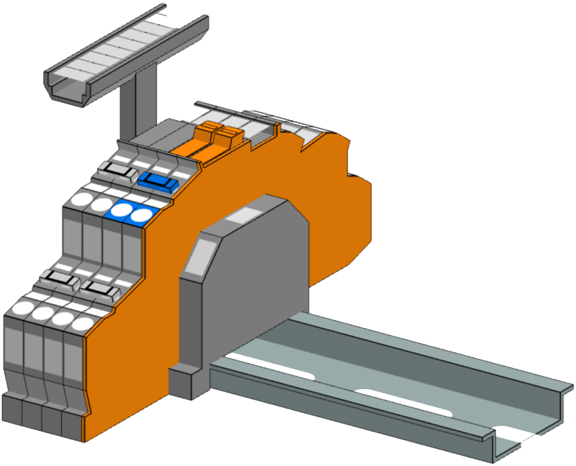
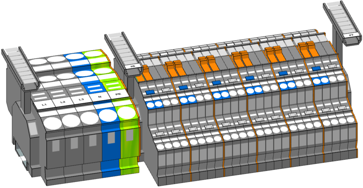
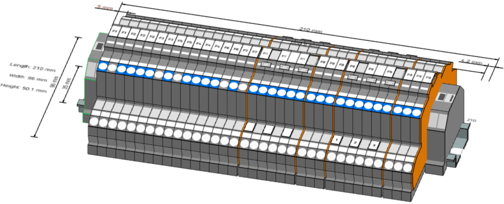
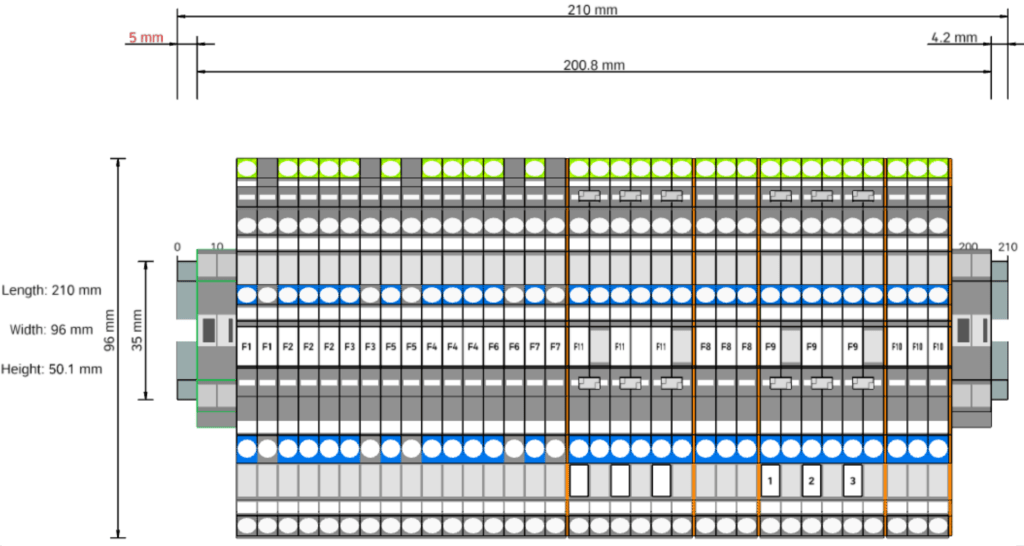
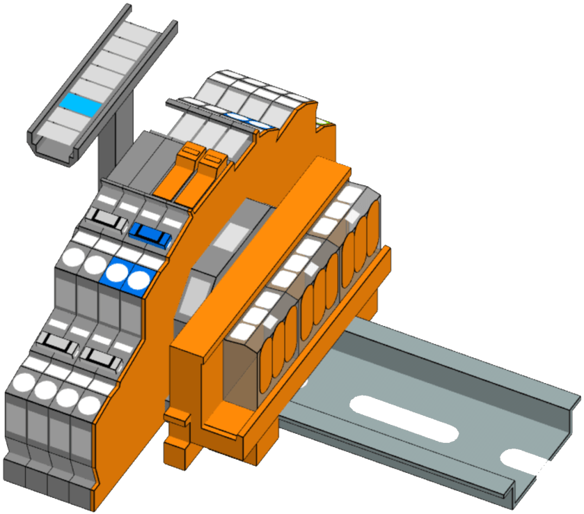
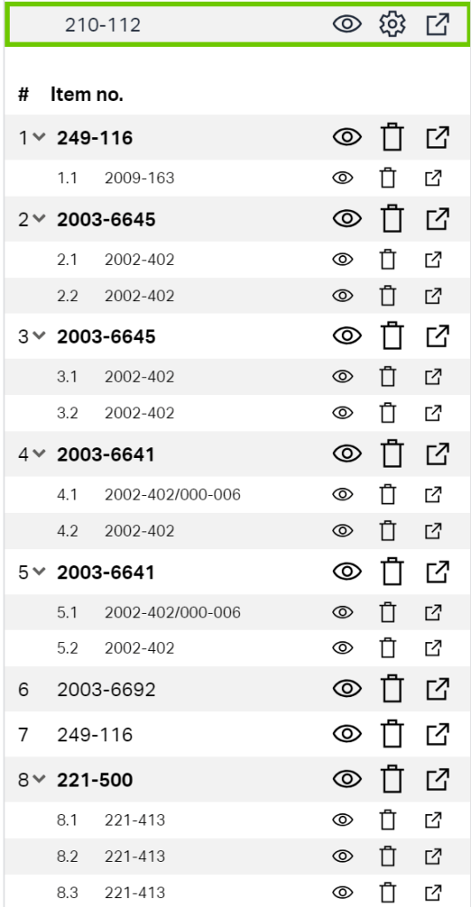
For most of our lights we want to use an Intertechno radio receiver to switch the loads. We already have some existing ITL-1000 which we will be repurposing for this conversion. However, there is also a newer version, the ITL-2000, which can switch two 1000W loads independently – which is actually the preferred way. But this means we have to split the neutral and have additional PE terminals. For this, we use the “Tested and Approved” (anyone remembering this from the 90?) Wago 221-413 connectors mounted on a mounting carrier. So, here is the final layout:


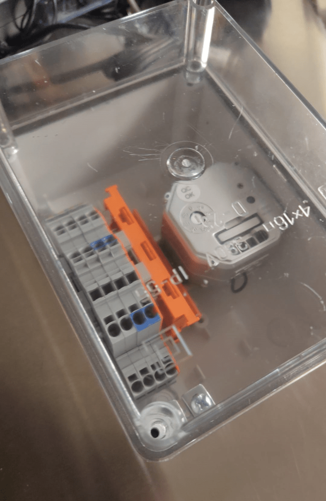
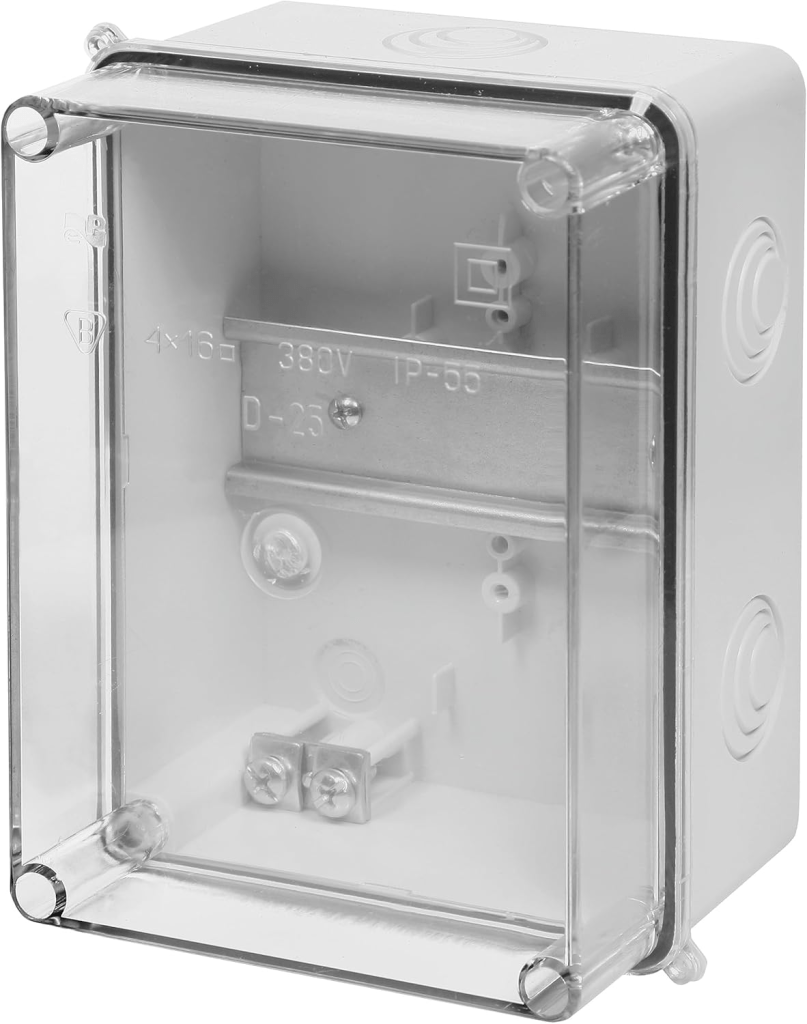
But to make this junction box look “industrial” we have to find a suitable enclosure. In my opinion it must have a transparent cover. Like this (which I found on Amazon):
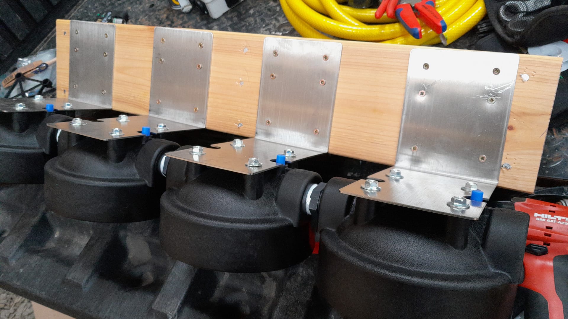
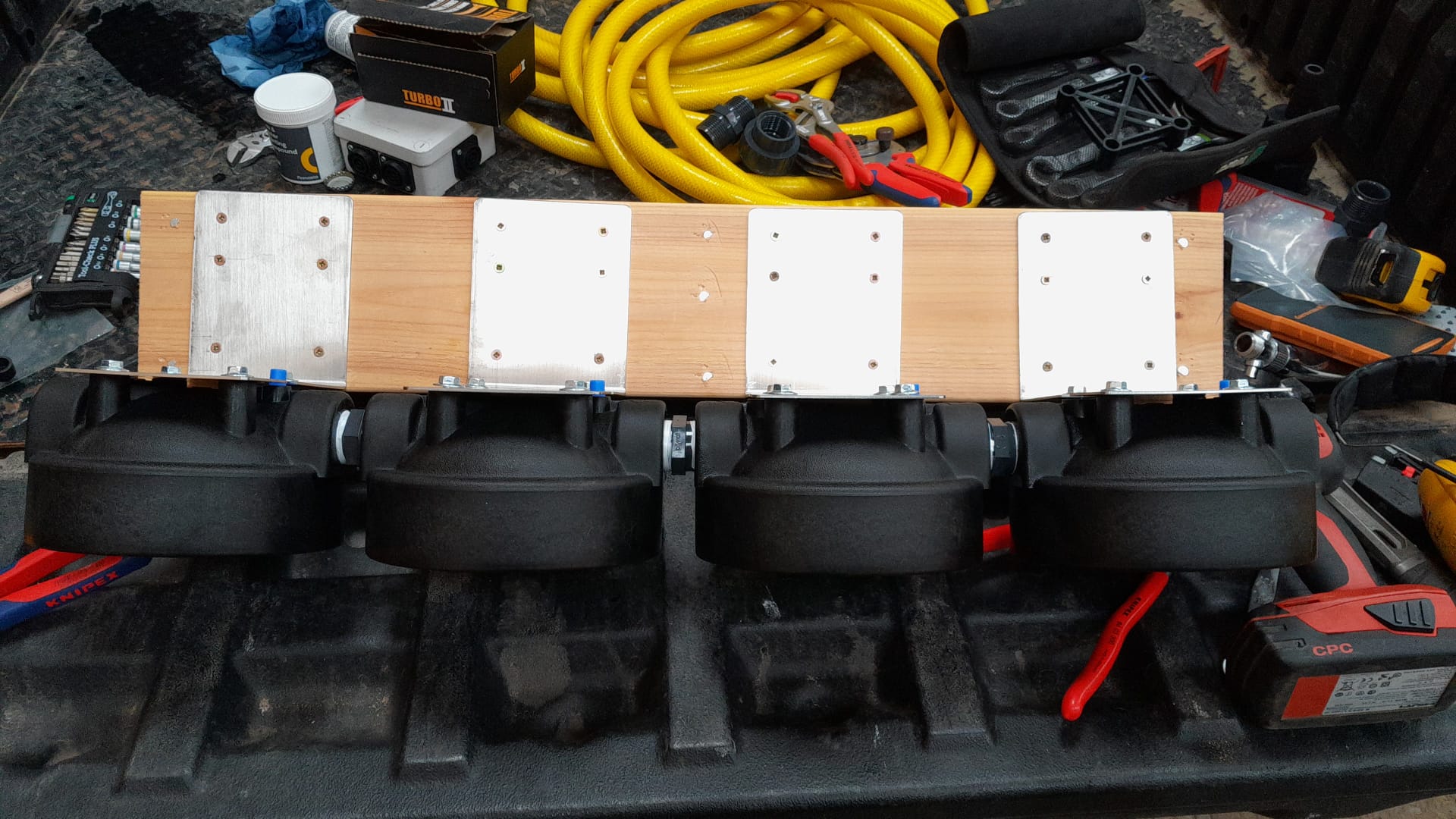
And here the box as a prototype with the terminal blocks with 2003-764x, jumpers missing and an ITL-1000 (the other parts are still in the mail). As soon as I have installed one of these on the wall with all the cabling I will post an update.