After a quick adventure with the .NET nanoFramework on microcontrollers, I sort of came back to my senses and continued with something that seemed to have a brighter future (read: more supported boards, more documentation, bigger community, …). So, after a quick look around, I tried: PlatformIO:
Sounds just too promising. At least promising enough to reactivate my C++03 knowledge and bring it up to at least C++17 (spoiler: after all there _was_ a reason why I switched to C#).
On the way I found out, that we now support auto, bool and lambda expressions but kept the splitting-of-declaration-and-implementation-nightmare – yikes …
Installation
Installation of PlatformIO was really straightforward. After the installation of VSCode, I installed the Python, C/C++ and the C++ extension beforehand. That automatically brought me CMake as well. And after that I just had to add the PlatformIO extension.
From there I could start and create my first project. And depending on the framework chosen (Arduino in my case) the main.cpp comes with either setup() and loop() or just app_main() (EspIdf).
Note: if the main file (under the src folder) is a main.c we have to rename it to main.cpp to use C++ features – I totally forgot about that …
Unit Testing
Building and flashing the controller “just worked”. So, I started to port my C# HelloWorld morse code generator to C++. Certainly, I wanted to write some unit tests along that way. And there the “trouble” started …
There is documentation, but I totally missed the way how unit testing are to be done with PlatformIO (at least when it is one with Unity:
First, unit tests are either “local” or “native” tests (on your dev machine) or “embedded” tests. We have to set up a separate *environment* for each.
The microcontroller framework (Arduino, in my case) is not supported on the native environment (not even an #include <Arduino.h> is allowed). So, we have to make sure, we use only code that is totally hardware independeent.
PlatformIO does not install a toolchain for the native environment (i.e. we have to install a C/C++ compiler ourselves). And on Windows, it is recommended to use MSYS2 with Mingw64. That effectively means, we have different compilers depending on the environment. Something, that just feels weird to me. And something that could cause problems, as I later should find out.
Every test is compiled as a separate executable with a main() function. Something I am not used to in a .NET environment. And here is again, it matters which framework (Arduino or EspIdf) we are using, as we have to repeat setup()/loop() or app_main() again and again.
The main code in the src folder is compiled as well, which leaves us with duplicate main() function. Preprocessor with #if defined() to the rescue – quite clumsy …
And then the main thing: we essentially have to move all the application code to the lib folder, as -by default- the src code is not included when unit testing. That is not only strange to me, but leaves the src folder being an empty stub, as all the code now lives in the the (private) lib folder.
Documentation or the Calculator example were only partially helpful. I ended up with the weirdest compilation and linker errors I never dared to imagine.
Unity requires we need to specify all tests manually if we want to run them.
But in the end, I got it working. Here is what I did:
Guard your src/main.cpp with #if defined(ARDUINO) / #endif.
Move everything else to lib (hardware / framework dependent and indepedent code).
My first impression is … mixed. On the one hand, PlatformIO makes it relatively easy to develop for different hardware/boards. Due to VSCode the “developer experience” is much better than with the Arduino IDE.
But … setting up Unit Testing and how it is implemented is rather awkward. Needless to say, that error messages are not for the faint of the heart.
I cannot say, that I miss my C++ days. On the other hand, not something I could not get used to and around with it.
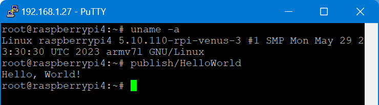
Today, I tried to run a C# console application on a Venus OS – and it pretty much worked right away. But why would I want to do that?
The answer is simple: a couple of weeks ago I started to add some “drivers” to Venus OS to support additional features like using a MultiPlus-II as a charger for top balancing cells. With Venus OS, most of the examples I found were written in Python (except for some C++ extensions). And it is no secret that I am not too fond of that. So, why not using my favourite programming language on Venus OS as well?
My first thought was, I would have to install the .Net framework on Venus OS. But, with the advent of self-contained (and thus framework-independent) executables this is not needed.
linux-arm was needed, as Venus OS is a 32-bit operating system (regardless of the 64bit architecture of the Pi 400). I chose PublishTrimmed to save some space. And of cource, --sc for self-contained.
I then gzipped the publish folder and copied it to the Venus OS (via WinSCP). After uncompressing the files (with permissions left intact), I ran the program and got this error:
Process terminated. Couldn't find a valid ICU package installed on the system. Please install libicu (or icu-libs) using your package manager and try again. Alternatively you can set the configuration flag System.Globalization.Invariant to true if you want to run with no globalization support. Please see https://aka.ms/dotnet-missing-libicu for more information.
Enabling invariant mode seemed to be the easier choice. After all, my future drivers would hopefully not need globalisation support anyway. So, I recompiled after adjusting the .csproj file:
I executed this on a Raspberry Pi 400 running Venus OS v3.00 and .Net 7.
From there, I wanted to connect to D-Bus which proved to be more difficult. Following the Connecting .NET Core to D-Bus I had to find out that Tmds.DBus.Tool was not compatible with .Net 7. I will have to look into that separately.
Note about IL trimming: the size difference is really noticable. In my example the untrimmed compilation was around 65MB and the trimmed version around 13MB. However, it seemed to me that the trimmed version took slightly longer to load and execute. So, I am not sure if I will keep this switch on.
So, what would be the perceived advantages of using .Net on Venus OS for me?
Known developing environment
Better type safety
Reusability of a lot of basic code
Easier testing and mocking
But this is only my personal opinion and preference. Yours might differ.
When setting up a Raspberry Pi to run Venus OS, the GUI is not available on the local HDMI port – it is running headless by default. However, in order to connect to a Wireless network, we need to access that UI.
As mentioned in the above link, there is a workaround to it: renaming (or removing) the /etc/venus/headless file. This can be done by connecting via the serial port to the PI using the Adafruit USB to TTL serial cable. There is a very thorough article on how to connect to the port.
In short, pin 8 (GPIO14, TX) is white; pin 10 (GPIO15, RX) is green and pin 6 can be used as ground (black) and DO NOT USE the red wire. See here for the actual Pin layout. We can then use Putty to make a connection to the Pi (at 115200bps).
So far, so good. However, when trying to rename the headless file the following error message appears: mv: can't rename 'headless': Read-only file system
Connecting to Wi-Fi with via Bluetooth and Victron Connect
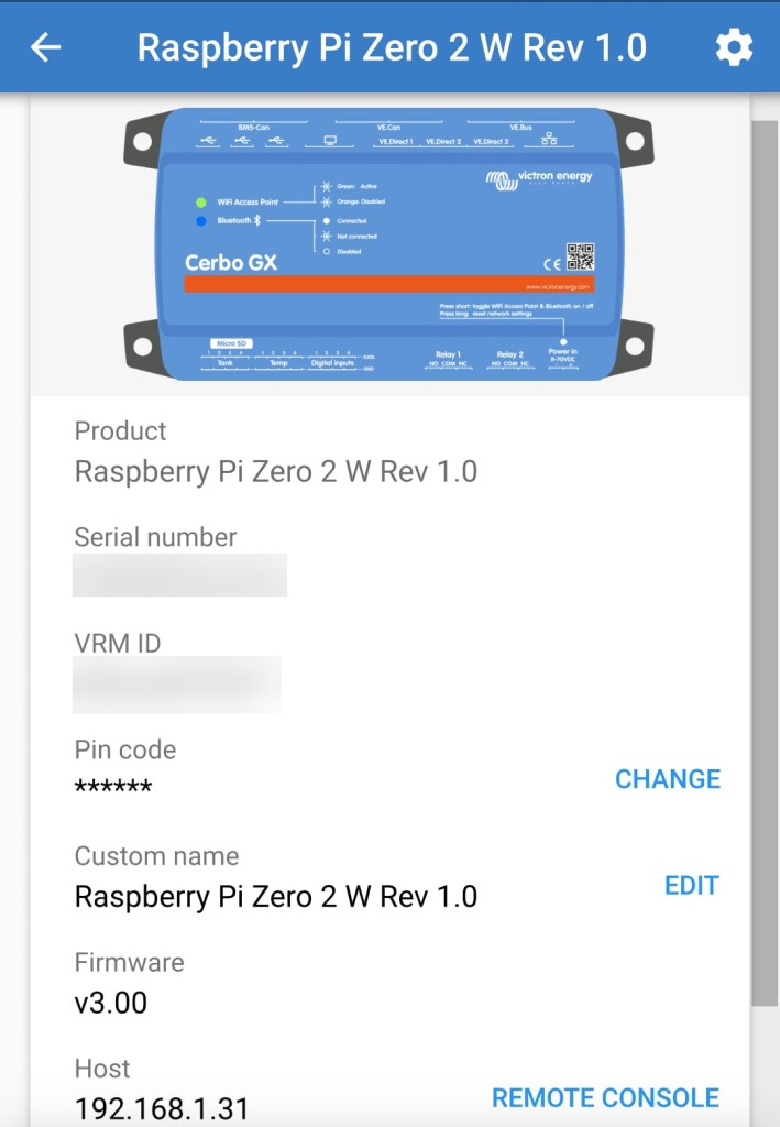
In case you only want to connect to Wi-Fi and do not happen to have a serial cable, but you want to use the Raspberry Pi’s bluetooth connection, you can use Victron Connect to configure wireless network settings.
For this you start up Victron Connect on an Android (or Apple i device, Windows will nork work for that) and discover the Raspberry you want to connect. When pairing with the Pi use 000000 as the pin code.
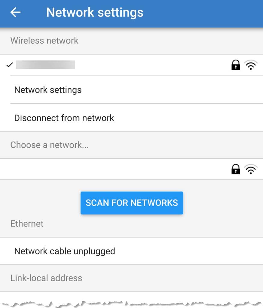
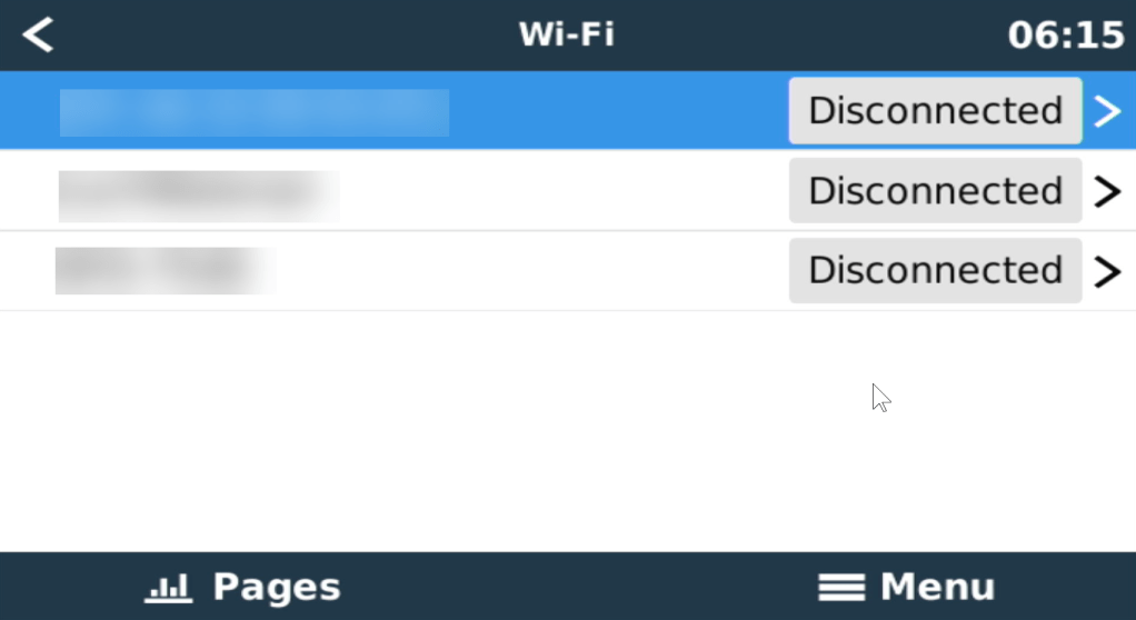
After that you will find the gear icon in the upper right corner. From there you can select Network settings and connect to your WLAN.
Below you find some screenshots.
Bluetooth connection to Venus OS via Victron ConnectConfigure Network settingsConnecting to a WLAN
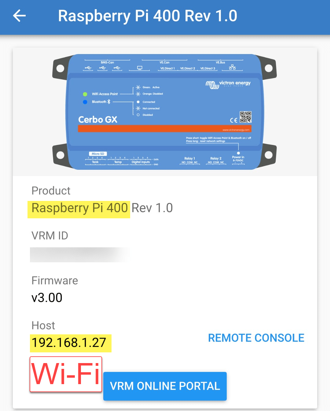
When we run Venus OS without any modifications on a Raspberry Pi 400 no WiFi is detected – though the Pi 400 certainly has WiFi onboard.
As it seems, I am not the first one to notice that. bipedalprimate presented a solution by copying a bunch of Raspbian /lib/firmware files to the Venus OS. But as it turns out, things can be achieved much simpler.
It seems, that the driver on the 400 is differs from the chipset of a _regular_ Pi 4: it is the brcmfmac43456.
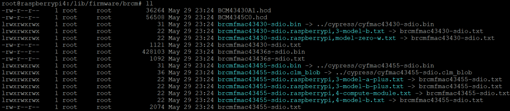
When looking at the /lib/firmware/brcm folder of a Venus OS these drivers are missing:
Venus OS v3.00 contents of /lib/firmware/brcm
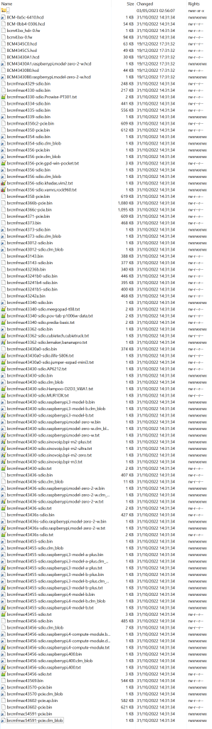
On a Raspberry Pi 400 things look different:
Raspberry Pi 400 Raspbian 6.1.21 contents of /lib/firmware/brcm
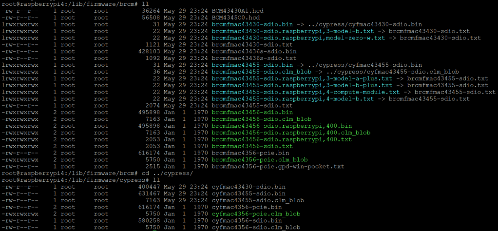
As it seems, only a few files are required for a Raspberry Pi 400 and only a few belong to the brcmfmac43456. Most of the files are in fact links to other files (and some are in the cypress directory).
So, I did the following: I copied the brcm and cypress directories to a USB stick and inserted it into the Pi 400. From there I copied the driver files to the respective directories inside /lib/firmware, added some links and adjusted the permissions. Below you see the commands I used.
Note1: I am a novice when it comes to Linux, so pls do not expect any sophisticated shell scripting.
Note2: by default the root file system is _read-only_. Therefore I re-mounted it as read-write (so, maybe our changes will not survive a firmware update).
Note3: my USB stick was mounted as /run/media/sda1. Yours might be different.
This file contains hidden or bidirectional Unicode text that may be interpreted or compiled differently than what appears below. To review, open the file in an editor that reveals hidden Unicode characters.
Learn more about bidirectional Unicode characters
In our trailers and vehicles I prefer 24V 8s batteries, as the price-weight-power triangle of our Eve 280Ah cells is hard to match. With a gross weight of roughly 55kg we get a nominal “capacity” of 7168Wh. Even at a low cell voltage of 2.7V we can still get more than 2400W (3000VA) out of the battery. Exactly what a Victron MultiPlus-II 24/3000/70-32 (or any 3000VA inverter/charger for that matter) can deliver.
The Honda EU 10i has a sustained output of 900W which equates to roughly 3.9A at 230V. Now, this is not too interesting by itself.
However, the minimum AC current input of the MultiPlus is 3.6A. So, exactly within the range of the Honda EU 10i. A 5000VA inverter for example, would drain the generator with its minimum input of 4.6A+. And with its fuel tank capacity of 2.1l it runs nearly 4h on full load. Which in turn means, I can charge our 24V 8s battery about 50% without refueling.
Note: ideally we would charge it from 25% up to 75% SoC.
So, for me this generator is the ideal backup when I am away without any EV station nearby. With its 13kg and small form factor (and price) there is always a place in my vehicles where I can put it.
And as a side benefit: when I run the generator along with the inverter I can generate up to 3300W (or over 14A). That is: run my oven and boil potatoes at the same time …
And the generator even makes sense when combined with a Victron MultiPlus Compact 24/1600/40-16 (or its 12V counterpart). They are the smallest inverters/chargers in that power range. They strong enough to run a coffee machine or immersion water heater, but are not pwoerful enough to run a full 2000W appliance. However, in combination with the Honda, they just reach 2180W. Of course, charging a 24V 8s battery with a “Compact” device takes much longer, due to its smaller charger.
Along with some others I am waiting for Raspberry PIs to become available again (while *not* supporting these overpriced resellers on eBay, Amazon and elsewhere).
Luckily, back in 2016 (or was it 2015?) I bought two Raspberry PI2 Model B Rev. 1.1 with 1 GB RAM and an Edimax EW-7811Un WLAN adapter. At that time the PI did not have built-in WLAN and it was said that the original Wifi dongle Raspberry Pi WLU6331 did not work with all distributions.
We had some plans what to do with the Pi – but they never made it into reality. Instead, they went into the locker.
Edimax EW-7811Un WLAN adapter
Fast forward into the future, the whole world experiences stock supply shortages and a Raspberry Pi (now in its 4th generation) is hard to get hold of.
As I am building a couple of batteries mostly with JK-BMS I need a RS-485 connection to my Victron inverters to control charge and discharge currents. Except for the GX versions of the MultiPlus-II and EasySolar-II that _sort of_ support RS-485 (not out-of-the-box, but) in a single box, I always need an additional device like a Cerbo, BBB or: a Raspberry Pi!
But as I already wrote: I did not want to support resellers with their pharmacy pricing, so I had a look at the Venus OS compatibility list and saw that – surprisingly – even a Pi 2 is supported. So, I went looking in my shelves, lockers and other places to find these rusty old Pi 2s – and after a couple of weeks I actually found them (when I was looking for something completely different). Anyway, here they are – but only with a single GB of RAM.
Nostalgic side note: yes, there were times where I would have left out the word “only” …
I was not to sure if Venus OS would run on it. And if – how quick. It was time to find out …
Installation was straight forward: following Getting Started was all it needed. I connected the Pi to my local wired network for that purpose and makes updating and installing software much easier. At the very start I also enabled superuser and SSH access.
Note: There was a minor issue or whatever one might call it. After the install of v3.00 (via the SD card) I had the device check for an update (which at that time should not have been available). But for whatever reason, I was offered to update from v3.00 to v3.00. I did that and it worked and after that no more updates were recommended.
From then on, installing additional packages worked without an issue – but took considerably longer than on a Cerbo, Pi 4 or even the GX in the EasySolar.
One thing just seemed to be missing. Having the Pi to act as a Wifi access point (and router with DNS and DHCP). Why would I want this?
Some of my batteries are just standalone installations in a car, trailer or other machinery. And external network is not always available. And I do appreciate the comfort of wirelessly connecting to the GX – just as I am used to when using my EasySolar-II GX.
And as nearly always: I was not the first one to ask for such a feature:
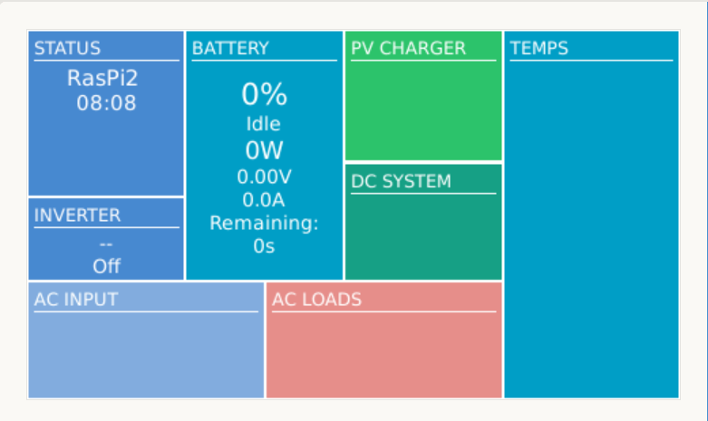
After a reboot, I could successfully connect to the access point and VictronConnect immediately found the “Cerbo”:
Raspberry Pi 2 Model B Rev. 1.1 as a Victron GX device while acting as an access point
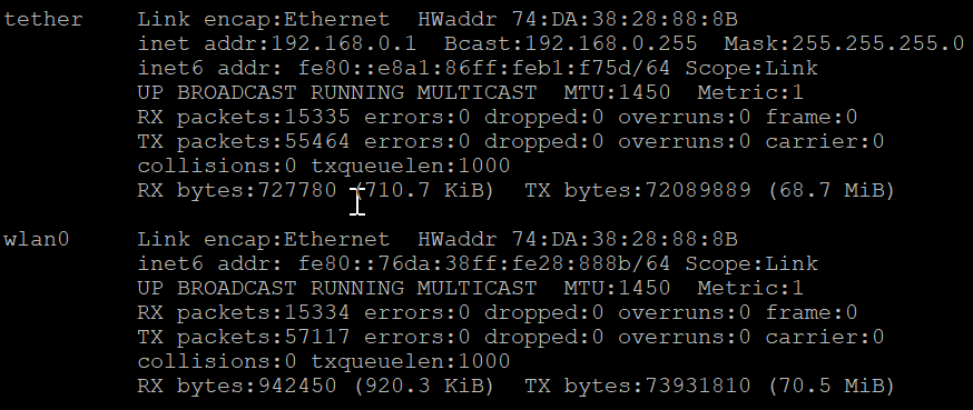
After I enabled the access point (or tether option) I could no longer see or access any other SSIDs from the Pi:
WLAN client is deactivated when running an access point
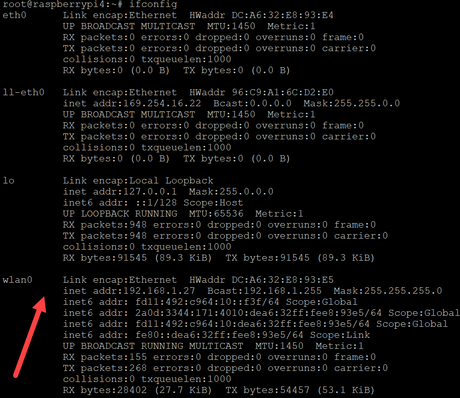
Running ifconfig gave me this output:
ifconfig output after enabling the access point
Certainly, I was interested in the performance or resource consumption of the Pi 2. As it turned out, the UI really took some CPU but the additional network services themselves were not quite as hungry: idle floats between 71% and 92%.
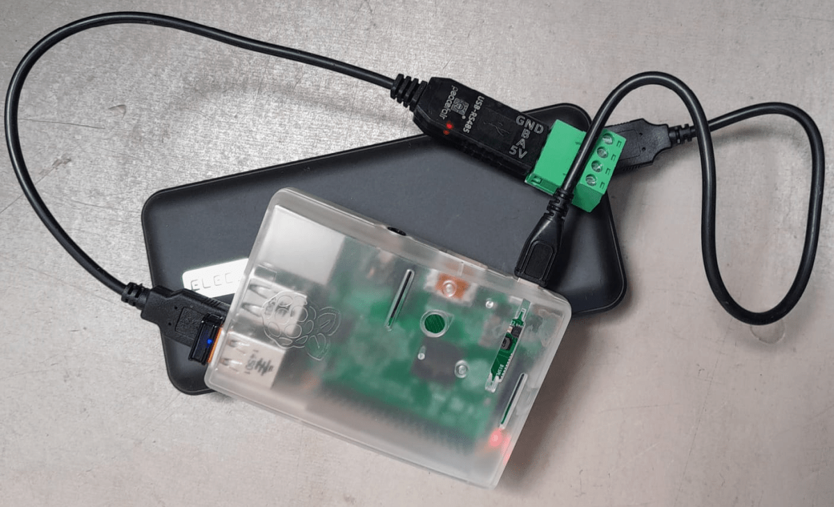
Pi 2 running with a RS-485 adapter and enabled access point
So, this is it. My investment of roughly 35$ in 2016 (even with intereste rate) really paid off. I have a working GX device that does everything I want – plus an access point – all in a single box.
Pi 2 running with dbus-serialbattery, BatteryAggregator and access point
Top balancing is a topic where a lot of people have written about – and now it is my turn …
It is common understanding to use a regular charger when top balancing, and one the one hand set the Charge Voltage Limit (CVL) to cellCount * 3.65V and use a reasonable current and wait for an extended period of time until all cells have reached their cell voltage maximum. And reasonable means to use a current where the BMS balancer keep up with and distribute the Amps across the cells without going into a Overvoltage (OVP) for a single cell.
So, instead of using a charger with a high supported current of at least 20A we now can use our regular Victron MultiPlus-II inverter/charger – with the help of Venus OS.
The reason why we cannot use a Victron MultiPlus-II out of the box as a charger is the fact, that is does not support fixed Amp configurations (only maximums). And after a while at a specific voltage the MultiPlus-II would enter Absorption phase and thereby reducing the current over time and stopp charging after a while altogether.
So with the help of a custom service (or Python script based on the dummyservice) we can create a battery monitor and set a fixed current.
I am not going into details on how to get a Venus OS device (Victron Cerbo GX or Raspberry Pi) up and running. There is plenty of information on the internet. Or have a look at this article where I briefly describe the setup of a Pi for our BYD battery system.
The *service* itself can be run from a shell: /data/VirtualBatteryMonitor/VirtualBatteryMonitor.py (I copied the script into /data to survive a firmware update).
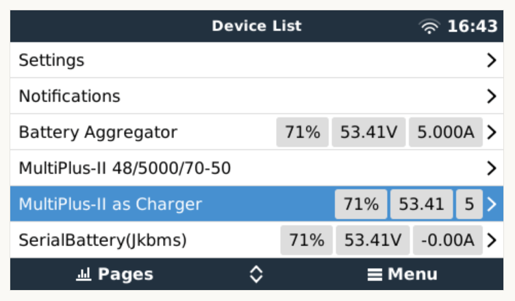
And then the service should appear in the “Device List”:
Our service as a device to support a constant charge current
There are two more configuration entries needed:
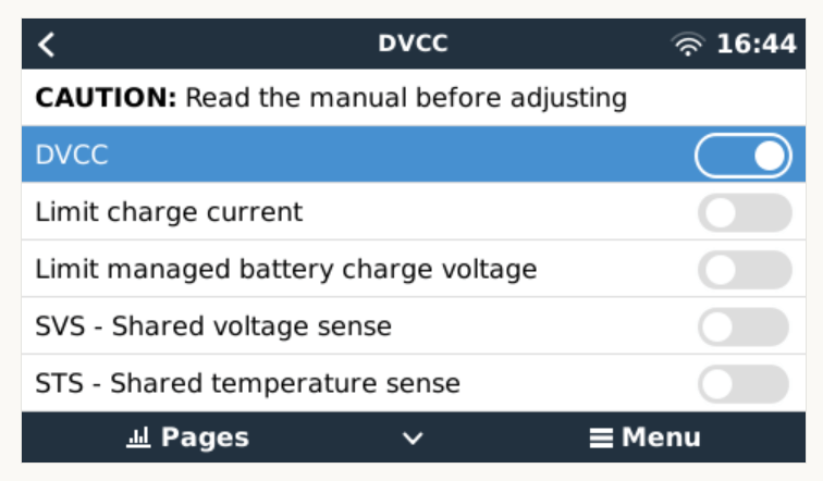
Enable our service as “Battery Monitor” (Settings, System setup, Battery Monitor)
Our service configured as a “Battery Monitor”Enable DVCC
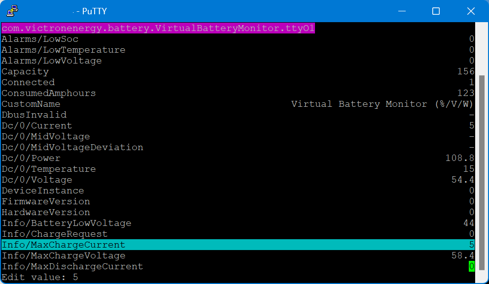
The actual parameters (charge current and maximum voltage) can be configured via dbus-spy from a shell:
Service parameters as shown by dbus-spy
The actually configured values are then shown under “Parameters” of the service (Service, Parameters):
Current configuration set to 5A constant charge current
Note1: There is no need for an actual integration of the BMS with the Venus OS.
Note2: Use at your own risk. Misconfiguring could potentionally harm the BMS, the battery or both.
Note3: Do not leave the script running / the battery charging unattendedly.
#!/usr/bin/env python3

"""
A class to put a simple service on the dbus, according to victron standards, with constantly updating
paths. See example usage below. It is used to generate dummy data for other processes that rely on the
dbus. See files in dbus_vebus_to_pvinverter/test and dbus_vrm/test for other usage examples.

To change a value while testing, without stopping your dummy script and changing its initial value, write
to the dummy data via the dbus. See example.

https://github.com/victronenergy/dbus_vebus_to_pvinverter/tree/master/test
"""
from gi.repository import GLib
import platform
import argparse
import logging
import sys
import os
import dbus
import os

# our own packages
sys.path.insert(1, os.path.join(os.path.dirname(__file__), "../ext/velib_python"))
sys.path.insert(1, "/opt/victronenergy/dbus-systemcalc-py/ext/velib_python")
from vedbus import VeDbusService
from vedbus import VeDbusItemImport

class VirtualBatteryMonitor(object):
    def __init__(
        self,
        servicename,
        deviceinstance,
        paths,
        productname="MultiPlus Charger",
        connection="dbus",
    ):

        try:
            # Connect to the sessionbus. Note that on ccgx we use systembus instead.
            logging.debug("Opening SystemBus ...")
            dbusConn = dbus.SystemBus()
            logging.info("Opening SystemBus SUCCEEDED.")
        except:
            logging.error("Reading system SOC FAILED.")

        logging.debug("Opening dbus '%s' ...", servicename)
        self._dbusservice = VeDbusService(servicename)
        logging.info("Opening dbus '%s' SUCCEEDED.", servicename)
        self._paths = paths

        logging.debug("%s /DeviceInstance = %d" % (servicename, deviceinstance))

        # Create the management objects, as specified in the ccgx dbus-api document
        self._dbusservice.add_path("/Mgmt/ProcessName", __file__)
        self._dbusservice.add_path("/Mgmt/ProcessVersion", "Unkown version, and running on Python " + platform.python_version())
        self._dbusservice.add_path("/Mgmt/Connection", connection)

        # Create the mandatory objects
        self._dbusservice.add_path("/DeviceInstance", deviceinstance)
        self._dbusservice.add_path("/ProductId", 0)
        self._dbusservice.add_path("/ProductName", productname)
        self._dbusservice.add_path("/FirmwareVersion", 0)
        self._dbusservice.add_path("/HardwareVersion", 0)
        self._dbusservice.add_path("/Connected", 1)

        # Create all the objects that we want to export to the dbus
        self._dbusservice.add_path('/Dc/0/Voltage', 3.4 * 16, writeable=True)
        self._dbusservice.add_path('/Dc/0/Current', 5, writeable=True)
        self._dbusservice.add_path('/Dc/0/Power', 3.4 * 16 * 2, writeable=True)
        self._dbusservice.add_path('/Dc/0/Temperature', 15, writeable=True)
        self._dbusservice.add_path('/Dc/0/MidVoltage', None)
        self._dbusservice.add_path('/Dc/0/MidVoltageDeviation', None)
        self._dbusservice.add_path('/ConsumedAmphours', 123, writeable=True)
        self._dbusservice.add_path('/Soc', 75, writeable=True)
        self._dbusservice.add_path('/TimeToGo', None)
        self._dbusservice.add_path('/Info/MaxChargeCurrent', 5, writeable=True)
        self._dbusservice.add_path('/Info/MaxDischargeCurrent', 0, writeable=True)
        self._dbusservice.add_path('/Info/MaxChargeVoltage', 3.65 * 16, writeable=True)

        self._dbusservice.add_path('/Info/BatteryLowVoltage', 2.75 * 16, writeable=True)
        self._dbusservice.add_path('/Info/ChargeRequest', False, writeable=True)
        self._dbusservice.add_path('/Alarms/LowVoltage', 0, writeable=True)
        self._dbusservice.add_path('/Alarms/HighVoltage', 0, writeable=True)
        self._dbusservice.add_path('/Alarms/LowSoc', 0, writeable=True)
        self._dbusservice.add_path('/Alarms/HighCurrent', 0, writeable=True)
        self._dbusservice.add_path('/Alarms/LowCellVoltage', 0, writeable=True)
        self._dbusservice.add_path('/Alarms/LowTemperature', 0, writeable=True)
        self._dbusservice.add_path('/Alarms/HighTemperature', 0, writeable=True)

        self._dbusservice.add_path('/Capacity', 156, writeable=True)
        self._dbusservice.add_path('/CustomName', "Virtual Battery Monitor (%/V/W)", writeable=True)
        self._dbusservice.add_path('/InstalledCapacity', 280, writeable=True)

        self._dbusservice.add_path('/System/MaxCellTemperature', 15, writeable=True)
        self._dbusservice.add_path('/System/MaxCellVoltage', 3.4, writeable=True)
        self._dbusservice.add_path('/System/MaxTemperatureCellId', "C5", writeable=True)
        self._dbusservice.add_path('/System/MaxVoltageCellId', "C2", writeable=True)
        self._dbusservice.add_path('/System/MinCellTemperature', 15, writeable=True)
        self._dbusservice.add_path('/System/MinCellVoltage', 3.4, writeable=True)
        self._dbusservice.add_path('/System/MinTemperatureCellId', "C6", writeable=True)
        self._dbusservice.add_path('/System/MinVoltageCellId', "C3", writeable=True)
        self._dbusservice.add_path('/System/NrOfCellsPerBattery', 16, writeable=True)
        self._dbusservice.add_path('/System/NrOfModulesBlockingCharge', 0, writeable=True)
        self._dbusservice.add_path('/System/NrOfModulesBlockingDischarge', 0, writeable=True)
        self._dbusservice.add_path('/System/NrOfModulesOffline', 0, writeable=True)
        self._dbusservice.add_path('/System/NrOfModulesOnline', 1, writeable=True)
        self._dbusservice.add_path('/System/Temperature1', 15, writeable=True)
        self._dbusservice.add_path('/System/Temperature2', 15, writeable=True)
        self._dbusservice.add_path('/System/Temperature3', 0)
        self._dbusservice.add_path('/System/Temperature4', 0)

# === All code below is to simply run it from the commandline for debugging purposes ===

# It will created a dbus service called com.victronenergy.pvinverter.output.
# To try this on commandline, start this program in one terminal, and try these commands
# from another terminal:
# dbus com.victronenergy.pvinverter.output
# dbus com.victronenergy.pvinverter.output /Ac/Energy/Forward GetValue
# dbus com.victronenergy.pvinverter.output /Ac/Energy/Forward SetValue %20
#
# Above examples use this dbus client: http://code.google.com/p/dbus-tools/wiki/DBusCli
# See their manual to explain the % in %20


def main():
    logging.basicConfig(level=logging.DEBUG)

    from dbus.mainloop.glib import DBusGMainLoop

    # Have a mainloop, so we can send/receive asynchronous calls to and from dbus
    DBusGMainLoop(set_as_default=True)

    pvac_output = VirtualBatteryMonitor(
        servicename="com.victronenergy.battery.VirtualBatteryMonitor.ttyO1",
        deviceinstance=0,
        paths={
            "/Ac/Energy/Forward": {"initial": 0, "update": 1},
            "/Position": {"initial": 0, "update": 0},
            "/Nonupdatingvalue/UseForTestingWritesForExample": {"initial": None},
            "/DbusInvalid": {"initial": None},
        },
    )

    logging.info(
        "Connected to dbus, and switching over to GLib.MainLoop() (= event based)"
    )
    mainloop = GLib.MainLoop()
    mainloop.run()


if __name__ == "__main__":
    main()
For my use case, this really helps as now I have a powerful charging (3 * Victron MultiPlus-II 48/5000/70-32 in parallel) that can charge the battery initally with 140A+ and later with smaller and smaller currents until all cells have reached their maximum voltage.
Out of the box the MultiPlus comes preconfigured with a pair of 1m35mm2 (2AWG) welding cables (and as a side note: with unusually thin M8 cable lugs).
When connected to a 12V battery based on 4s Eve LF280K cells, the maximum current drawn can go beyond the recommended 0.5C rating – especially when the cell voltage decrease under the nominal 3.2V or the total cable length is longer than 1m. Using a larger inverter or smaller cells will make things even worse.
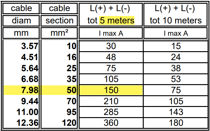
And when we look at Victron’s Recommended battery cables document, we see that they are recommending 50mm2 for currents up to 150A anyway (for cable lengths of up to 5m).
For a 1m cable the theoretical voltage drop is within their recommended range of 0.259V. But they explicity state that resistance leading to additional voltage drop due to contacts is not calculated into the recommended cables size.
Already a cable size of 2m will lead to over 3% and 0.3V voltage drop when the cell voltage is only 4* 2.6V = 10.4V (and by default raise a “Low Voltage Alarm” on the MultiPlus). And even a cell voltage of 4* 2.75V = 11V is close to 3% and over the recommended threshold (of course, calculation is based on full inverter load of 1600VA). Besides Victron explicitly recommends a voltage drop of under 2.5% in their Wiring Unlimited document.
So why is Victron fitting the inverters with only 35mm2 cables? Especially since they are using welding cables that are only rated up to 60°C. I do not know.
But I do know, how I can fit an additional 35mm2 pair into the inverter and minimise a potential heating problem.
Adding a second pair makes particular sense at least in my case, as I am using a JK-BMS and Eve cells that both come with two M6 terminals per connection point. So running two cable pairs to battery and BMS saves me from using a bulkier and stiffer 70mm2 cable that I would have to split at the BMS and main positive cell anyway. And with that, I can still use the Anderson SB175 connectors with regular housing and 1383 wire contacts and without having to resort to 2/0 housings and 1328G1 wire contacts.
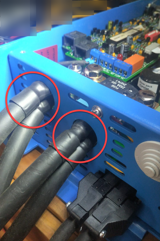
The inverter comes with 30mm holes in the front panel where the supplied cable is fitted with an M25x15mm cable gland (side note: why are they using IP68 glands when the whole inverter is only rated at IP21). Eland H07RN-F 35mm2 cable has a diameter of 14.6mm, so actually two of these cables do not fit through the holes at once.
But as the cable lugs are actually that long that they stick out of the chassis the required diameter is 2* 12.5mm = 25mm which is just the size of the hole. When wrapped in heat shrink we need some more space. And certainly we want a little bit of head room, so the cables do not scratch against the metal when moving.
So, the M25 holes had to be enlarged slightly to make space for the double cable lugs as seen on the picture below. I used a Hilti GDG 6-A22 grinder for this. I covered the inverter to prevent metal splices and dust getting inside (board, circuity) of it. And I added extra insulation around the cable lugs to prevent them cutting into the metal.
Bottom side of MultiPlus with enlarged holes and extra cable insulation
Mounting the cables to the connection points is done with two Klauke M8 35mm2 DIN 46235 compression cable lugs (back to back).
Note: the compression cable lugs from Weidmüller will not fit, as their connection plate is too long.
Instead of the factory supplied washers, spring locks and nuts, I use M8 serrated washers and lock nuts. As the negative connection point (which is directly under the 250A MEGA fuse) is around 2mm higher than with only one cable lug, I added an additional (copper) washer under the fuse terminal to make more space.
I could cover the original bolts with insulation tape to prevent accidental contact with the chassis when squeezed (but this is something that could have happened even before).
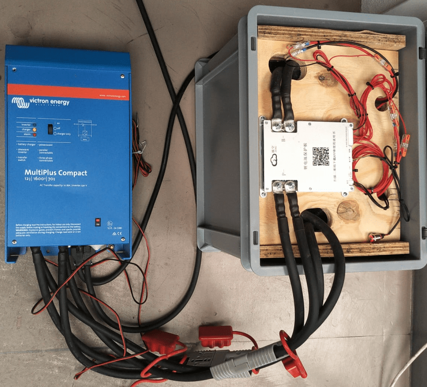
Victron MultiPlus Compact 12/1600/70-16 with dual 35mm2 battery cables
Now we have a 2* 35mm2 = 70mm2 connection to our battery as seen below.
2* 35mm2 connection between battery and inverter
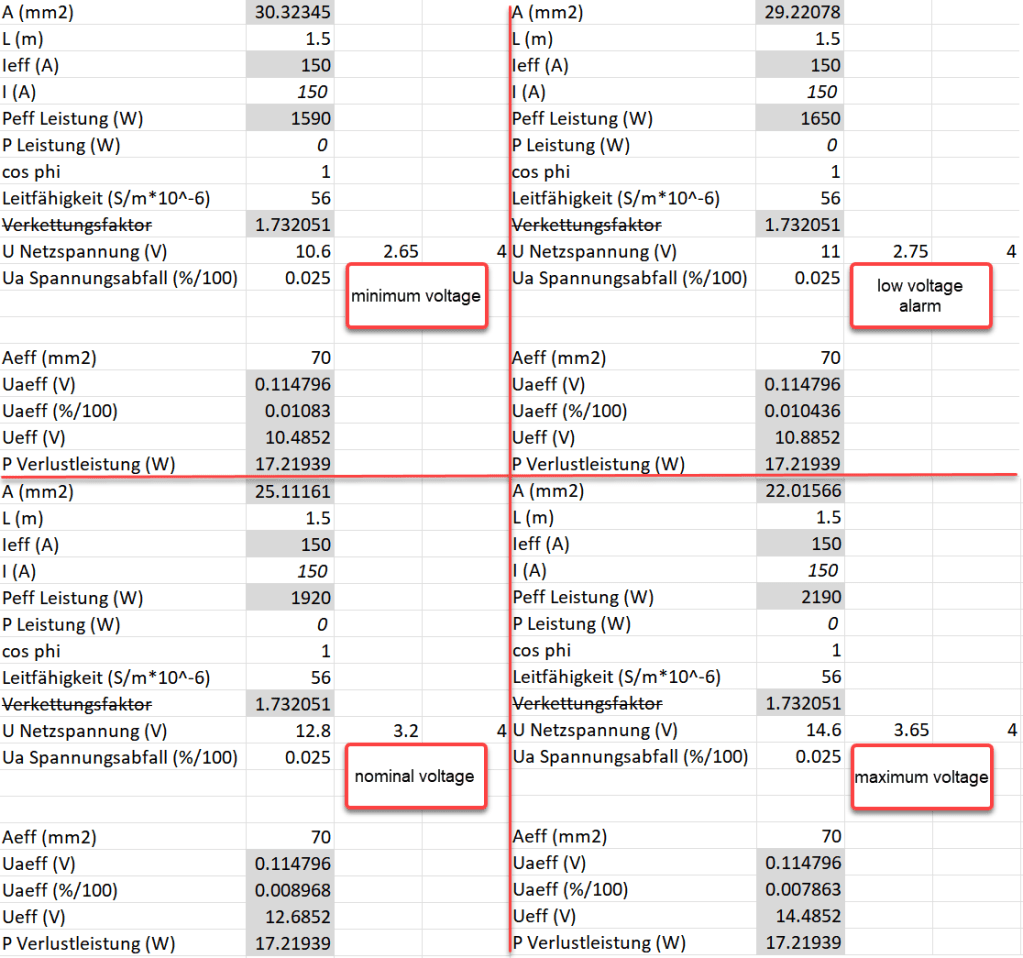
So the voltage drop over the whole cable (1.5m from invert to battery with 70mm2) should be around 114mV:
Voltage drop at different cell voltages
So as it seems, the main difference between the larger and the smaller cable is the power loss (17.22W vs 34.44W at full power or 15W vs 30W at 0.5C). So all in all we save nearly 0.84% battery capacity per cycle with the thicker cables (which is 5000Wh over the whole cell life) – probably less than we spend on the cables and lugs, the labour and the time to do the calculation and writing up the article …
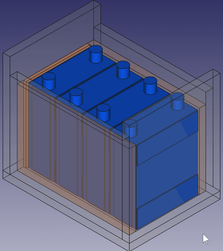
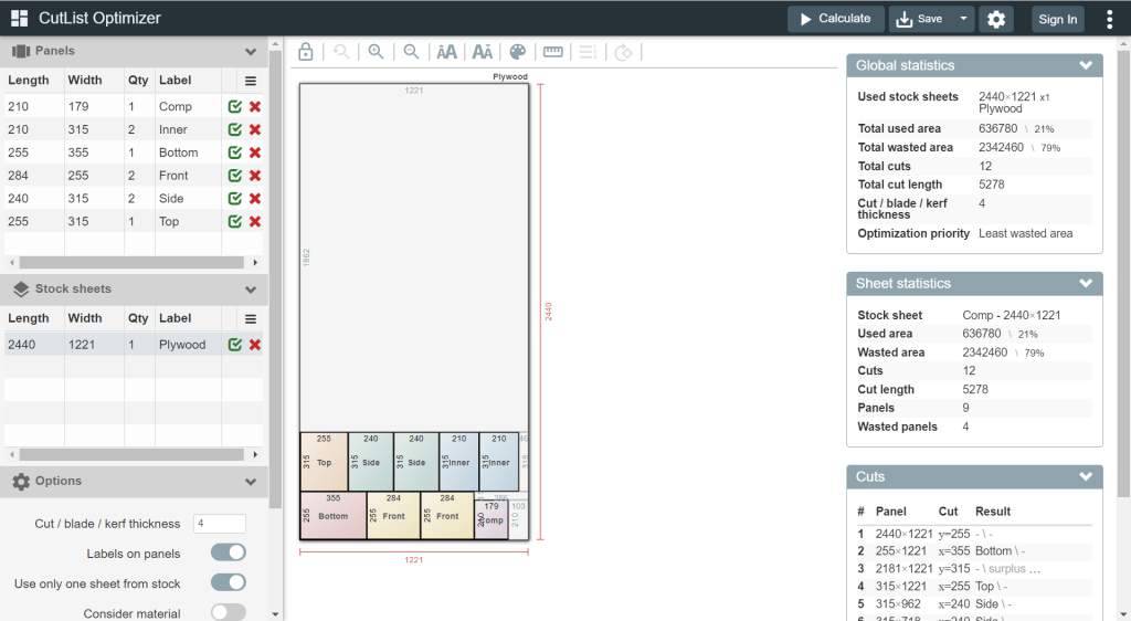
For this build, I planed all the boards after cutting, before putting in the cells. With this, I hoped to minimise the chance of any particles on the board damaging the cell insulation.
And for the small board at the short side of the case, I did also use 20mm plywood, but planed it several times until it I could just slide it in.
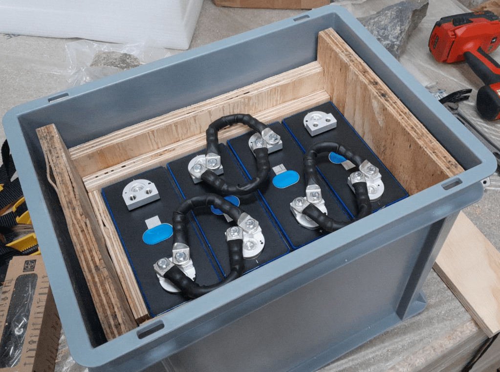
This is how the wooden case looks with the cells and insulation boards (shown in red):
Top view: battery cells with depicted insulation boards (shown in red)
Note: when using a JK-BMS I found it important to have the main negative connection point on the upper left (or lower right). Only with this orientation it was (relatively) easy to connect the cell to the BMS.
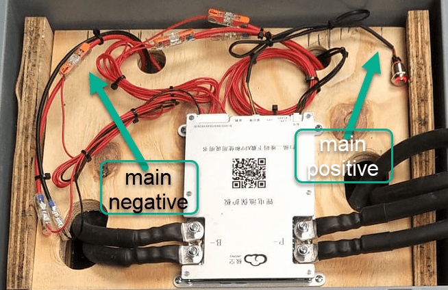
BMS connected to cells
It needed some fiddling to get the main negative cable pair to the BMS and the main positive cable pair out of the frame, as we can see from the image above.
The connection to the individual cells are fed through WAGO 221-2411 2 conductor inline splicing connectors. The holes into the top board were done with a forstner bit and a jigsaw. This version of the BMS can be fixed with four screws to the board (so no need for wire straps as with the 24s version).
Again, instead of a display I just used the pluggable power button that is connected to the display port of the BMS to power on and off the device.
In the end, I added Anderson SB175 connectors and 1383 (2AWG) contacts to both pairs and connected them to the inverter.
cell contacts were secured with M6 serrated washers and M6 16mm steel bolts;
BMS threads B- and P- were secured with M6 lock nuts to M6 16mm steel bolts (with the bolt upside down);
cell wires from the BMS were fitted with uninsulated ferrules;
cell wires on the positive cell poles were fitted with ring lugs and a 2.5mm2 hookup wire;
I added handles to the SB175 connectors to facilitate disconnecting the cable pairs;
I added dust covers to the SB175 connectors;
all compression cable lugs and the SB175 were crimped with a Hilti NUN54-22;
all cable lug connections and Sb175 were heat shrinked;
I added 2*35mm2 cable pairs with SB175 connectors to the inverter by replacing the existing 35mm2 welding cable with M8 lugs (you still need M8 lugs on the inverter positive and negative terminals).
Things to improve next time
Mount the SB175 connectors to the outside of the container With this the lid can be closed and the cables and BMS are better protected against pulling;
add 3A inline fuses to the cell wires;
use 45° angled cable lugs for main positive and main negative to make it easier to get the wires routed outside the container;
feed an additional wire pair for the voltage sensor from the main positive outside the container to be able to connect it to the inverter (but I am not too sure about this, as I think the voltage drop on the 2*35mm2 connection is neglectable – it might better to add a temperatur sensor to the main positive):
add a Victron MK-3 USB-C interface with RJ-45 cable into the case (to be able to restrict AC power on the inverter).
What did it cost?
Cost calculation for the 4s battery including case and inverter
Summary
This case is not as complete as the 8s version – due to its form factor. Neither the inverter has an RCBO nor the battery has a DC MCB. This has to be added separately (incurring additional cost and space). As written above, the 4s version is more like a traditional battery. However, the form factor is quite compelling; 3.5kWh in 400mm x 300mm x 325mm case. Especially in combination with the compact edition of the Victron MultiPlus. And the cost (as always without labour) is very reasonable, as well.
The inverter delivers 1200W constant power – in my opinion, enough for a small and mobile electricity build. Runnig a Krups Inissia Nespresso machine is not a problem, and boiling water with our 1000W immersion heater neither. Worst case, you could also run a 300W infrared panel heater for more than 11 hours.
One drawback of the inverter is probably the relatively small charger. With 70A at 12V it can only charge the battery with around 840W. This is certainly not the problem of the battery which would support charging up to 1344W.