In this article, we have a look into the software options of the Siglent SDS2000X Plus digitial oscilloscope series.
The SDS2000X Plus series has been around for quite some time and – while still on sale – has been superseded by the Siglent SDS2000X HD series. It consists of a 2-channel entry model and three 4-channel models with varying bandwidth (100MHz, 200MHz, 350MHz). Interestingly the hardware in these models is exactly the same (with the one exception of the 2-channel model only having a single acquisition unit). For more details have a look at this video where the device is taken apart:
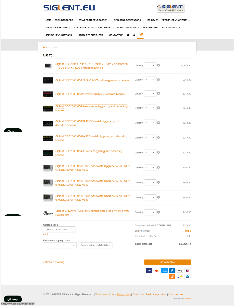
As mentioned in the video, there seems to be the possibilty to upgrade the bandwidth of the oscilloscope to up to 500MHz and additionally unlock a few other options. According to the manufacturer’s web site the value of the software options can add up quite considerably to a multiple of the actual oscilloscope:
The author of the video, which partially seems to divide its audience by its tonal pitch, remains cryptic about on how to actually do this but only refers to a post on this forum. So the question remains, is this really doable? and if yes, how does it work?
Note1: In case someone is wondering if it is allowed to generate software keys, an option might be to contact the manufacturer to get clarification on this subject.
Note2: I bought my scope with a couple of software options. So, no need for me to generate keys, I would not have otherwise.
The questions
According to the forum there seems to exist confusion about the following areas:
- What is the
SCOPEID?
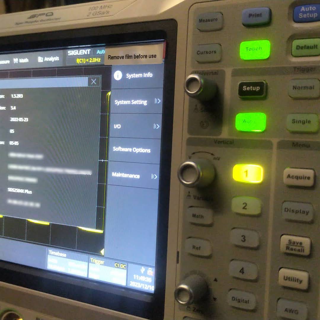
TheSCOPEIDis the 16-digit value you find when you open Utility, System Info and strip of the dash characters from “Scope ID“. - What is the
Model?
According to this video the model just stays as it is. So no replacing of the pre-defined value at all (regardless of the actual model we have). - Which firmware versions work with it? And do I have to downgrade first?
As it we can read from the Siglent SDS2000X Plus Release Notes, beginning withv1.3.9R10no downgrade can be done to any version older than that version. In the previously mentioned video we see that exactly that version is used for the demonstration. - Which keys (based on
bwopt) work for which option?
The script generates keys that do not necessarily match 1:1 to the options in the oscilloscope. But a look and search into the user manual reveals that the abbreviations in the script correspond to the product numbers. So for example,MSOis the abbreviation for the 16-channel logic analyser option. However, some keys generated by the script do not seem to have any corresponding sotware option at all (such asMAXorWIFI). - How to generate keys for options originally not included in the script (eg.
MANC,SENT)?
There are options present, especially theMANCHandSENToption, that are not being generted by the script at all. All one would have to do, is to addMANC(mind the missing ‘h‘) andSENTto the array ofbwoptand have to re-run the script. - Is there any order in applying the software option keys? Or anything else to consider?
Everytime a new key is entered, immediate feedback on the screen shows if a key was accepted as valid. A reboot seems to be required to activate the associated function. However, it is not problem at all to insert multiple keys or software options without rebooting.
A special note about the bandwidth option: as one can see from the web site, it is not possible to buy a500MHzlicense upgrade for aSDS2104X. Only the200MHzoption is available. After appliying an upgrade the actual model number of the oscilloscope changes as well and a new bandwidth option appears for that new model. So essentially, an upgrade on aSDS2104Xto a500MHzversion (SDS2504X) must be done via these intermediate steps:200MHz,350MHz,500MHz. In the end, only the label printed onto the oscilloscope shows its true origin.
An upgrade to a more recent version of the firmware afterwards is possible but optional.
Note1: after upgrading to500MHzthere is no more bandwidth option thus reducing the number of license options by one. I mention this, in case you thought something went missing.
Note2: the standard probes only work up to200MHzand also the high-end probe goes only up to350MHz. So, in order to be really able to use the full500MHzone probably has to get hold of an active probe.
The script
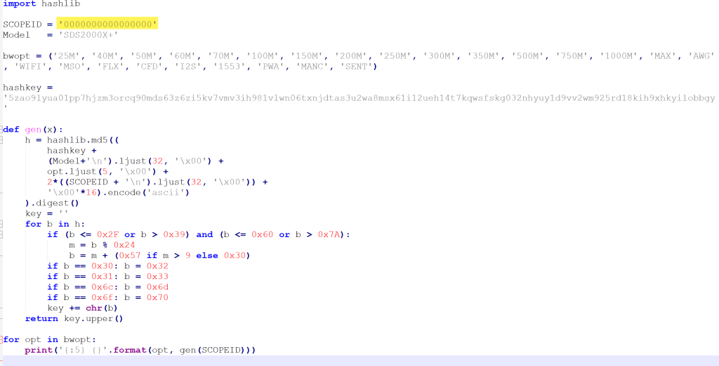
The script itself is pretty basic. The magic MD5 hashkey is being mangled with the Model and the SCOPEID. And then for each bwopt a new key is generated. Interestingly, the gen function never makes use of its parameter x and opt is implicitly referenced from the global scope.
The conclusion
Essentially, this has been a story about weak license keys. Though it might seem perfectly doable to generate keys for software options without reyling on the manufacturer, this is not something that can be generally recommended.