

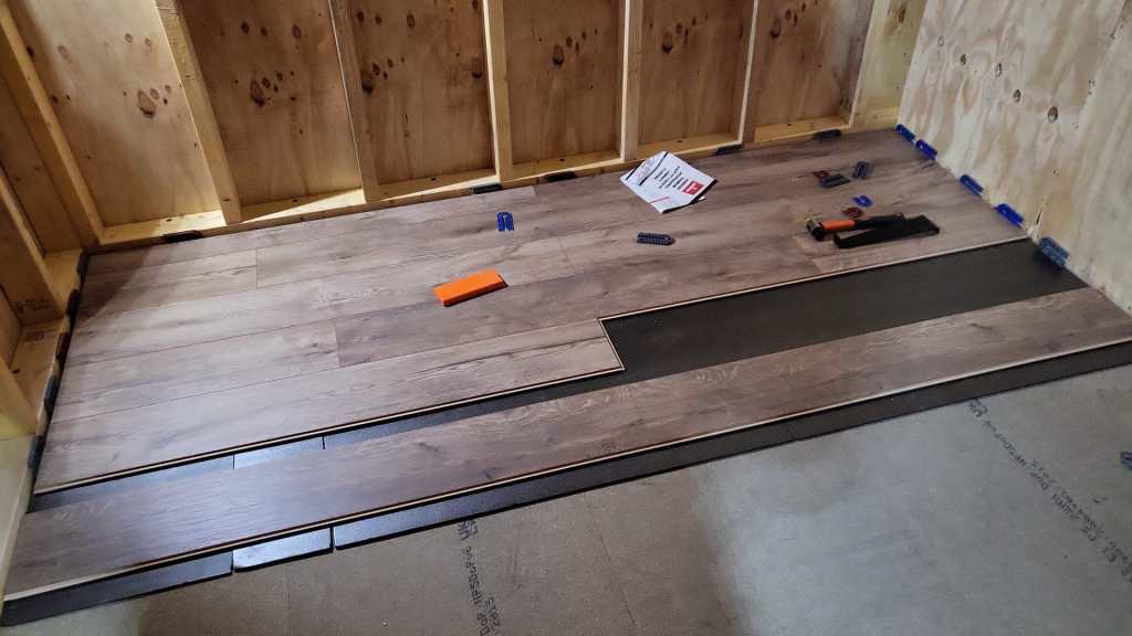
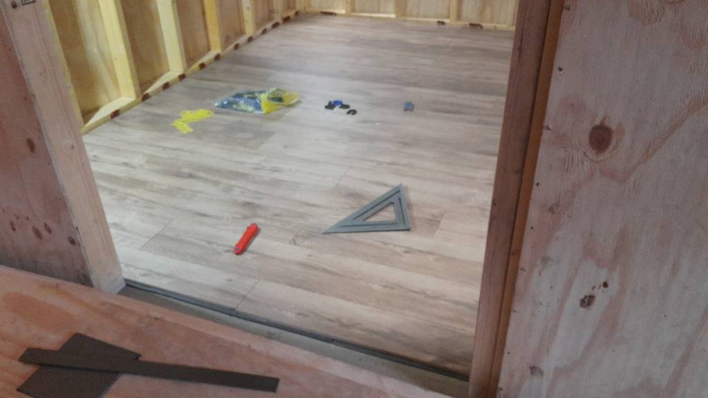
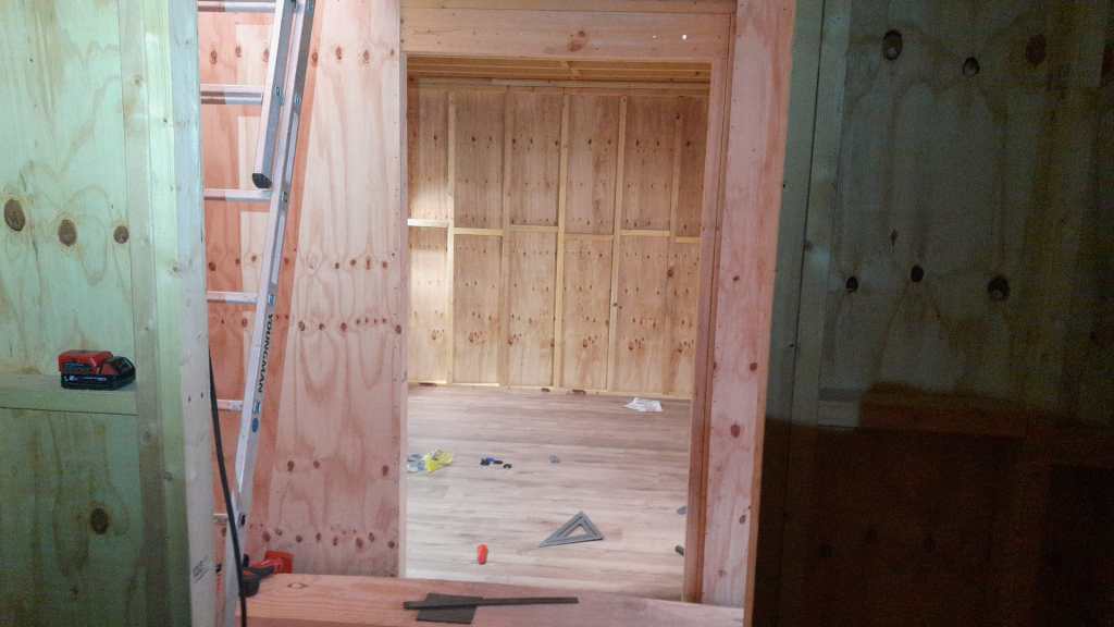
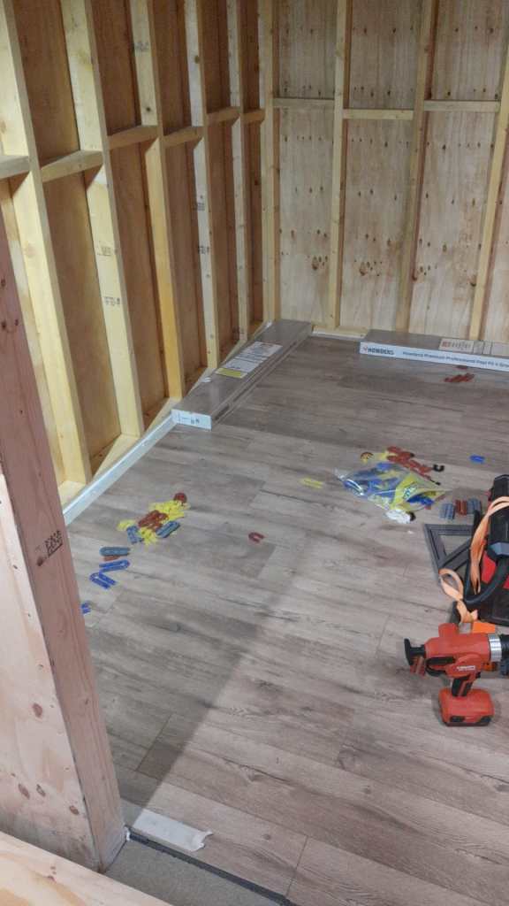
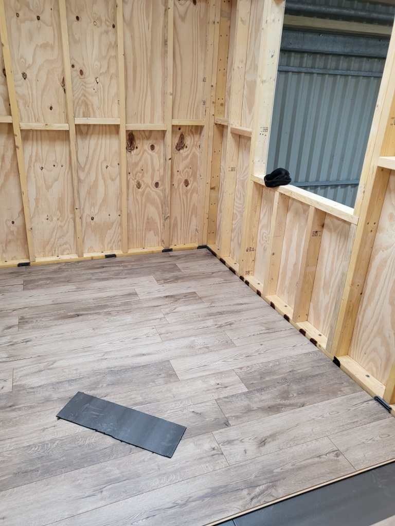
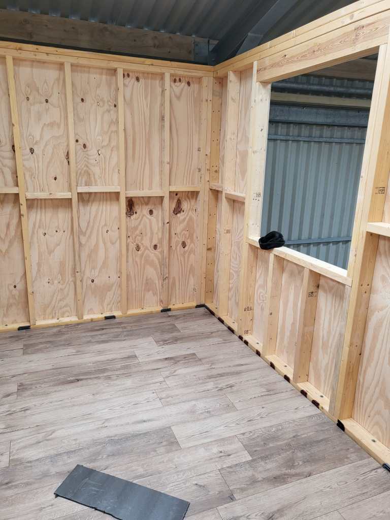
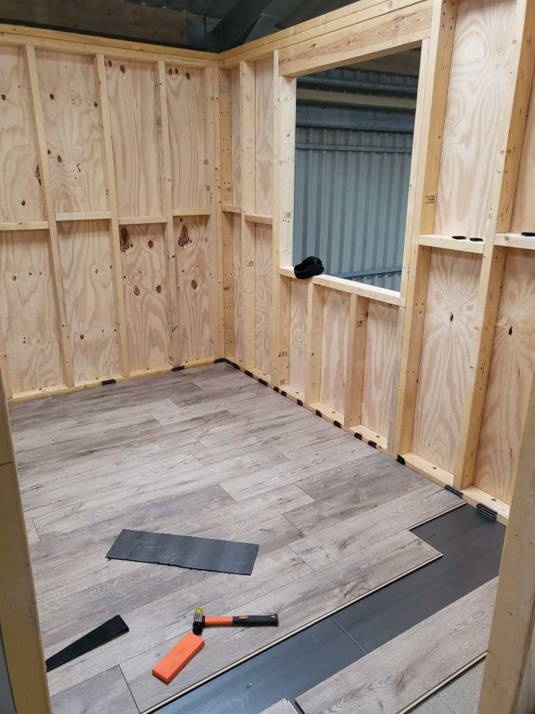
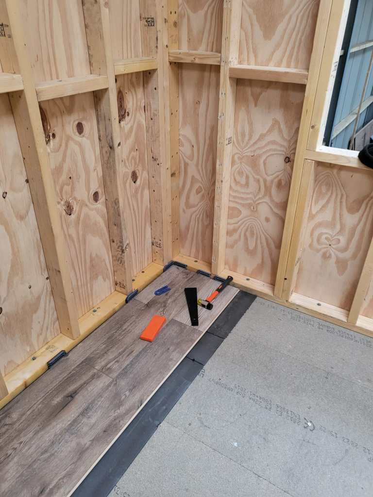
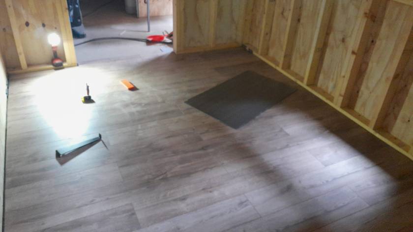
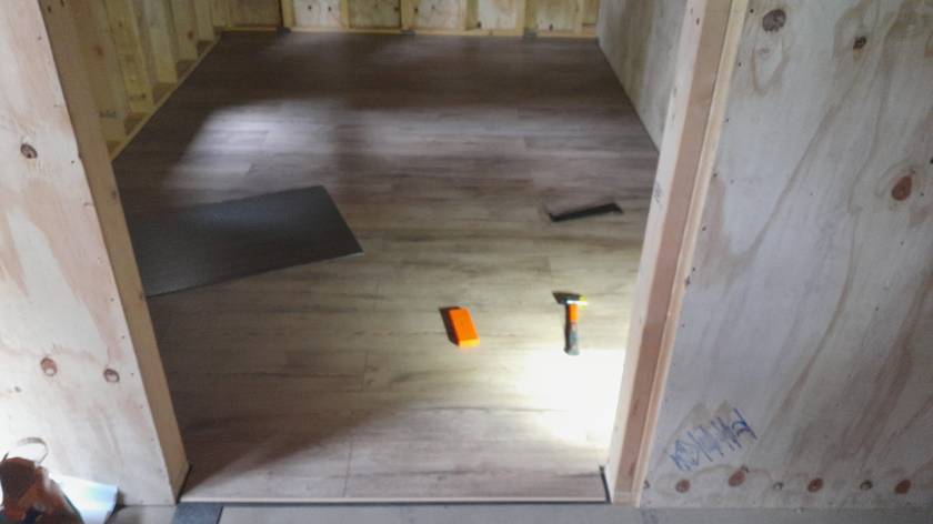
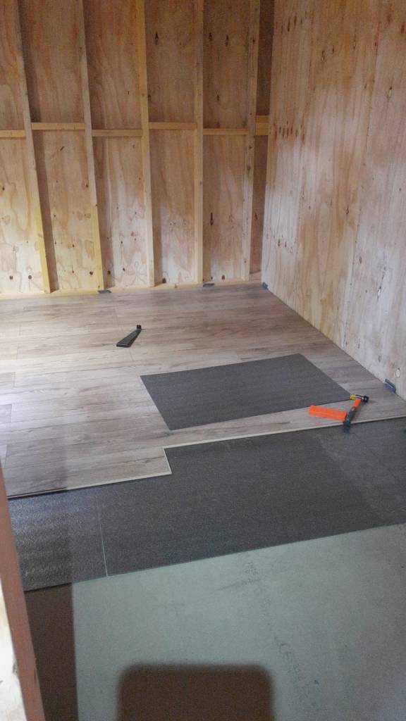
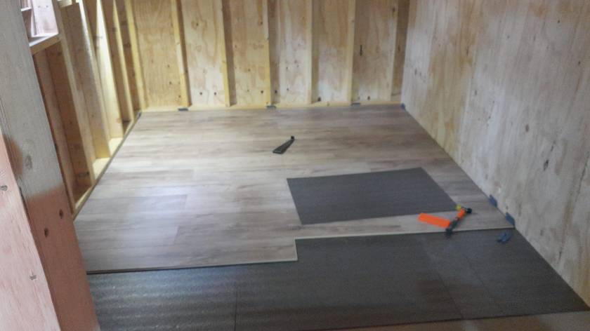
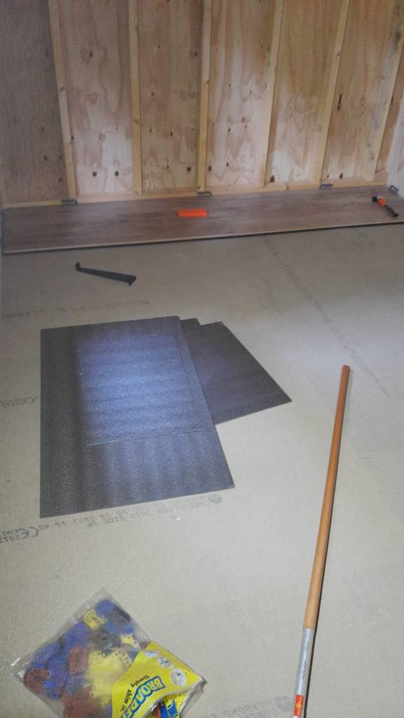
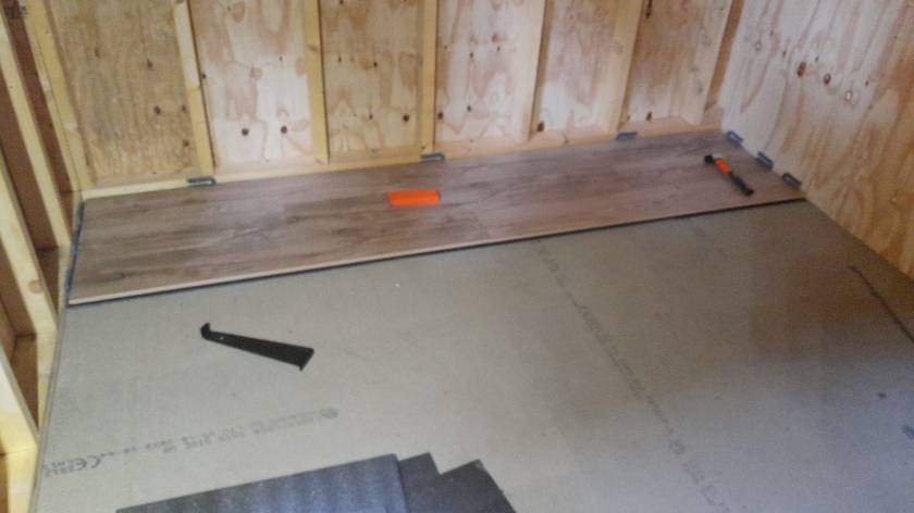
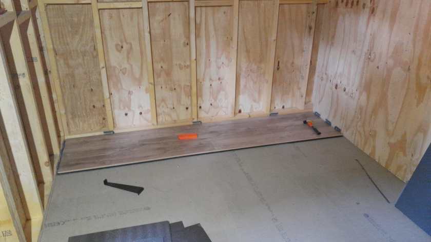
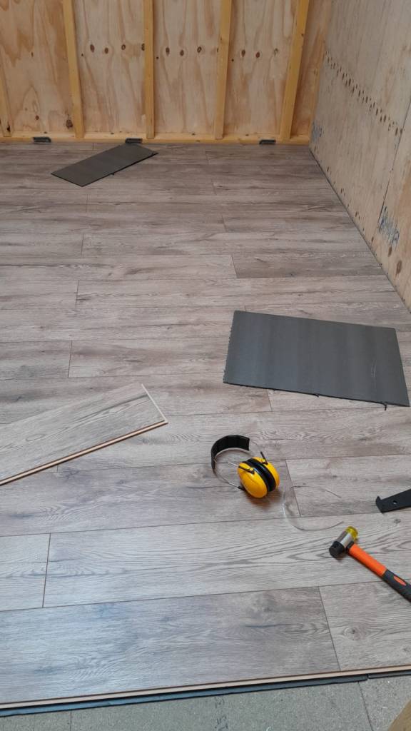
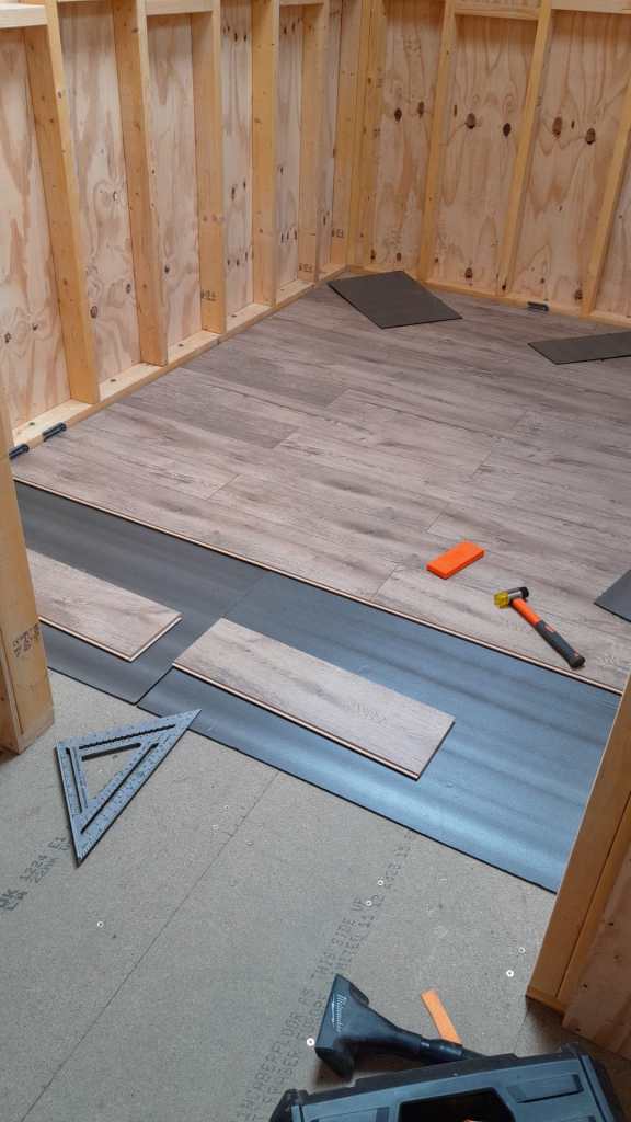
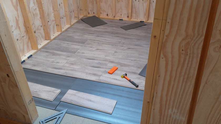
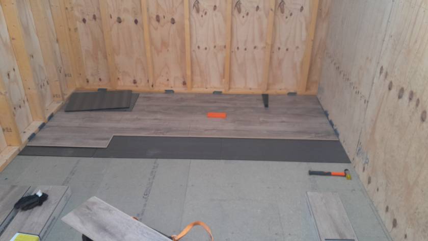
Another update from the flooring department. We started and finished the Storage Room. Now, on the ground floor only the Utility Room and the Hallway are to be done. Getting closer. Meanwhile the future bath room serves as the current storage room.
Author: Ronald Rink
I am a senior auditor, consultant and architect at d-fens for business processes and information systems.


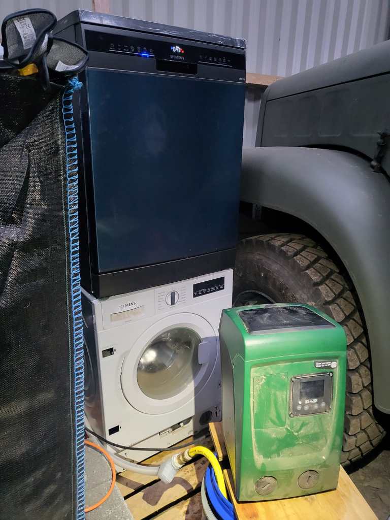
Washing Machine and Dishwasher Tower
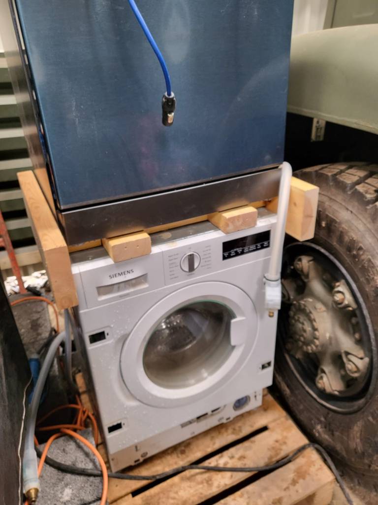
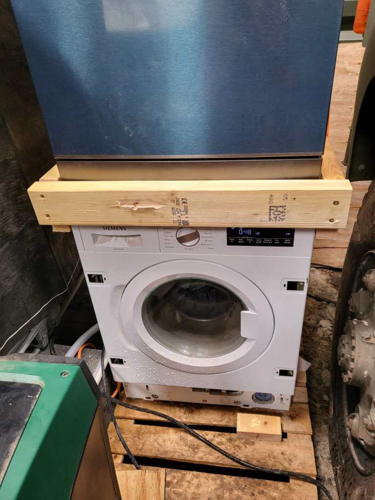
As we wrote previously, we installed a dishwasher – and sat it on top of our washing machine. Currently, the only place where we had space _and_ water in reach …
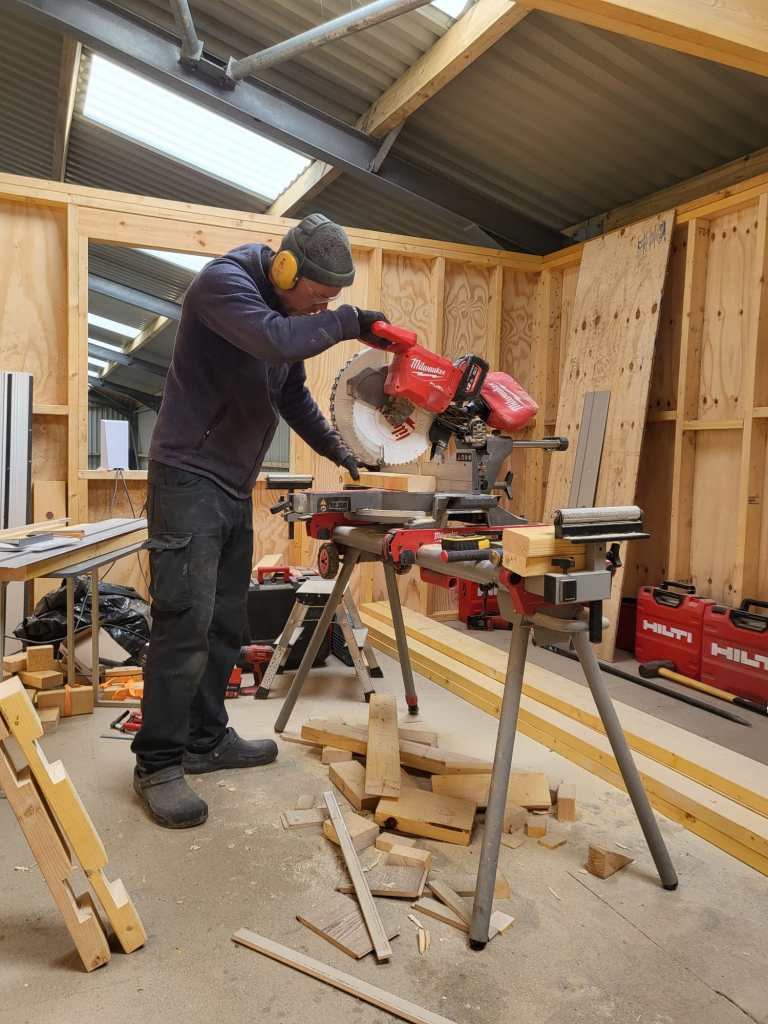
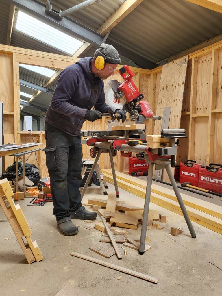
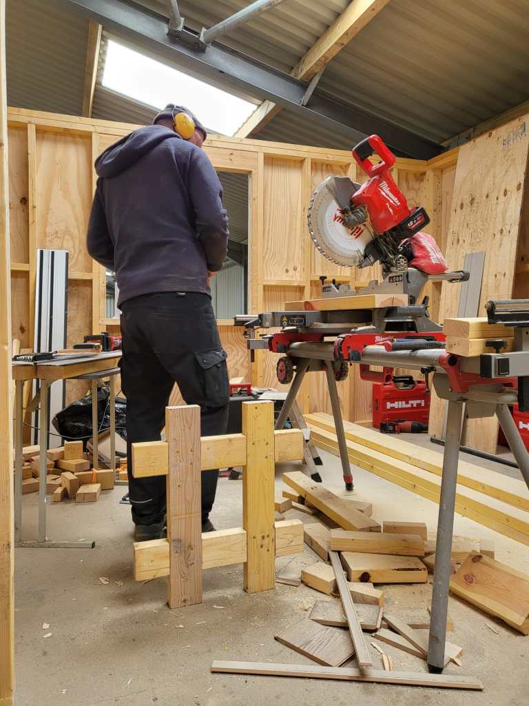
But operating the washing machine not astonishingly proved very unstable – at least for the dishwasher. So, we decided to create a luxurious frame to sit the dishwasher and hold in place when the washing machine was spinning.
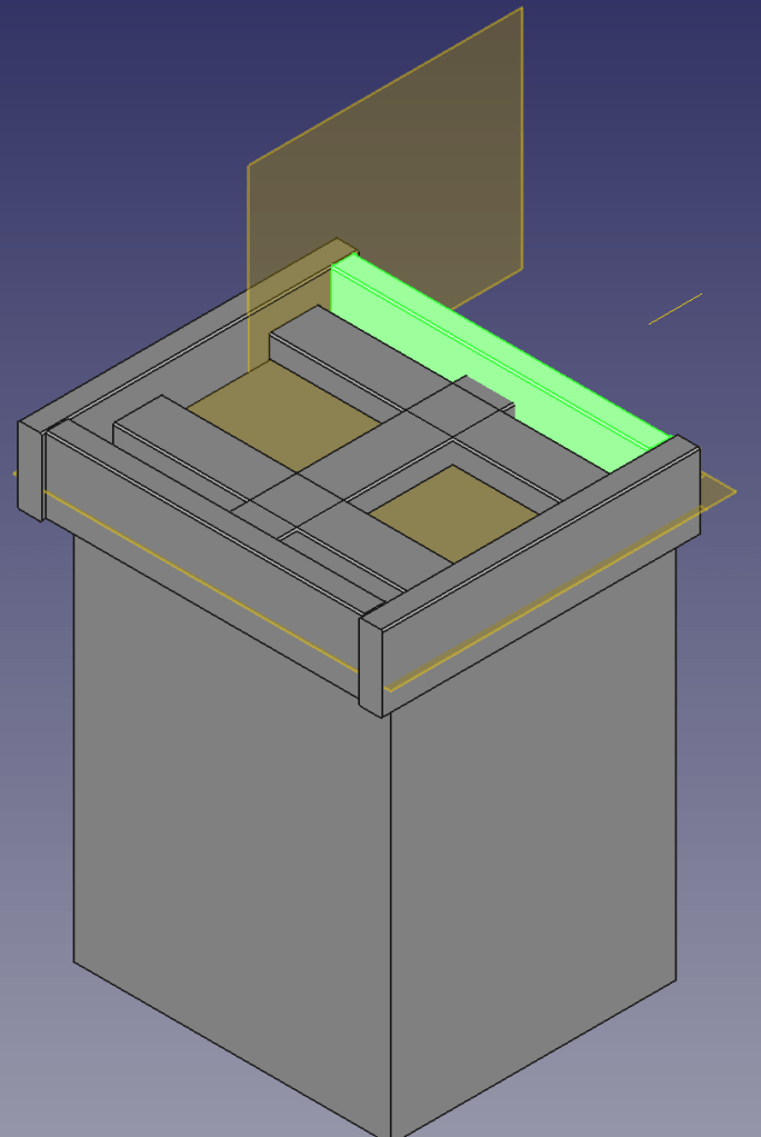
Not being agile but very waterfall, I needed a concept first. So, I fired up my trusted CAD programme and started sketching …
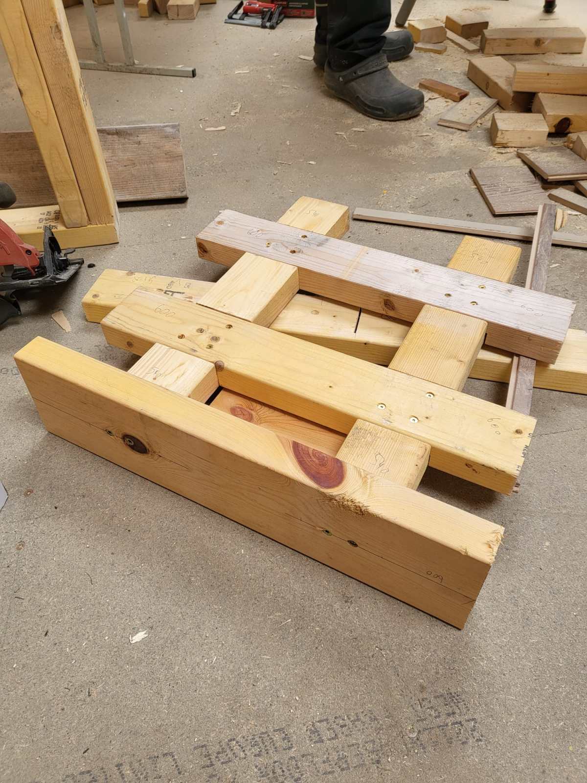
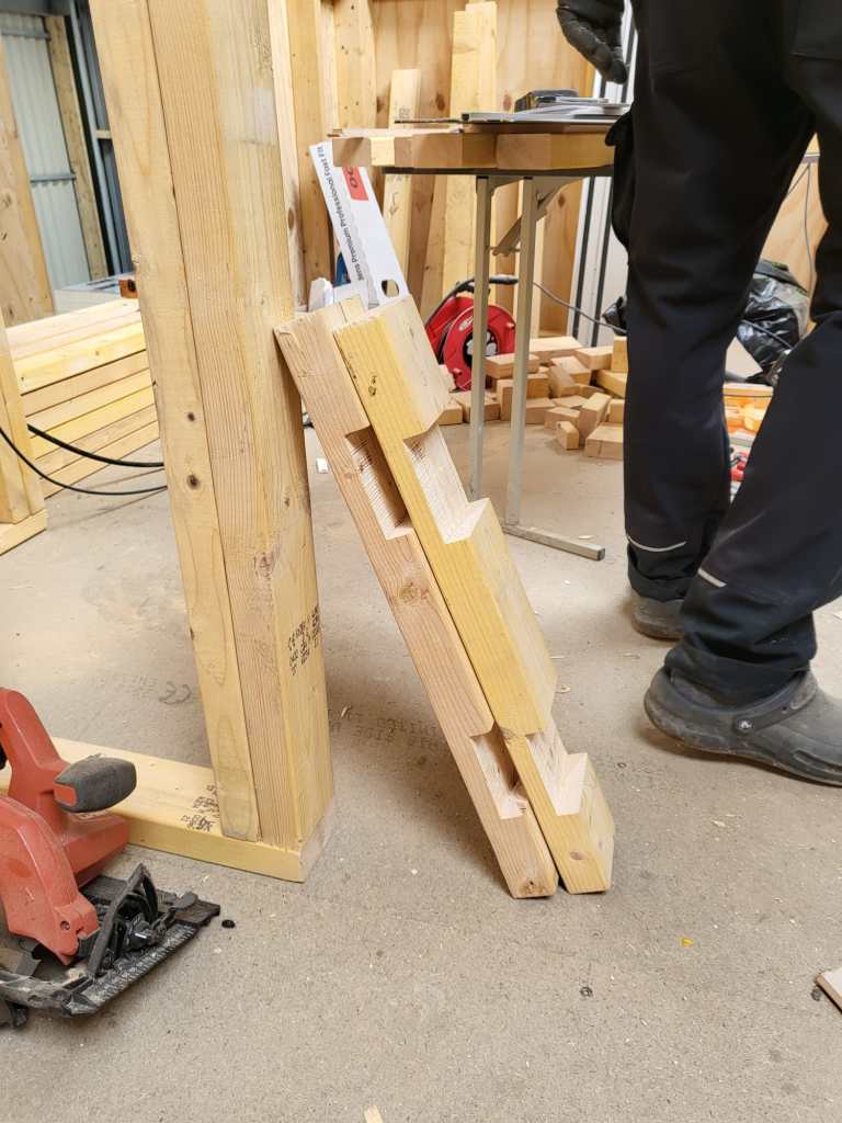
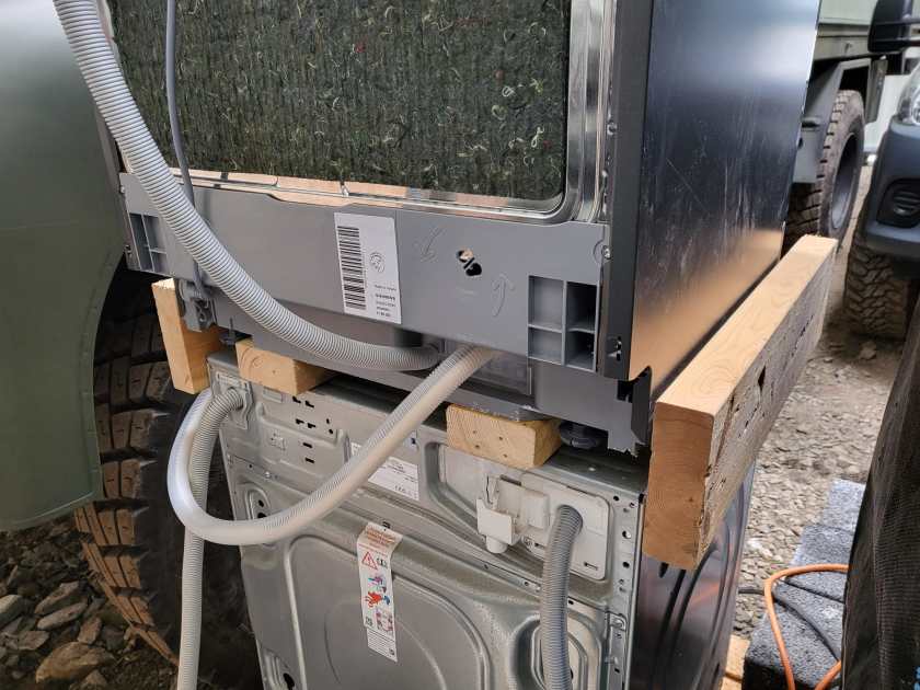
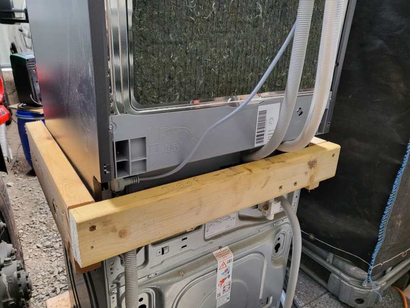
4x2s intersected with other 4x2s surrounded by 6x2s – that was the way to go.
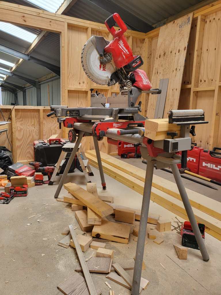
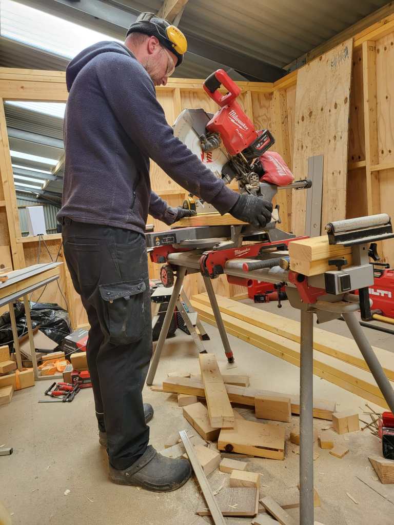
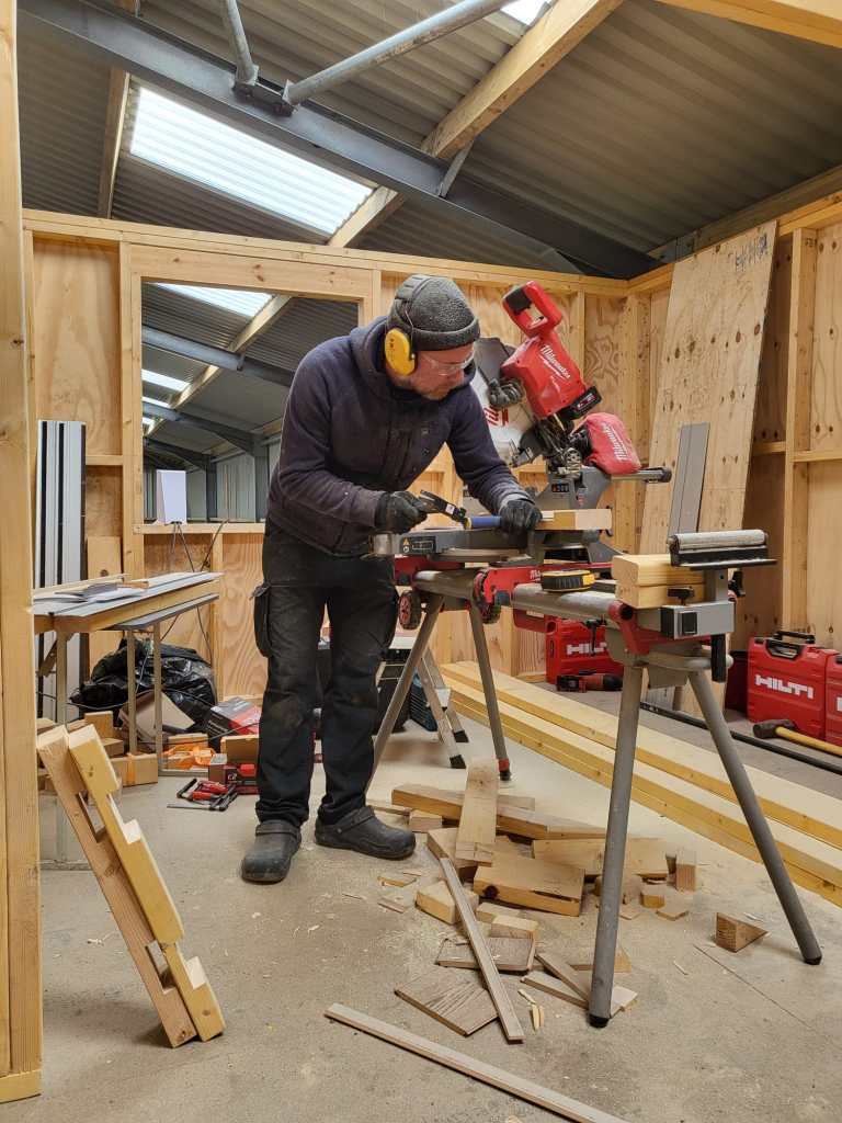
So, first I cut the intersections of the 4x2s and used chop saw and chisel to get the cross sections.
Later on, we added 6x2s so the dishwasher would not fall off. And at the end, not visible on the images, we added a strap around both devices to stop the dishwasher from bouncing off – just in case …
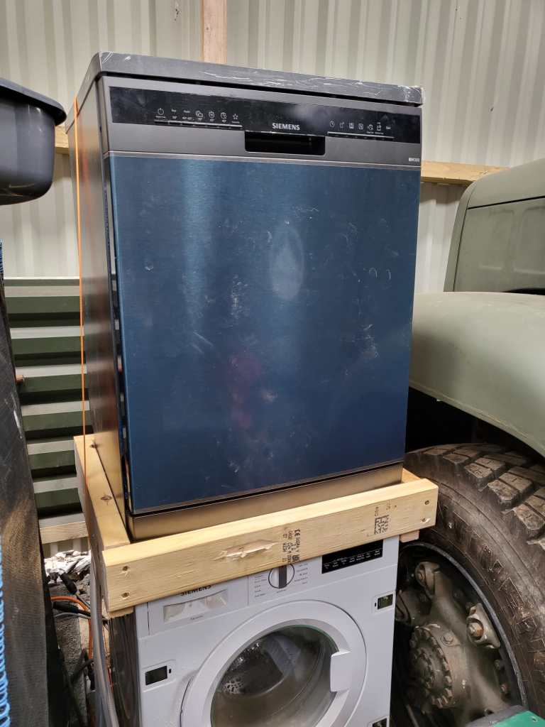
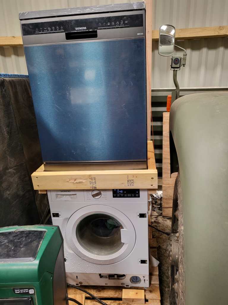
Now we have a washing tower – until we move it into our new kitchen. And this is all I can tell. See for yourself.


Creating a parametric Universal Beam in FreeCAD 0.21.2
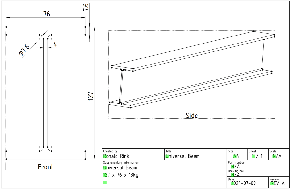
While designing our future heavy-duty pallet shelf, I had to try with different Universal Beams (UB, BS EN 10025-2). And though, there are plenty of templates to reuse I _had_ to create a universal beam myself.
The main reason was and is, I wanted to be able to quickly change the dimensions of the UB in a single place and reuse it with other parts and bodies I created.
However, it took me three attempts to create a stable model, that would survive any resizing… and here is what I learnt:
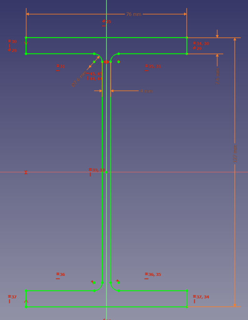
I started the sketch with three rectangles, which I – after attaching and trimming them – constrained with the overall beam parameters. The arc/radius was the tricky part. I either ended up overconstrained or un-stable where edges would flip. So, I removed (nearly) all constraints like symmetric, parallel, horizontal, equal (except for the overall dimensions), added the arcs, coincided the points with the neighbouring edges and manually coincided the points of the remaing edges. Only then I re-created the required symmetric, parallel, horizontal and equal constraints.
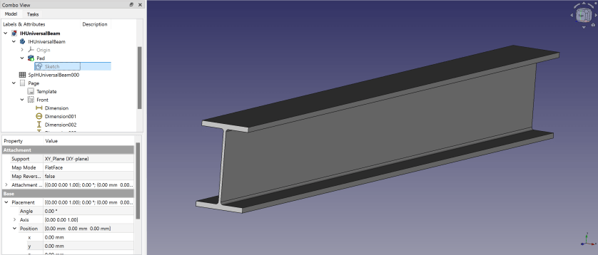
Here is a 3D view of the resulting beam:
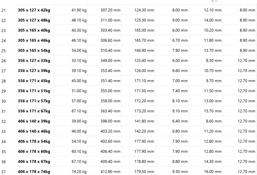
I then added another 30+ UB dimensions to the spreadsheet so I could use them in the beams constraints via expressions. If I now copy any of the existing value of lines 5 following to line 3 into the yellow cells the beam is automatically resized.

So, this is the beam and how to use it. In case you are interested, you can download it at grabcad.com:

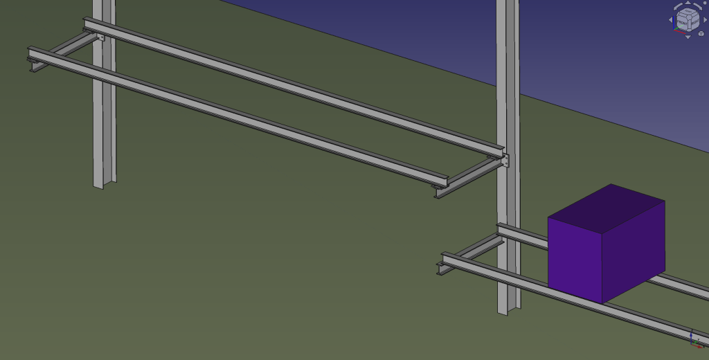
And here is a sneak preview of how the final shelf could look like:
I again, still and always find it ranging from very difficult to frustrating to work with FreeCAD to create stable models – especially when they are parametric. But hey, this is FreeCAD as in free software.
Our PIR Insulation Boards arrived
What a day! We got a call from Rembrand asking if they could deliver the PIR boards we ordered a day earlier. Sure they can! We quickly made space and waited fo the truck to deliver.
In my calculation the complete pile of boards would sum up to roughly 8m. Quite a load – especially with today’s wind! The truck actually did a tour just for us …
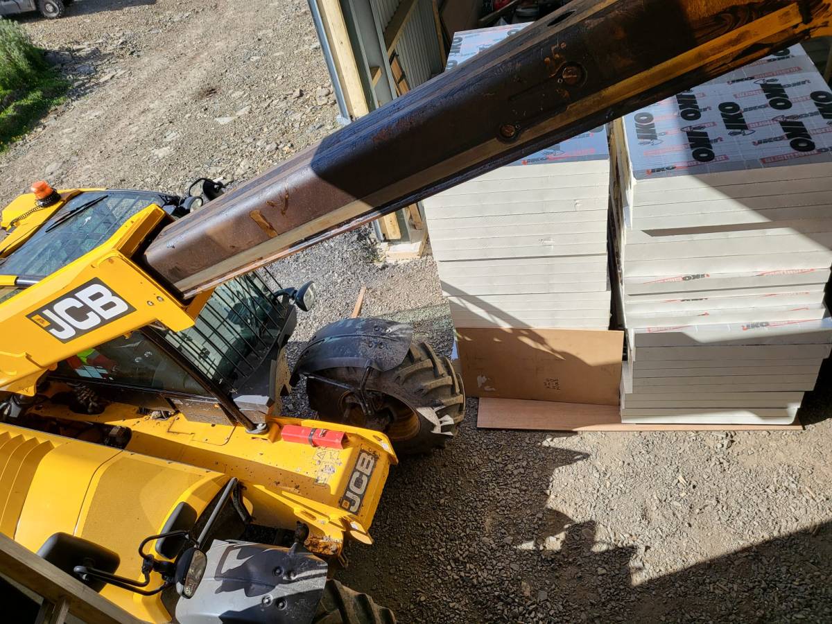
And then we drove the load over to our plot – all the way from the main road. It took four round trips to get everything (64 * 2400 x 1200 x 90mm, 20 * 2400 x 1200 x 140mm) into the barn.
And then we had to find space to store them …
Luckily, we designed the hallway of our tiny-house-in-barn with a 1450mm width and all doors 1080mm wide. Enough space to store some of the boards in one of our just ready-laminated rooms on the first floor. No problem lifting it with the TeleHandler!


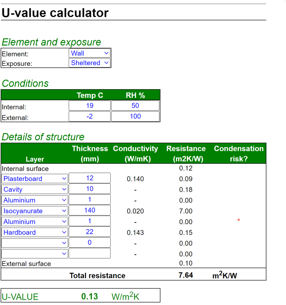
When we ordered from Rembrand the actual manufacturer was not specified. But upon delivery we could see the brand – IKO. According to their web site the thermal conductivity lambda for the material is 0.022 W/mK. For the walls this gives us a U-value of 0.18 W/m2K. Just what the building code asks for …

For the floor things look even better – with thicker boards the calculated U-value fits the requirement of the code as well: 0.13W/m2K. And this does not include our laminate floor and the insulation layer under it.
So, now we just have to choose what to do next. Installing the roof, continue with flooring or start insulating the walls …
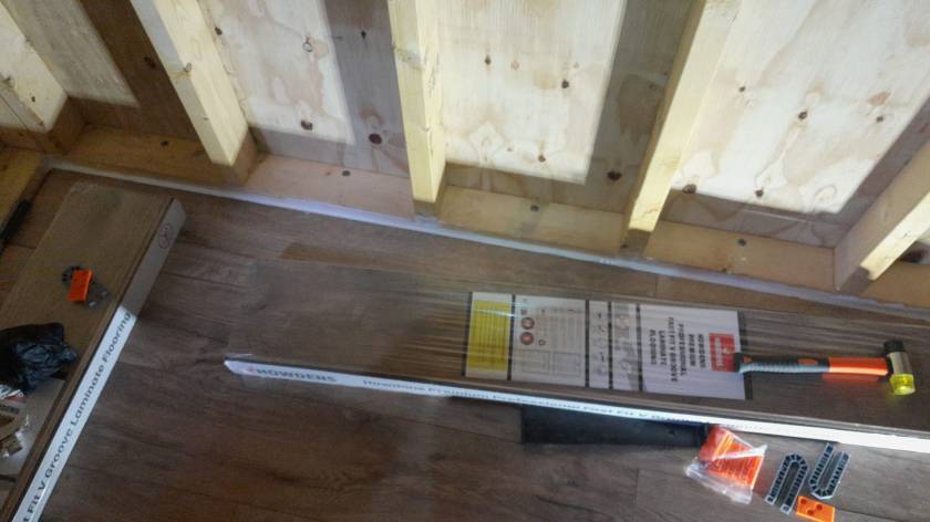
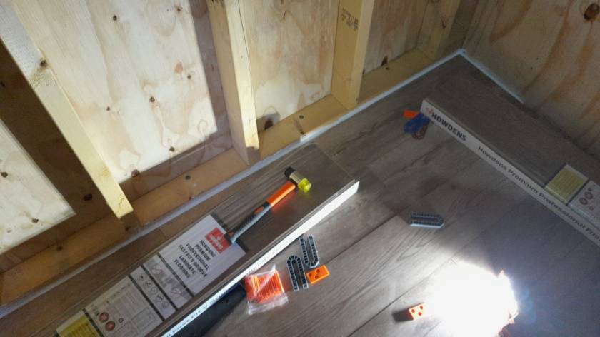
Current state of our Laminate Flooring

Here is a quick overview of the current state of our laminate flooring: By now, we completed the kitchen, the bathroom, the bed room and the study.
Still to do: utility room, storage room, living room and two hallways. So, not quite there yet.
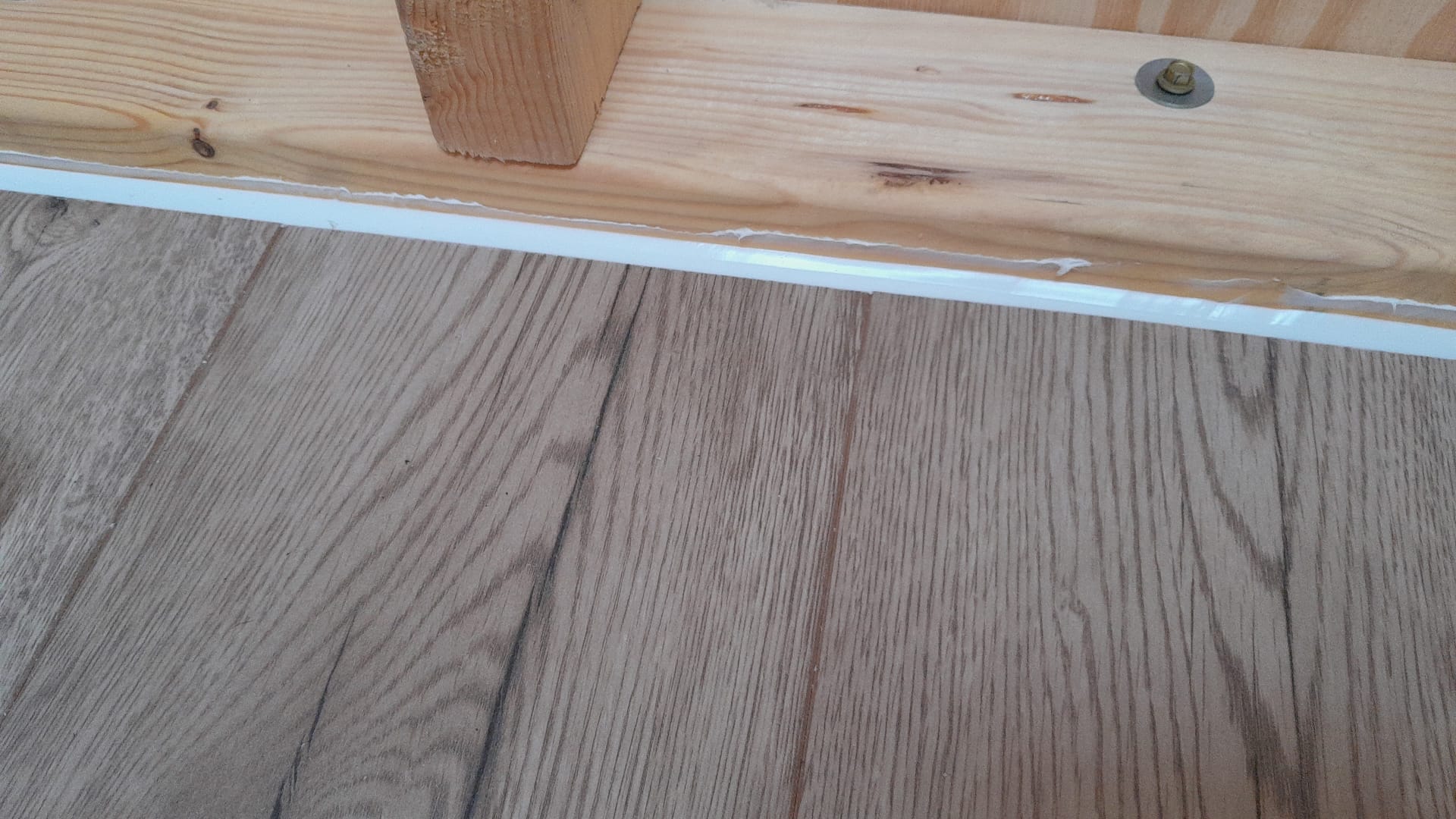
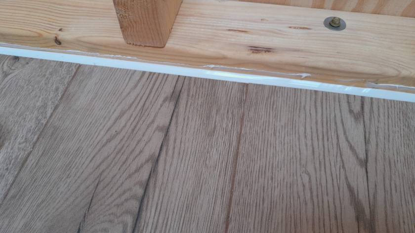
Our initial silicone tests showed we would use way too much silicone (around 6* 310ml per small room) to fill the required 12mm gap between the laminate and the wall. So, we went for a 10mm foam backing rod and put the silicone on top – with the help of a Hilti Dispenser and Fugenfux. We got the silicone from Screwfix: Sanitary Silicone White 310ml 12 Pack. And the result looks like this:

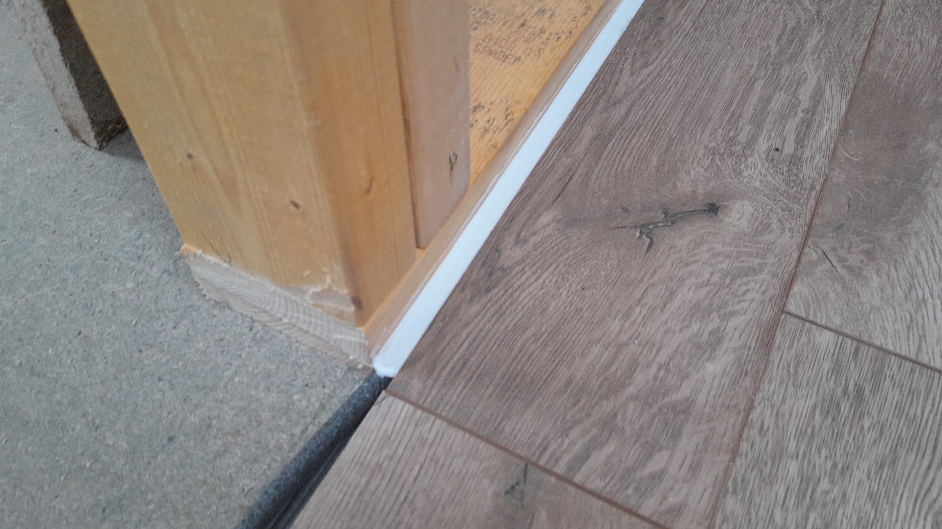
For the skirtings we will use 19mm x 19mm x 1.6mm 90° Aluminium angles from Metals4U that will cover the silicone and any imperfections. But – thanks to DX (a courier company with an impressive TrustPilot score of 1.4, 1.2 or 1.7) – who lost the package in transit already twice – we are still waiting for the actual delivery …


Again, we are not there quite yet. But making progress. So, hopefully in a couple of weeks we are done.
Another milestone: Dishwasher
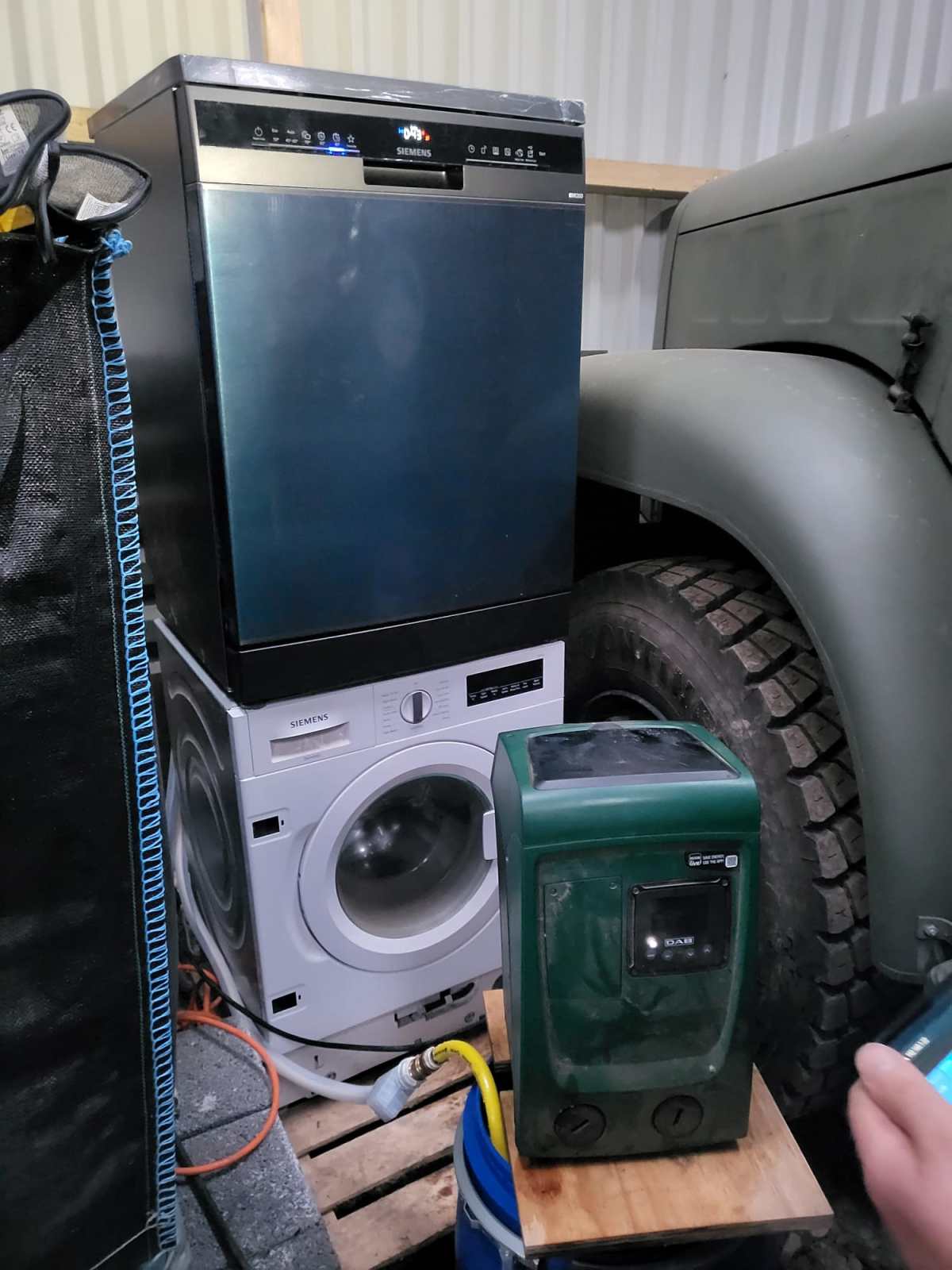
We definitely moved beyond Maslow’s pyramid and introduced a dishwasher to our ever growing list of utilities – which by the way fits nicely next to our Saurer 2DM … It is a Siemens iQ300 SN23EC03ME which is also driven by our DAB Esybox Mini 3.
What we found out so far:
- Water consumption is much higher than advertised even when using the 45°C/45min programme.
- Power consumption seems slightly higher than advertised as well with a peak consumption of around 2200W.
But all in all, we still save time, water *and* power compared to washing up by hand. And this holds true even for much less energy efficient dishwashers with an energy star rating of D or worse.
So, next time I buy a dishwasher I think twice if I spend a 100 quid extra on a more power efficient device – especially, when using solar for most of the year …
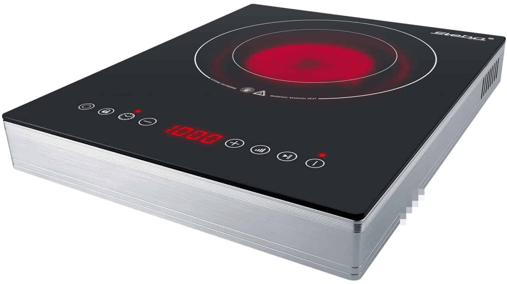
Glas ceramic hob Steba HK 30
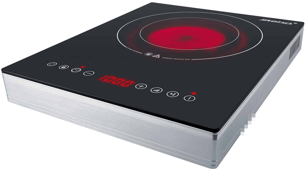
In order to cook in our Toyota Hilux and Toyota Hiace we use a glass ceramic hob Steba HK 30 that – according to the manufacturer – allows for precise adjustment of the power consumption from a company called Steba. However, in reality these ratings seem to be different. In this article, I give an overview of the energy ratings I measured.
Observed Power Consumption
The hob has 2 rings with a nominal rating of
- Ring 1
100w, 400W, 600W, 700W, 800W, 900W, 1’000W - Ring 2
200W, 800W, 1’200W, 1’400W, 1’600W, 1’800W, 2’000W
In the table below you see the actual values I measured in comparison to the nominal values as shown on the hob. For our Victron MultiPlus Compact 24/1600/40-16 the highest setting is on Ring 2 with 1600W nominal.
| Ring | Wnominal | Waverage | Wmin | Wmax |
|---|---|---|---|---|
| 0 | 0 | 0 | 0.4 | 4.1 |
| 1 | 100 | 200 | 225 | 254 |
| 2 | 200 | 450 | 417 | 459 |
| 1 | 400 | 400 | 375 | 409 |
| 1 | 600 | 475 | 450 | 477 |
| 1 | 700 | 600 | 580 | 602 |
| 1 | 800 | 700 | 708 | 731 |
| 2 | 800 | 750 | 699 | 770 |
| 1 | 900 | 860 | 850 | 863 |
| 1 | 1’000 | 930 | 932 | 934 |
| 2 | 1’200 | 900 | 863 | 901 |
| 2 | 1’400 | 1’150 | 1’108 | 1’148 |
| 2 | 1’600 | 1’400 | 1’368 | 1’396 |
| 2 | 1’800 | 1’650 | 1’645 | 1’659 |
| 2 | 2’000 | 1’800 | 1’787 | 1’795 |
Other Observations
There are a couple of (negative) things that I noticed when using this hob:
- When using the outer Ring 2 (or the full hob) the lowest level you can choose is 200W or then already 800W which turns out to be too much when trying to cook for a longer period of time. In my case, I use a large cast iron pot and let it cook for 4h to 5h. With 200W it was too little and with 800W it effectively started burning its contents at the bottom.
- After 2h – 3h of constant use the hob once switched off after the pot boild over and spilled sauce on the hob. But I do not know if this was just a coincidence. After turning it back on it worked without interruption for another 2h – 3h.
- The hob pulses when heating, i.e. turning the heating rings on an off very quickly. This seemed to stress the inverter when it was connected to mains (which was another inverter on batteries). For whatever reason it quite often drew power from the battery instead from mains.
- After use the hob keeps a ventilator running for approximately 15min. It is rather on the loud side but not necessarily disturbing. Power draw during the cool down phase is 4W. When cooking something on the move one has to take that duration into consideration before switching it off.
- The device is relatively bulky for that it is meant for only a single pot.
Summary
Most of the devices are not perfect (as described in the observations above). But all in all I really like the hob and we use it quite often. It is easy to clean and usable over several hours of constant use. Bon appetit.


Addendum
./.
Corrigendum
./.
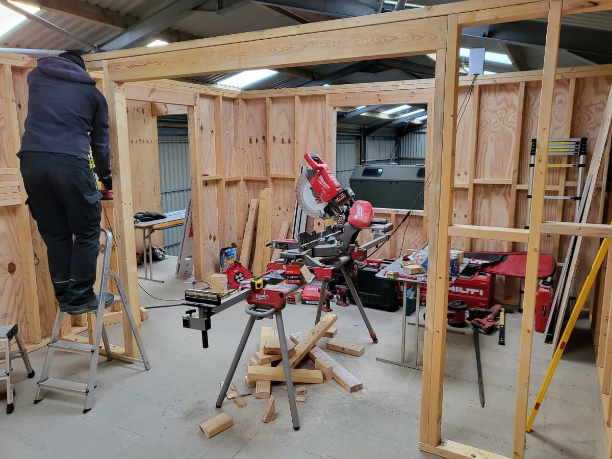
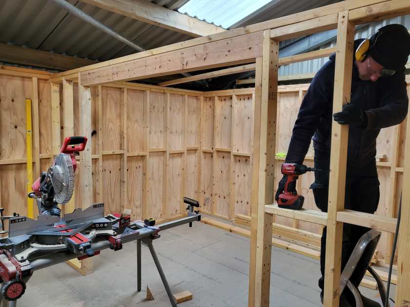
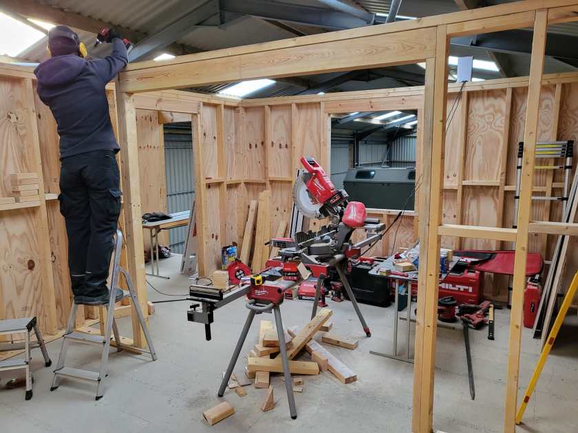
Arch for Living Room completed


Current state of our electric installation
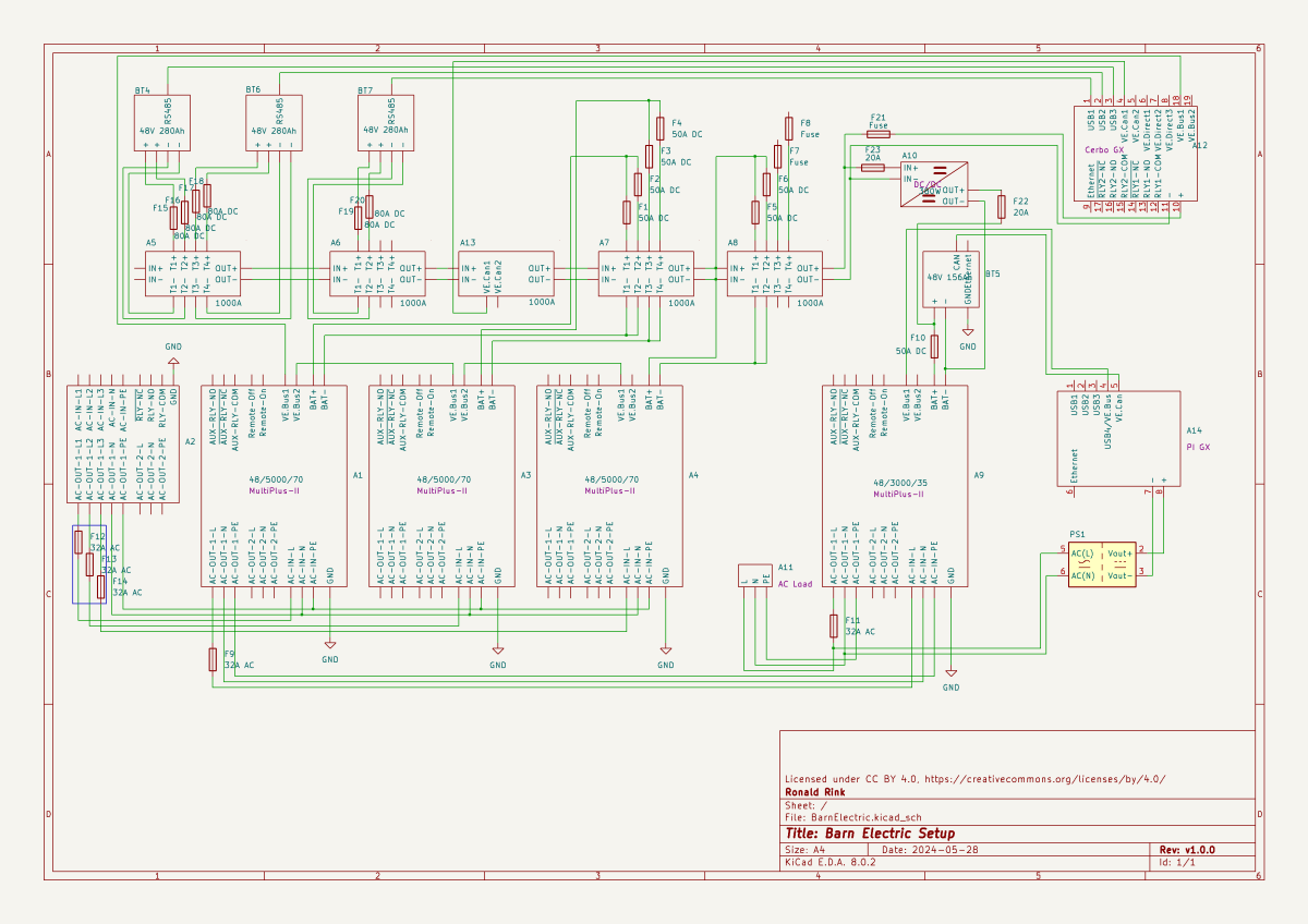
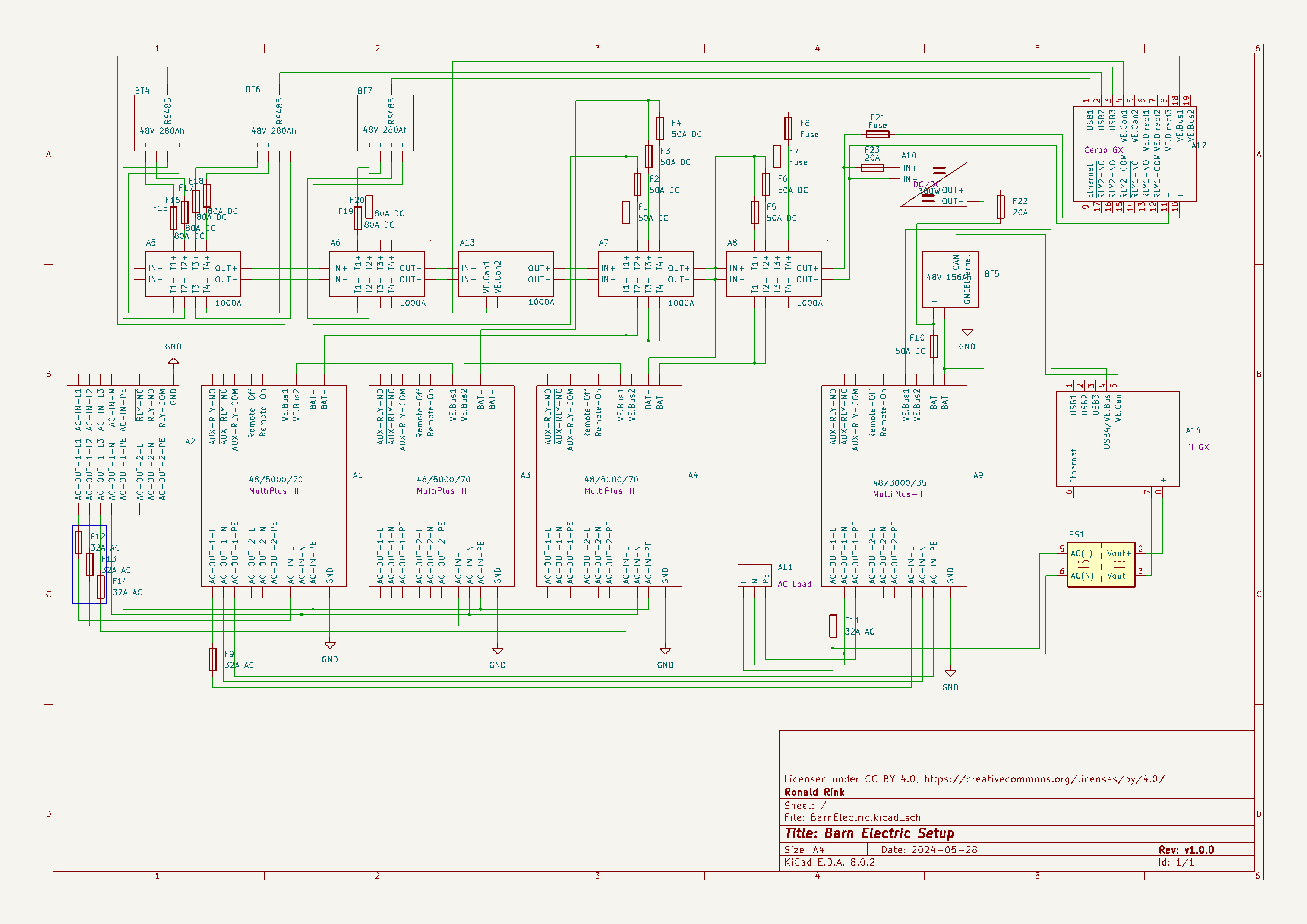
I recently wrote about our upcoming solar PV adventure. But before updating our system, I thought it was time to document and explain our current setup (with the help of KiCad).
This system is the main electricity for our barn and currently consists of three batteries with an energy (often referred to as “capacity”) of 3* 14.33kWh = 43kWh (battery bank A, A1:A2 on the plan). These batteries are charged by a JCB G20QS (B1) via three MultiPlus-II 48/5000/70 inverters/chargers (B1:C2) which are by default in “Charge Only” mode. The MultiPlus-II are configured in a 3-phase configuration but only turned on when 3-phase is actually needed.
The main power is delivered by a MultiPlus-II 48/3000/35 (B4:C5) that is connected to a separate battery bank (battery bank B, BYD LVS Premium Battery-Box with an energy of 8kWh). This latter MultiPlus-II is connected to L1 of the 3-phase MultiPlus-II. So, whenever the main batteries get charged the cascaded inverter will also be charged. In addition, we can then use PowerAssist to up to supply 8'000VA (= 5'000VA + 3'000VA) when running on batteries and up to 14'500VA (= 6'500VA + 5'000VA + 3000VA) on a single phase.
Though the generator can supply up 14'400W the chargers of the Multiplus-II can only charge with a power of up to 3* 48V* 70A = 10'080W. This is actually an advantage as the optimal efficiency factor of the generator is roughly at 12'000W. So with 210A we are pretty close. If we ever added more chargers to the system we could even slightly increase the charge current to 250A.
System A with the 3-phase inverter configuration is connected to a Lynx bus bar (A1:B4) that also includes a Lynx shunt (B3) used for measuring over all batteries. In addition, there is an islolated Orion-Tr DC-DC charger (A5) that constantly feeds system B.
System A and B are connected to their separate GX:
- system A
Cerbo GX, A5:A6
MultiPlus-II via VE.Bus, Lynx Shunt via VE.Can, JK-BMS via RS485/USB - system B
Raspberry Pi4 running VenusOS, B5:B6
MultiPlus-II via VE.Bus, BYD BMS via VE.Can (on a Pi GPIO Hat)
And this is it for the electricity installation in our barn.
Note: This cascaded setup is officially not supported by Victron, but it has been working for us without problems for months now. This might be different in your case.
Addendum
./.
Corrigendum
./.
About our new PV System
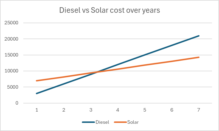
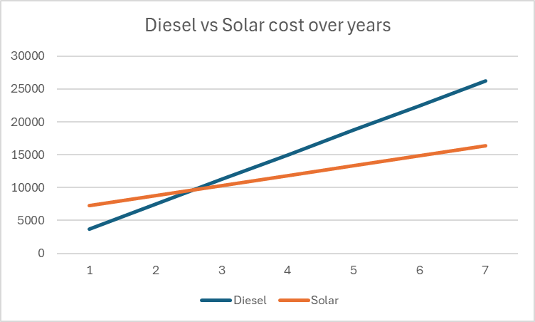
We finally did it and decided to get a PV system for our barn. Though we had been thinking about this since we started building on our plot, it never seemed to really pay off. A solar installation in very north of the Highlands?! But with prices for PV modules falling and falling I did another “business case” to see where this would land.
In the following figure you see the condensed outcome. In 38 months we would “break even” and roughly save over a 950 GBP per year over the course of seven years.
Selecting Modules for the Roof
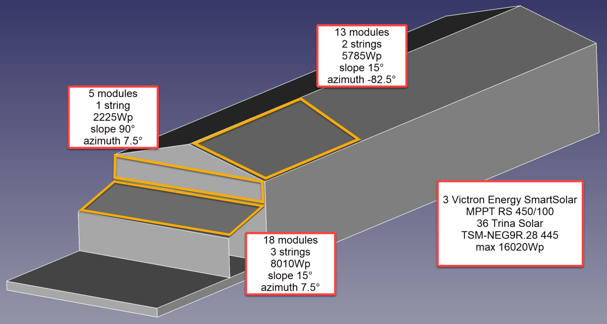
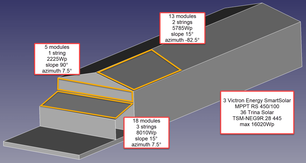
But first, let me begin from the beginning … for the last two years our JCB G20QS backup generator has been sitting outside in the rain and collecting not dust but rust – that is why we decided to build a small shelter on the south end of our barn. Once we finished drawing the shelter with its 36m2 roof, we thought that a south-facing roof would be perfect for collecting solar energy in the summer. Remembering my last calculation, I knew that the slope of the panels for winter and summer time differed dramatically. That was when we started thinking to place additional modules vertically on the south wall of the barn.
After we realised how much sheet metal for roofing would cost, we looked for for cheap solar modules that could be used as a cover for our shelter. We selected the Trina Solar TSM-NEG9R.28 445Wp module with dimensions of 1762mm x 1134mm x 30mm that would fit well as a roof.
Selecting MPPT Chargers
With the PV modules selected I had to choose between a AC-coupled and an DC-coupled system or a mix between the two. As our system is off-grid and I expected fast-changing workloads in our environment I decided for a completely DC-coupled system.
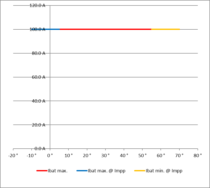
Already running a Victron system, I wanted to use Victron MPPT chargers for the installation. After checking and comparing the prices of different chargers (with a VE.Can or a VE.Direct connection), I started the Victron Energy MPPT Calculator and added my solar panels to it. I then did a couple of modifications to the spreadsheet (by prior removing the password and protection from the sheets) and found the Victron Energy SmartSolar RS 450/100 to be the best choice. With this charger I could fit 7 modules per string in order not to exceed Voc. The power would be limited by over 30A at minimum temperature but I do not expect much sun in the colder months anyway. At max temperature there would also be a cap by roughy 15A but I expect to have large amounts of excess energy during the sunnier months – so need to worry.


Note1: there seems to be a bug in the spreadsheet version BHO 01-2021 4.0 when using the “MPPT RS” tab. The calculation table uses the selected voltage in cell E15 from the “Blue- & SmartSolar” tab (and not 48V as the only possible voltage for the RS) and from there miscalculates the currents.
Note2: when selecting the number of modules and the diameter of the cabling, the up/down buttons do not seem to work correctly. Typing the values directly into D16, D33, K18, J35 and K35 works around this issue.
Module Placement
To get a better understanding where to place the modules and what difference it would make, I used Photovoltaic geographical information system (PVGIS) of the European Union (see also my earlier article More Power on how to use it).
After selecting the location of our barn I tried different combinations an panels with these constraints:
- slope of the existing barn is
15° - barn roof can fit a maximum of
28panels - azimuth of the barn is
7.5° - azimuth of the shelter is therefore also
7.5° - maximum slope of the shelter roof is
15°in order to maximise the number of vertical modules - shelter roof can fit a maximum of
18modules - south wall of the barn can fit a maximum of
5modules

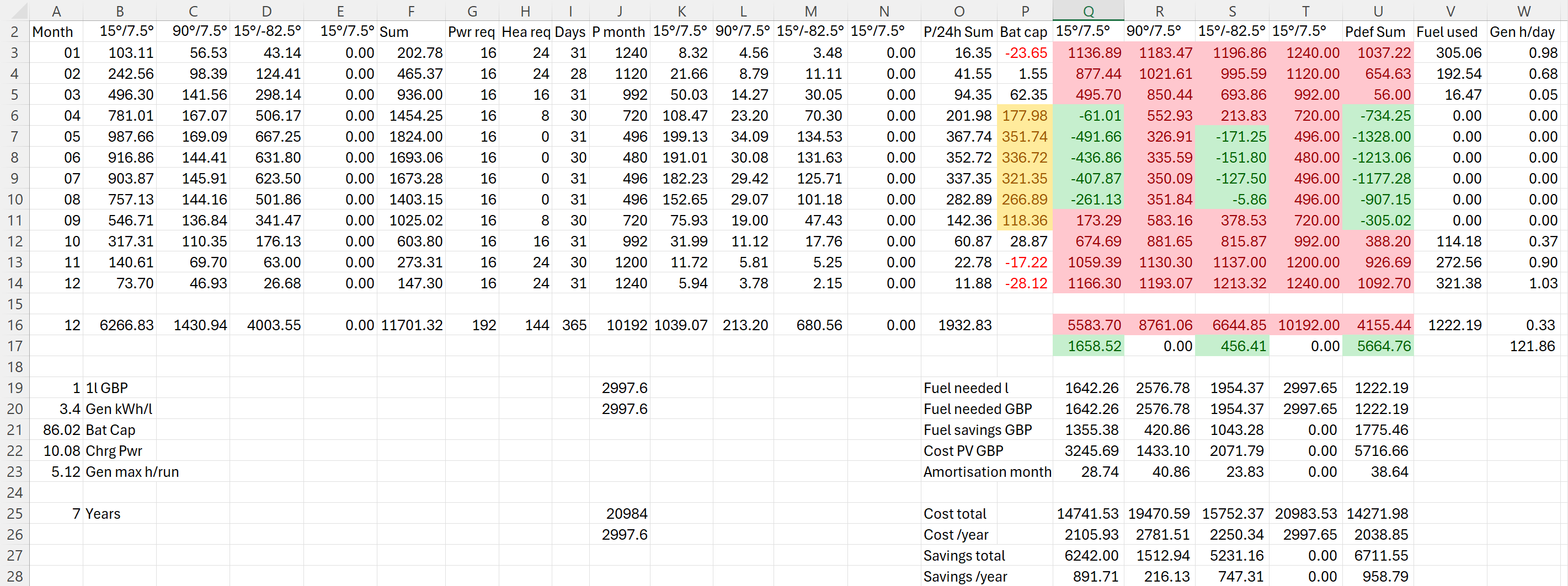
Power Prediction
I then combined the info into a table to see if and how much energy could be produced. For this I estimated the amount of energy I would need in the forseeable future per month (electricity and heating) which varies between 480kWh and 1'240kWh.
Note: currently we do not need even 25% of that amount.
The numbers with red background reflect the energy deficit for that month. Numbers with green background show an excess power production for that month. The total of all panels is shown in column U. From there it is compared against our generator which would roughly need 0.3l/kWh (row 26).
So, for the first part of the installation I will add 36 modules on 6 strings as you can see from the image below.
Anticipating Change
It is interesting to see how a 25% increase of diesel cost changes the picture:
As we still have space for more modules on our east-facing barn roof, I could add another set of (larger) modules. And this would reduce fuel consumption by approx. 20% by deferring the “break even” to 55 months!

But it gets interesting when we take rising fuel cost into account.


With these additional modules we could run the whole winter with only one filling of our diesel tank and thus avoiding a costly refill during the winter season. So, this is something to be considered for the future.
Distributing Modules
Before wrapping it up, I will quickly motivate why I chose three SmartSolar RS 450/100 instead of one SmartSolar RS450/100 and one SmartSolar RS 450/200 and their connetion to the modules. With three instead of only two devices the average power reduction during a failure is only 33% instead of 50%. Power limiting is not such an issue, as the strings will be connected as follows:
- Charger 1
117.3 A min temp / 96.2A max temp
string 1: 5 modules 90°/7.5° south wall
string 2: 7 modules 15°/-82.5° east roof - Charger 2
117.6 A min temp / 96.4A max temp
string 1: 6 modules 15°/-82.5° east roof
string 2: 6 modules 15°/7.5° south roof - Charger 3
117.6 A min temp / 96.4A max temp
string 1: 6 modules 15°/7.5° south roof
string 2: 6 modules 15°/7.5° south roof
Conclusion
I certainly do not know how much energy will really be produced. But it is clear, that I will have excess power in the summer when I do not need it and not enough power in the winter when I need it.
Additionally, I merely save a 950 GBP per year – not taking into account:
- that I already have a required inverters, bus bars etc;
- any labour on my side to design and install the system;
- that the system gets more complex and error prone.
So, in reality I probably do not really save much to anything with this installation, as Diesel is still way too cheap. Though I certainly benefit from that, it is actually a shame. There should be more incentives for cleaner power generation.
As a side note: In case you missed why we went for a generator in the first place., here is why. The quote from the power company for a grid connection was way over 35’000 GBP. For this amount I can easily buy a generator, inverters, batteries and even solar modules.
And I already have an idea what to do with all the energy during the summer months that we really do not need: brewing a red ale with green energy …
Addendum
./.
Corrigendum
./.
