I never actually measured the difference in internal resistance of the ones we built and some we got with our EVE LF280K cells. Time to correct this …
The flexible busbars delivered with our cells have approximately these dimensions: 105mm * 20mm * 2mm. This should give us a surface area of 40mm2 and an ideal internal resistance of around 0.045mOhm (according to some online calculators).
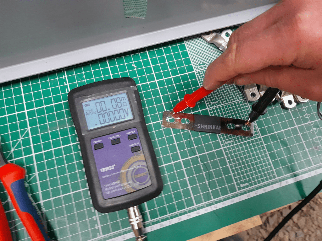
When measuring this with our trusty and highly precise TR1035+ the result displayed is 0.08mOhm.
Pre-built busbars 105mm * 20mm * 2mm
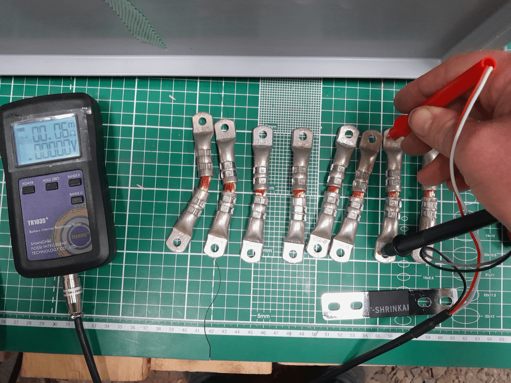
The Klauke version which comes with tinned copper lugs gives us a reading of 0.06mOhm – despite the smaller cross-section of 35mm2. The ideal internal resistance of the copper wire could be expected to be around 0.051mOhm (according to some other online calculator), so we are much closer to the measured value.
Custom busbar 105mm * 35mm2
The display error of the TR1035+ is expected to be similar as the measured range of both busbars is quite similar. There is certainly quite an amount of uncertainty (not only due to the maximum resolution of 10uOhm) to it. But it is interesting to see that the resistance of the custom busbars seems to be lower despite its smaller cross-section – while being better insulated (not seen on the picture) and more flexible at the same time (as it can be bent in more directions).
Producing these custom busbars is certainly more expensive (a single lug costs around 1.17GBP or 1.27CHF) and involves more manual and time consuming labour. However, it is quite easy to double them and/or increase its cross-section to up to 70mm2 per wire (when using multi-stranded DIN EN 60228 conductors).
So, this is it for today with fascinating facts about busbars for LiFePO4 cells.
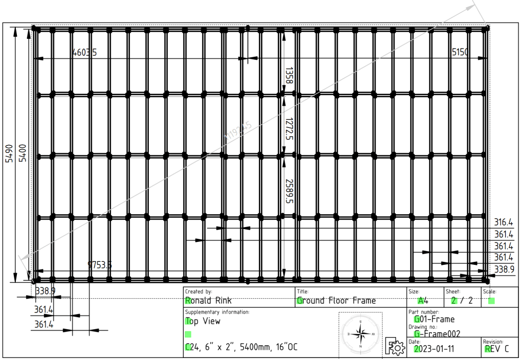
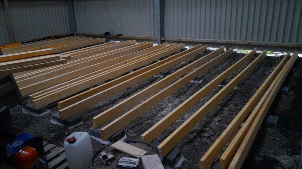
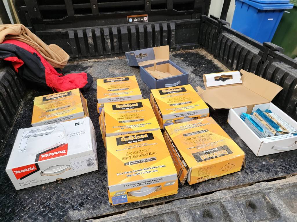
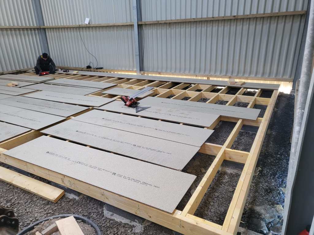
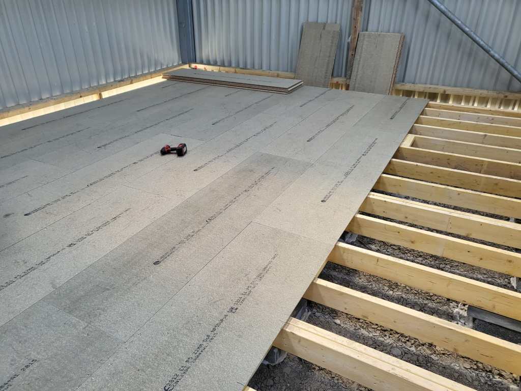
Last year in December, I started the drawings (with FreeCAD) for our “house-in-house” build: a wooden compartment inside our barn for electricity, water, storage and the like. But somehow, I never started it because of my mental concrete block (pun intended). This changed when a colleague of ours came by and helped me with laying the concrete pads. And from there we did the frame and the floor in less than 2 days – thanks to our Milwaukee Nailer and Larry Haun with his book The very efficient Carpenter.
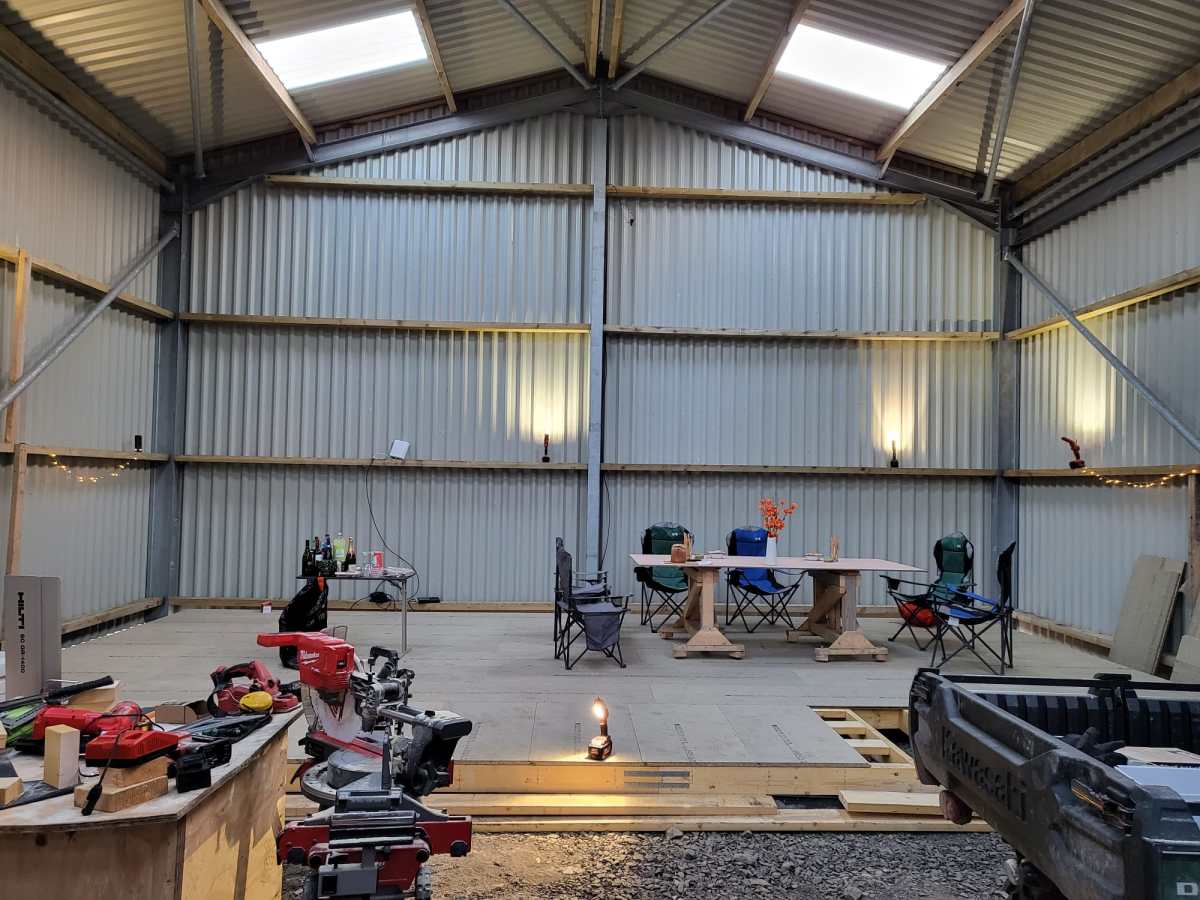
Of course, there were some gotchas and mistakes needed to be fixed. But all in all it went really well. So well, that in fact we could have our first BBQ on the new platform (and not in the dust as usual).
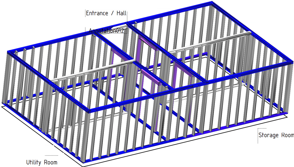
So, below you find some pictures and drawings of the “house-in-house” and the making of the platform of the ground floor.
Overview of ground floorGround floor frame resting on padsFrame of ground floor Getting the pads in placeStarting with the frameNails – the more, the betterNow only the blocks are missingInspection of our work so farThe frame is doneGround floor with the first tow of OSB sheetsGetting somewhereFinally, a table not in the dust
This is sort of a never ending story for me – just as the installation of our workshop container on the truck bed by our trusty mechanic which has been “in the making” since October 2022.
It is clear that we want and need electricity in the container. Just how and how much is not clear yet. In the following, I will consider our rquirements and different apsects and constraints of the electrical installation to hopefully come to a conclusion. This is a rather dry article with a lot of numbers – so beware …
Here is what we know (or at least think we know):
The truck has a 24V system
Charging any “leisure” batteries via the truck engine on a regular basis does not seem to be a good idea, as the fuel consumption is already 33l/100km without the container (that makes an astonishing 8.56mpg in the UK)
It is a EURO0diesel so we will not be able to get into all the cities (regardless of its problematic weight, length, height and width anyway).
Solar panels are still no real option (most of the time too way up in the North)
Charging from an EVSE might not always be possible as most of these EVSEs are for cars and do not have space for trucks
We want to be able to cook and wash in the vehicle
We will have a 2kWdiesel heater
We will have a 900W single phase petrol generator
We will be using Eve LF280K cells
The inverter must at least provide 2'250VA or 1'800W (concurrently, but not neccessarily on a single phase)
(optional) We would like to have 3-phase power in the container (as the cabling is already in place) – but also we know we would only use it very seldomly (such as for welding, then we need at least 11A per phase)
We would like to be able to charge 60% of the batteries (from 20% to 80%) within 3h
Refrigerator (able to run on 12V DC/24V DC or 230V AC)
Microwave (1'000W)
Water heater (immersion heater with 1'000W or 2'000W and/or kettle with 2'000W)
Table grill (1'250W)
Steam cooker (450W/900W)
Bread baking machine (600W)
Coffee machine (1'150W)
Washing machine (750W)
Water pressuriation system (850W)
Computers peripherals (USB-C charging with 36W via AC or DC, or 60W AC)
Lights (12V or 24V DC)
Water pump (12V or 24V DC)
Fan (12V or 24V DC)
Diesel heater (12V DC)
Starlink (60W AC, possibly 48V DC)
Infrared heating panel (150W AC)
Battery charger (12V/24V DC or 230V AC, depending on model)
Other USB powered and/or chargeable devices (via 12V/24V DC or separate 230V AC charger)
built-in 6t winch (powered by engine)
(optional) electric shower (8'000W)
Sizing the electrical installation comes with a number of additional constraints:
The crane in the workshop garage can lift up to 500kg this mean, all batteries, inverters, washine machine and water tanks must be less that weight
No single battery can charge or discharge with more than 140A
We can only charge from EVSEs with a Type 2 connector
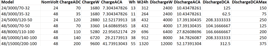
A 12V system is very quickly out of the picture (and the largest and only MultiPlus-II with 12V is a 3’000VA system). Besides, the truck has 24V system anyway. So it is either 24V or 48V. Here is an overview of all current 24V and 48V MultiPlus-II models and their charge and discharge values:
MultiPlus-II 24V and 48V
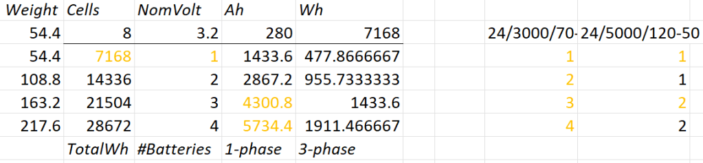
Let’s first evaluate a 24V system:
Combination of 24V batteries and invertes
1* 8s battery
Capacity is likely to be too small
Single battery is not redundant
1*3’000VA can draw too much discharge current
1* 5’000VA can draw too much discharge current
2* 8s battery
2* 3’000VA can draw too much discharge current
1* 5’000VA possible
3* 8s battery
1-phase charge requirement can only be met with EVSE 7kW 32A Type 2
3* 3’000VA can draw too much discharge current
2* 5’000VA can draw too much discharge current
4* 8s battery
1-phase charge requirement can only be met with EVSE 7kW 32A Type 2
4* 3’000VA can draw too much discharge current
So, in a 24V 1-phase system only the 5'000VA inverter would be possible with either 2 (14’336Wh) or 4 (28’673Wh) batteries.
For a 3-phase setup to support our Kemppi Kempact 253A we would need at least 4 batteries and 3* 5'000VA inverters.
And now let’s have a look at a 48V system where we have a couple of more inverter options:
Combination of 48V batteries and inverters
1* 16s battery
Single battery is not redundant
2* 3’000VA inverters needed
1* 5’000VA inverter possible
1* 8’000VA can draw too much discharge current
1* 10’000VA can draw too much discharge current
1* 15’000VA can draw too much discharge current
2* 16s battery
1-phase charge requirement can only be met with EVSE 7kW 32A Type 2
3’000VA not as 3-phase setup feasible (otherwise 6 devices necessary)
8’000VA only as 3-phase setup, but then too heavy
1* 10’000VA possible
1* 15’000VA can draw too much discharge current
3* 16s battery
1-phase charge requirement cannot be met
charge requirement can only be met with 3-phase EVSE (16A or 32A) Type 2 (11kW+)
3’000VA possible, but too heavy with combined battery weight
5’000VA possible
8’000VA only as 3-phase setup, but then too heavy
10’000VA only as 3-phase setup, but then too heavy
15’000VA possible
4* 16s battery
batteries too heavy
1-phase charge requirement cannot be met
charge requirement can only be met with 3-phase EVSE (16A or 32A) Type 2 (11kW+)
3’000VA too heavy with combined battery weight
5’000VA too heavy with combined battery weight
8’000VA only as 3-phase setup, but then too heavy
10’000VA only as 3-phase setup, but then too heavy
15’000VA only as 3-phase setup, but then too heavy
So, this leaves us with really 3+2 choices:
2* 8s (14’336Wh) batteries in a 1-phase system with a single 5’000VA inverter
Battery and inverters would weigh roughly 140kg
2* 8s (14’336Wh) batteries in a 3-phase system with three 5’000VA inverters
Battery and inverters would weigh roughly 250kg
Not possible for 3-phase welding
4* 8s (28’672Wh) batteries in a 3-phase system with three 5’000VA inverters
Battery and inverters would weigh roughly 310kg
1* 16s (14’336Wh) battery in a 1-phase system with a single 5’000VA inverter
Battery and inverter would weigh roughly 140kg
2* 16s (28’672Wh) batteries in a 3-phase system with three 5’000VA inverters
Battery and inverters would weigh roughly 310kg
3h on a 1-phase 16A Type 2 would charge about 38% (a 60% charge takes 4.7h)
From there, we can narrow this down even further:
1-phase system: 24V, 2*8s
Price: batteries 2* 1’364GBP = 2’728CHF plus inverter 1* 1’359GBP total = 4'087GBP
Con: 24V MultiPlus-II are considerably more expensive (than 48V)
Con: only have the capacity
Con: cannot run electric shower
3-phase system: 48V, 2* 16s
Price: batteries 4* 1’364GBP = 5’456CHF plus inverter 3* 812GBP = 2’436GBP total = 8'802GBP
Con: charge requirement can only be met with 32A Type2 on 1-phase
Con: additional 48V|24V DC-DC converter required
Con: heavier, 300kg+ Con: higher self-consumption in 3-phase configuration
So – drum roll – my conclusion: for roughly double the money in a 48V we would get double the capacity and triple the charge and output power and pretty much can do everything we want the system to be able to do.
The 3-phase system can be reconfigured to a parallel 1-phase system, so we would even be able to use an electric shower (though very unlikely – we have our mobile shower). We can either charge 1-phase or 3-phase and have a longer window of electric autarky. And for most of the time we would leave the system in a 1-phase single device InverterCharger configuration. And additionally, for charging the other 2 devices would bet set to ChargeOnly (but be configured independently configured from each other).
The exact setup I will have to layout some other time, but right out of my head I would think of the following components:
External power in with CEE 16-5, CEE32-5, CEE32-1, CEE16-1 and Neutrik PowerCON True1 TOP (the more the better) connected to an ATS
AC out from MultiPlus-II connected to ATS
Orion-Tr 24V|48V DC-DC converter charging from alternator (though not the norm)
Orion-Tr 48V|24V DC-DC converter as power supply: to support 24V loads in the container as charger: as an emergency charger for the truck batteries
Lynx Power In, Distributor
Venus OS with Raspberry PI for RS-486 and DVCC
So, in case our Saurer ever gets finished – at least I know how to do the electricity …
Finally, they arrived! We now have bins from the Highland Council. This means, we no longer have to drive to the Wick Recycling Centre to dipose our waste. What a convenience! For us this is another milestone (after getting a postal address, the Planning and the barn built).
Our bins delivered by the Highland Council
As our plot is not exactly reachable by the bin men we now drive them to the main road – 440m to be exact. Though this may sound tiresome, but it is still way faster than to drive to the recycling centre.
From here to there (copyright OSMaps)The path our bins take to get emptied (copyright OSMaps)
The other day, I realised that I never wrote about the case build of our 16s 48V batteries, as I did for the 8s case and the 4s case. So, here it is – and I am actually describing 2 revisions as we made some adjustments.
First, the total weight of the cells alone would be roughly 16 * 5.3kg ~ 85kg. This is way beyond what a single person can – or at least should – lift. So, I deciced to split the battery into 2 separate cell blocks of 8 cells each (similar as I did split the 8s battery in the Toyota HiAce). With this approach, I would be able to:
reuse the 8s design (including the RAKO boxes)
be able to move or lift half a battery (which weighs roughly 53kg)
This battery has a nominal capacity of 3.2V * 16 * 280Ah = 14'336Wh and can be charged or discharge with up to 140A ^= 7'168W. We currently have 2 of these batteries running on our 3-phase setup with 3 * Victron MultiPlus-II 48/5000/70-50.
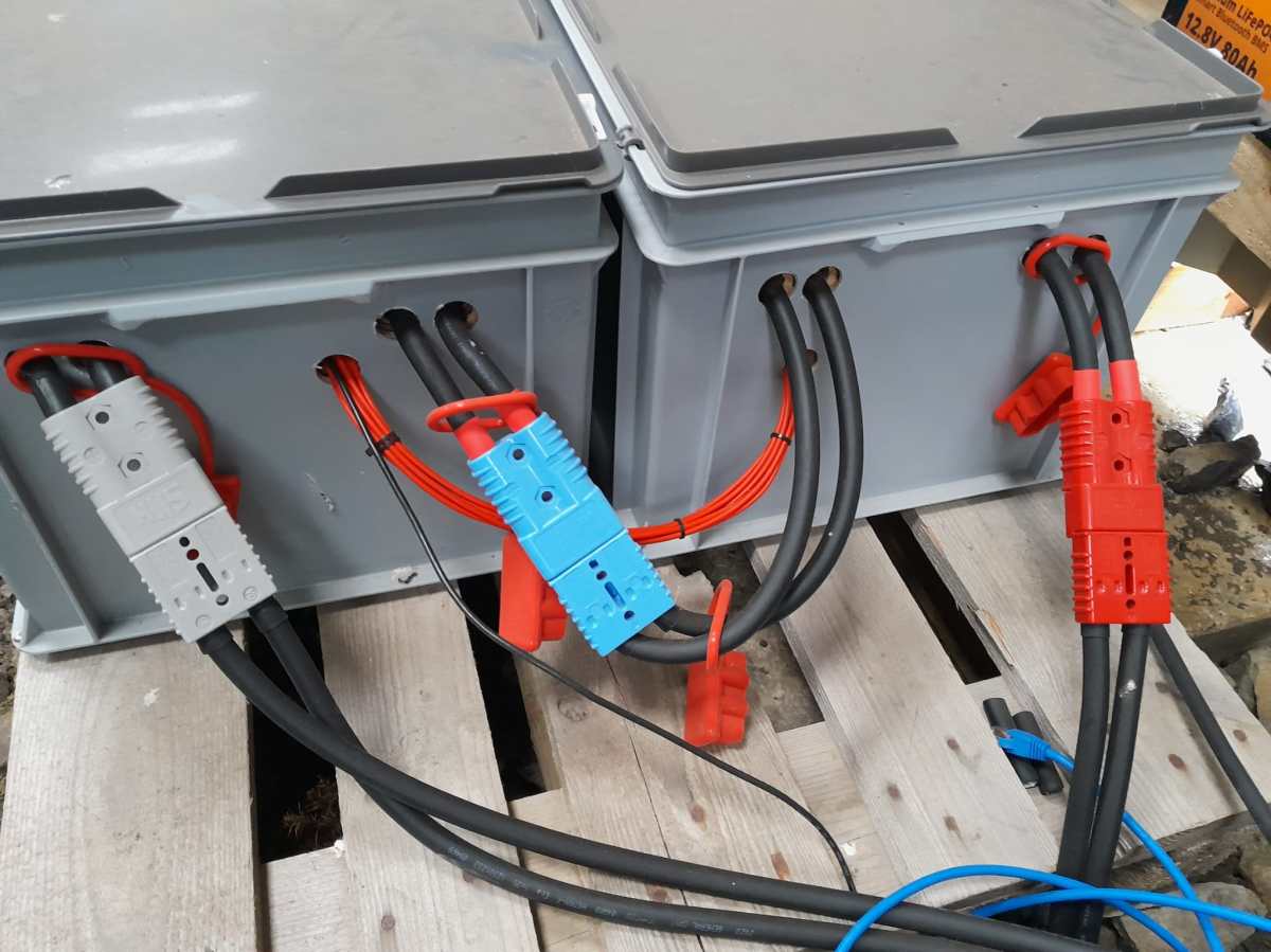
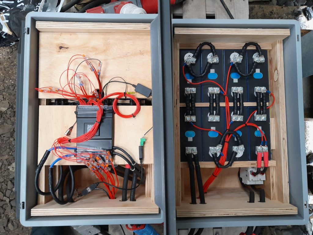
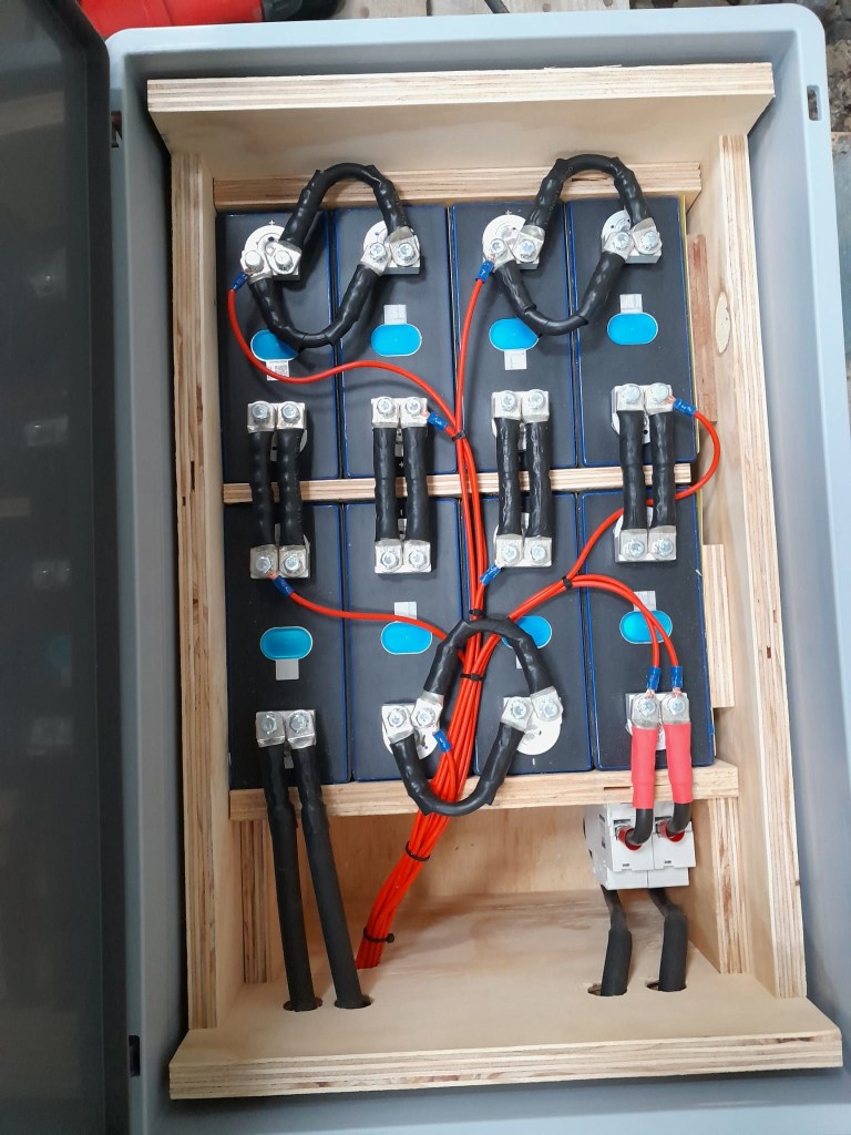
So essentially, I built 2 8s batteries with a connection cable between cells 8 and 9. The main negative and the BMS would be in one box and the main positive with the DC breakers would be in the other box. To avoid confusion, in this setup I went for coloured Anderson SB175 housings, with
Red 2 * 35mm2 H07RN-F cable main positive
Grey 2 * 35mm2 H07RN-F cable main negative
Blue Interconnecting both blocks 2 * 35mm2 H07RN-F cable connecting from cell 9 positive to cell 8 negative
In all cases
16s Battery Connectors
To connect the cells to the BMS balancer cables I extended the balancer cables with 2.5mm2 wire via WAGO 221-2411 inline splicing connectors. I then measured the increased resistance of the additional cable length and adjusted the values in the BMS configuration for cells 1 to 9.
With these inline connectors I am now able to disconnect the blocks from each other so I can move them around independently, if needed.
On the BMS, I connected a USB RS-485 TTL adapater with a USB extension cable which leads to one of the USB ports of the Victron Cerbo GX. With the help of dbus-serialbattery and BatteryAggregator I can control the DVCC settings in Venus OS.
The rest of the build is, as I already mentioned, pretty much like the 8s build.
Revision 1
Here are some images of the completed build of revision 1.
16s Battery top view16s Battery Block 1 main negative with BMS16s Battery Block 2 main positive with DC breaker
Revision 2
These are the changes I am currently making for the next revision:
add additional connectors for the balancer cables to further facilitate the disconnection of both blocks;
use 16mm2 M6 Klauke DIN46235 compression cable lugs for the connection of the main negative (cell 16) to the B- of the BMS (only relevant to the older JK-BMS), to be able to disconnect and potentionally replace the BMS;
use a WAGO 35mm2 DIN rail connector in the main negative block on cell 1/9 for the outgoing cable;
use cable glands on the external connections; (this allows for easy disconnection and re-building the block as an 8s battery);
use ratchet straps for compressing and mounting the cells to enable easier maintainability of the cells;
use Anderson PowerPole PP180 connectors instead of SB175, so I can use mounting plates for the PP180 and do not have dangling cables on the outside of the case (these connectors are expensive and increase the price of the overall build by roughly 60GBP).
In one of our previous articles I wrote about the Honda EU10i as a backup generator for charging batteries via a Victron MultiPlus. Now as the supply chain has stabilised, the only noticable downside of this generator, that it will set you back a 1'000+ CHF (and even 1'000+ GBP in the UK). As we plan to equip our HiAce, Hilux, 2DM and possibly our trailer with such a generator this really adds up. So, I started looking for something cheaper – but hopefully equally robust, enduring and sturdy.
The requirements were basically unchanged. We want a generator that
is light less than 20kg including fuel
has a sustainable output of over 3.5A @230V as the MultiPlus-II 48/5000/70 has a minimum AC input limit of 3.5A
in combination with a MultiPlus 1600VA and PowerAssist must be able to provide more than 2'000W (which is already fulfilled when delivering more than 3.5A by itself)
generates more than 1'000Wh/l
must have an internal tank
generates more than 8'500Wh with the internal tank and an additional 5l tank
must be running petrol or diesel (the latter very unlikely in that weight range)
should be quiet the less noisy the better, no hard specs here
(optional) can be paired with another model to double the output
must have an automatic shutdown in case of oil issues and overload
must have an ECO mode
manual starter i.e. no battery needed for starting the generator
a seller with a service center from UK, CH or EU (preferrably DE/AT) for filing warranty claims if necessary
On AliExpress, eBay and Amazon there are quite some models for very little money. However, I also have very little trust (if there is such thing at all) in those product offerings.
So, when I did some modern research (i.e. googling around the internet) I came across three models:
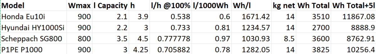
But before I go into detail here is a summary of the comparison:
Comparison of selected generators
Hyundai HY1000Si
This is the model I am most likely to buy (if I want to save money over buying the Honda EU10i).
Except for size, weight and price all its specs do not match the Honda EU10i (regardless of the slightly larger tank).
With a total advertised runtime of 3h it can produce 2'700W (which is the equivalent of roughly over a third of the nominal capacity of an 8s 280Ah battery – compared to nearly a half for the EU10i).
So unless we intend to use the generator only seldomly this would make a real (negative) difference in:
usability more frequent usage pattern, more refuelling operations
maintainability due to more service hours and material wear-off and efficiency longer runtime, more fuel consumption, more labour.
Compared to the Honda EU10i (which some consider the “gold standard”) there is relatively little information to be found about this generator (especially no thorough reviews).
Further note: From the advertised information the generator comes with some tools and replacement parts and even oil (which is an advantage over the Honda).
P1PE P1000i
Not a brand I have heard from before. It is a brand in the UK sold by the same company, GenPower Ltd, that is also the distributor for the Hyundai generators. And they heavily claim to use Hyundai engines as well. So much in fact, that at first sight it seems they *are* Hyundai generators.
The data sheet is to be questioned. A total runtime of 8.5h @50% load is advertised and no mentioning of any fuel consumption at 100% load. In the data sheet a fuel consumption of 550g/kWh is mentioned. With a specific weight of 740g/l for petrol this would equate to 0.74l/kWh which is not in line with the previous statement of 8.5h of runtime at 450W which would result in 0.78l/kWh. This would only “add up” with an assumed specific weight of 700g/l. And with petrols like E7 or E10 the specific weight will more likely further increase as in reduce. Furthermore, a generator running at 100% load is not expected to be as efficient as if it was running at 50% load. I am not saying that the 40ml/h make so much of a difference (it is slightly 5% off). I just get curious when the technical data sheet more looks like a marketing brochure. So, I would rather estimate a runtime of 4h at full load which would result in 0.83l/kWh or 1204Wh/l.
As P1PE seems to use the same Hyundai engines their increased efficiency over the HY1000Si would have to be in the “inverter” or electronics part of the generator. I do not find it likely that the cheaper model would have more efficient ingredients than the Hyundai model.
Scheppach SG800
A brand I have not heard from before either. Efficiency is not its strength and as I did not find it anywhere stocked, I merely list it here as an interesting option because of its form factor.
With only 800W this generator seems to be on the weaker end. But with only 8.5kg and a 3l tank it makes it up for its lack of efficiency and output capacity.
This might be an option where one really only rarely uses the generator. And then only to charge a battery (which is exactly what we aim for).
The price is debatable as I could not find it anywhere ready for order.
Summary
The choice for these small generators is rather small. If we were open for larger and heavier models the 2'000W range of inverters would provide a much broader selection (also with a higher price tag).
So, to come to a conclusion: it’s mainly price over efficiency and loudness. Is the spending of 2.5 times more justified for a generator which I only want to use in edge cases? For our use case, probably not.
Though this could have been our first “unboxing blog post” in this article we only describe an already unboxed table grill.
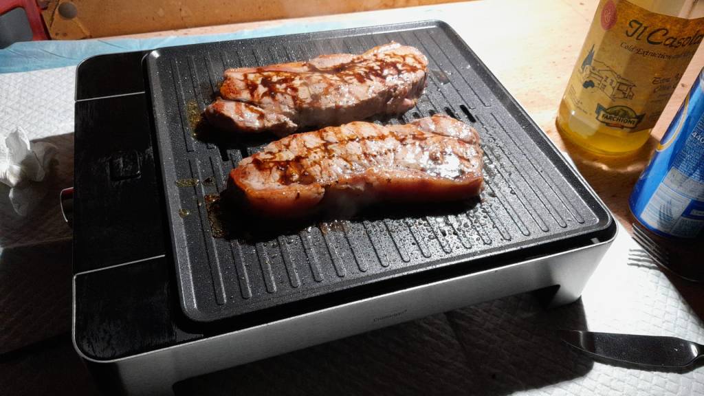
Being able to have fires in the open less and less often it was time to find an electric BBQ alternative – with the constraint that it should run on a Victron MultiPlus Compact 24/1600/40-16 (or any other 1600VA sized inverter). After some frustration we finally found a nearly perfect match: the WMF Lono Quadro.
According to its spec sheet and product brochure, it uses 1250W – which is just under the nominal maximum power of 1280W that the MultiPlus can deliver.
Plus, the BBQ is relatively cheap. With a MRSP of 79.99 EUR it is available for as low as 60 EUR (PP included depending on your location). So, we ordered one of these table grills and gave it a try.
Upon powering up the device it uses its full power (regardless of the dial setting 1 .. 5) which results in a current draw of around 50A as seen on the BMS. The setting of the dial only seems to affect the intervals between heating (drawing current at 50A) and not heating (not drawing current at all).
The initial heating phase lasts naturally longer which results in the fan of the inverter kicking in at some point. But once the BBQ is at its operating temperature the fan is silent most of the time (as the heating intervals are relatively short). With 1250W nominal power consumption and a heat-up time of around 5min this consumes roughly 104Wh – about the same energy to boild 1.1l of water from 20°C.
During the use of the BBQ the inverter is pretty much at its power maximum and so has little to no resources left to power anything else. Though it seems possible to leave a fridge running, it might be better to unplug any consumers during cooking.
But all in all, with this table grill we now can do the BBQ inside (or outside) in our Toyota HiAce – even when we are on the move.
Some additional observations:
Weight The device is relatively heavy – especially the grill plate.
Size The usable size of the BBQ (270mm x 270mm) in relation to its overall dimensions seems quite large (while the whole device is still not bulky).
Power consumption Though the power consumption is rated at 1250W the heating intervals are relatively short which turn leads to a moderate overall power consumption.
Cleaning The grill plate can easily be removed and thus easily be removed (even in a dishwasher if you happen to have one in your car). Also, the drip tray can easily be removed and cleaned. Only the base plate is not meant for dishwashing.
Drip tray If the BBQ is not positioned horizontally (maybe due to the parking position of the vehicle) then the drip tray might have difficulties to catch all the fat that might float around the grill plate.
And this is it for today. Happy BBQing …
WMF Lono Quadro running from a Victron MultiPlus Compact 24/1600/40-16 at roughly 1250W/50AHeat-up time is roughly 5min when turning the dial to the maximum position
However, in this case we wanted a kind of “special” setup which included the use of MultiPlus Assistants. So, in this article I will quickly describe what we wanted to achieve and how we implemented it.
In general, when connected to shore power we want to be able to limit the AC current drawn from the shore power. This is easily accomplished by setting a limit on the MultiPlus itself – or, as in our case, via the VE.BusSmart Dongle. Though the Phoenix does have a VE.Direct interface and is able to be connected to a GX device, in our setup we did not want to use a GX device. So, essentially the Phoenix can only be controlled via Bluetooth and the VictronConnect app. But configuring the AC input limit on two devices (Phoenix and MultiPlus) is not only a nuisance from a usability standpoint, but also error-prone as one (or at least we) tend to forget things quickly. So, a different and better solution was needed.
Enter the MultiPlus Assistant in form of the Programmable Relay. With this, we can configure the built-in relay of the MultiPlus to open and close based on the availability of an AC input.
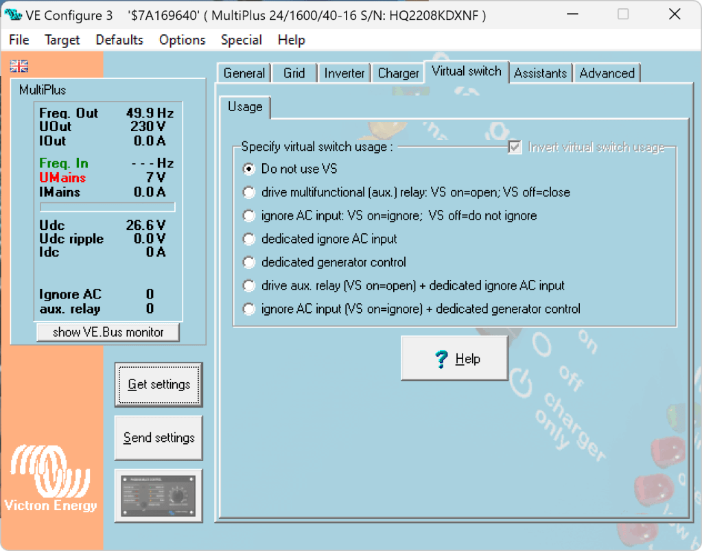
Note: we have to disable “Virtual Switch” in the MultiPlus to be able to use the MultiPlus Assistant.
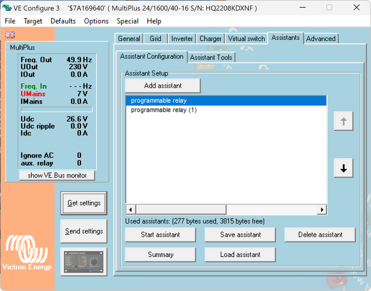
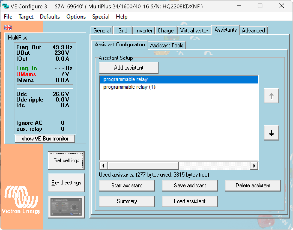
The Phoenix has a Remote Input connector, that can be used to stop charging when the connection is “off”. So in our case, we enabled two Programmable Relay assistants:
Programmable Relay, NC – On/Open After 5 seconds of AC input on the MultiPlus the relay is opened.
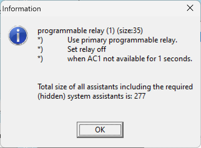
Programmable Relay, NC – Off/Closed After 1 second of no AC input on the MultiPlus the relay is closed (which is the default state).
Below you find some screenshots with the configuration in VE Configure:
Disable Virtual Switch on MultiPlusAdd 2 Progammable Relay assistantsProgrammable Relay ON after 5 secondsProgrammable Relay OFF after 1 second
So, five seconds after the MultiPlus has power via AC input it will open the relay which in turn will enable the Phoenix to start charging.
One second after AC input is gone the MultiPlus will close the relay so the Phoenix will stop charing (if it was charging at all).
The AC input of the Phoenix is connected to the AC output of the MultiPlus. So, when there is a AC input limit configured on the MultiPlus (such as 3A @230V) the MultiPlus and the Phoenix will not be able to charge with more than 3A. And from the MultiPlus perspective, the Phoenix is just an arbitrary consumer.
This can lead to some undesired behaviour if we were to limit the AC input to e.g. 1A. In this case, the MultiPlus would – when in Inverter mode – draw from the battery so the Phoenix could charge the battery. perpetuum mobile … ? And when the AC input is gone, this means that for roughly one second the Phoenix will also charge form the battery. But this is something I can live with easily.
And if we really had a very low power AC input (of e.g. 1A) we can still unplug the remote input and force the Phoenix not to charge. Or manually switch the MultiPlus to Charger mode only.
For us this is a usable solution without the need for multiple configuration changes nor the presence of a GX device.