

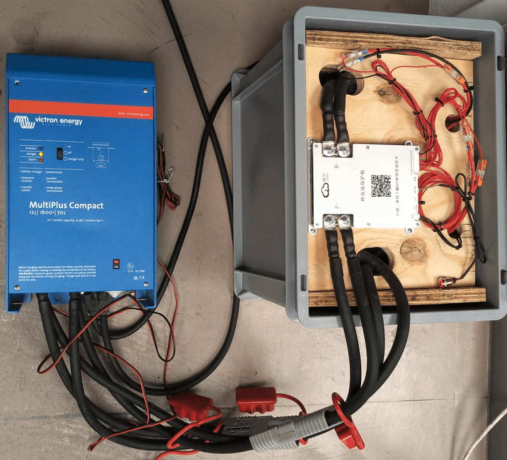
Based on our Eve 8s design, I made a sketch for a 4s 12.8V battery, which I could later connect to a Victron MultiPlus Compact 12/1600/70-16:
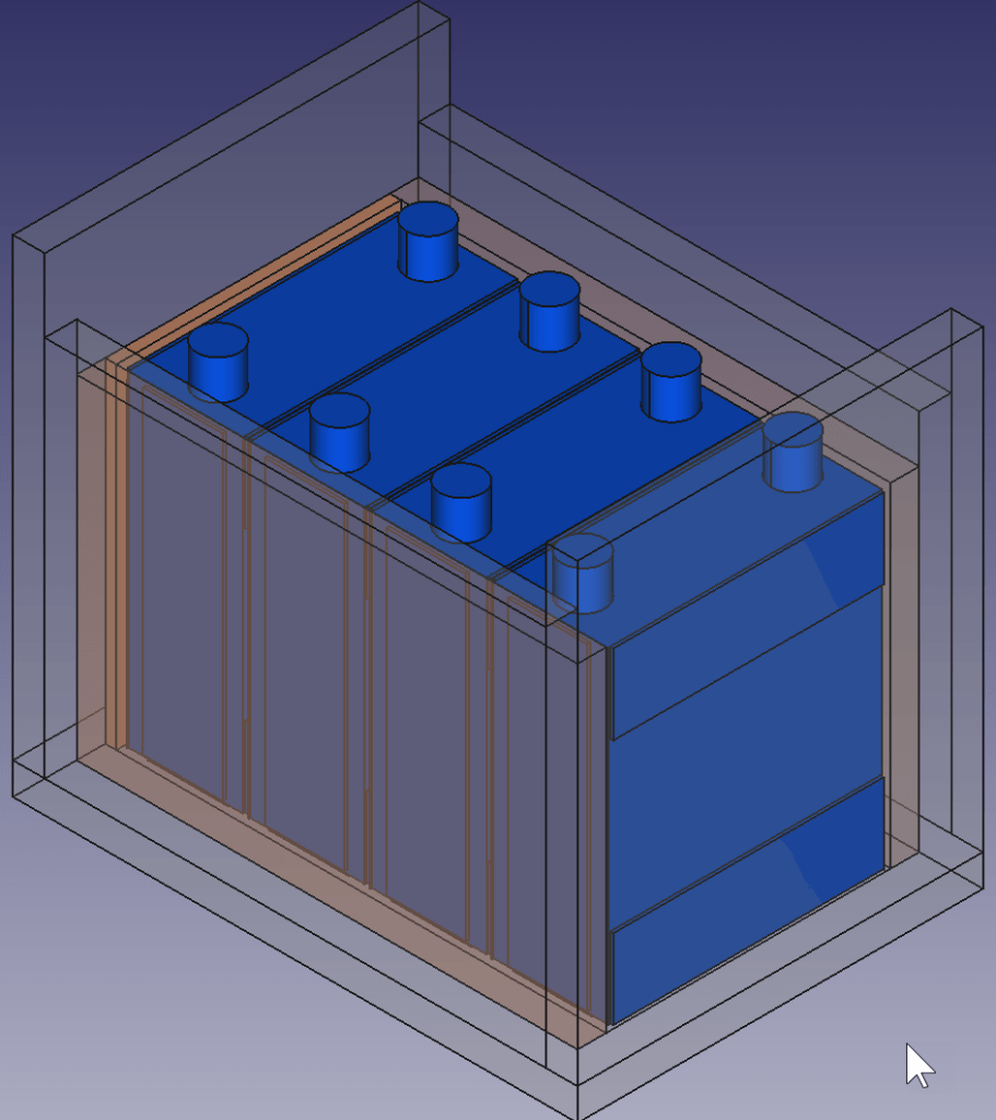
Again, this battery has a wooden inner case and sits inside a utz 400mm x 300mm x 325mm RAKO container.
There are a few differences however:
- There is no space for fuses inside the container
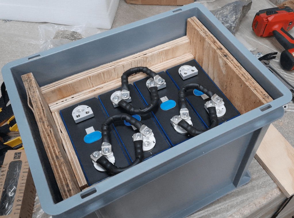
(so it is more like a traditional battery); - all bus bars are “bent” and not straight
(we need three35mm2pairs, so six cables altogether); - main positive and main negative are on the opposite sides of the cells;
- I use a JK-BMS B2A8s20P without soldered cables but with dual
M6threads
(so I can use 35mm2 cables all the way).
To cut the plywood in an efficient way, I used a web site called cutlistoptimizer which gave me this result:
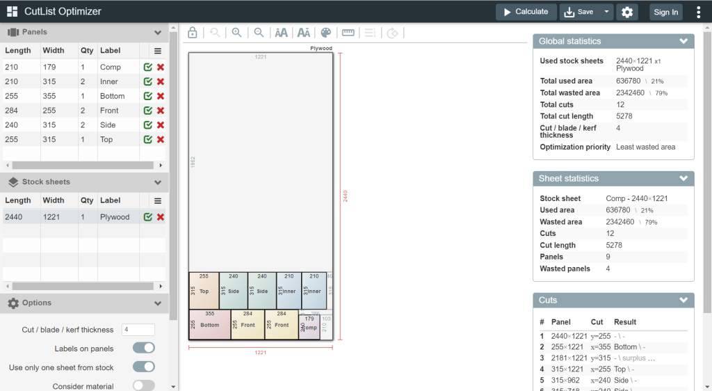
For this build, I planed all the boards after cutting, before putting in the cells. With this, I hoped to minimise the chance of any particles on the board damaging the cell insulation.
And for the small board at the short side of the case, I did also use 20mm plywood, but planed it several times until it I could just slide it in.
This is how the wooden case looks with the cells and insulation boards (shown in red):

Note: when using a JK-BMS I found it important to have the main negative connection point on the upper left (or lower right). Only with this orientation it was (relatively) easy to connect the cell to the BMS.
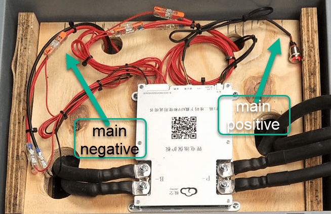
It needed some fiddling to get the main negative cable pair to the BMS and the main positive cable pair out of the frame, as we can see from the image above.
The connection to the individual cells are fed through WAGO 221-2411 2 conductor inline splicing connectors. The holes into the top board were done with a forstner bit and a jigsaw. This version of the BMS can be fixed with four screws to the board (so no need for wire straps as with the 24s version).
Again, instead of a display I just used the pluggable power button that is connected to the display port of the BMS to power on and off the device.
In the end, I added Anderson SB175 connectors and 1383 (2AWG) contacts to both pairs and connected them to the inverter.
Some more details
- All 35mm2 cables are Eland H07RN-F flexible rubber cable;
- compression cable lugs are Klauke M6 35mm2 DIN46235;
- cell contacts were secured with M6 serrated washers and M6
16mmsteel bolts; - BMS threads B- and P- were secured with M6 lock nuts to M6
16mmsteel bolts (with the bolt upside down); - cell wires from the BMS were fitted with uninsulated ferrules;
- cell wires on the positive cell poles were fitted with ring lugs and a
2.5mm2hookup wire; - I added handles to the SB175 connectors to facilitate disconnecting the cable pairs;
- I added dust covers to the SB175 connectors;
- all compression cable lugs and the SB175 were crimped with a Hilti NUN54-22;
- all cable lug connections and Sb175 were heat shrinked;
- I added 2*35mm2 cable pairs with SB175 connectors to the inverter by replacing the existing 35mm2 welding cable with
M8lugs (you still need M8 lugs on the inverter positive and negative terminals).
Things to improve next time
- Mount the SB175 connectors to the outside of the container
With this the lid can be closed and the cables and BMS are better protected against pulling; - add
3Ainline fuses to the cell wires; - use
45°angled cable lugs for main positive and main negative to make it easier to get the wires routed outside the container; - feed an additional wire pair for the voltage sensor from the main positive outside the container to be able to connect it to the inverter (but I am not too sure about this, as I think the voltage drop on the 2*35mm2 connection is neglectable – it might better to add a temperatur sensor to the main positive):
- maybe add protective wire sleeves to the SB175 connectors (but they are quite expensive):
- add a Victron MK-3 USB-C interface with RJ-45 cable into the case (to be able to restrict AC power on the inverter).
What did it cost?

Summary
This case is not as complete as the 8s version – due to its form factor. Neither the inverter has an RCBO nor the battery has a DC MCB. This has to be added separately (incurring additional cost and space). As written above, the 4s version is more like a traditional battery. However, the form factor is quite compelling; 3.5kWh in 400mm x 300mm x 325mm case. Especially in combination with the compact edition of the Victron MultiPlus. And the cost (as always without labour) is very reasonable, as well.
The inverter delivers 1200W constant power – in my opinion, enough for a small and mobile electricity build. Runnig a Krups Inissia Nespresso machine is not a problem, and boiling water with our 1000W immersion heater neither. Worst case, you could also run a 300W infrared panel heater for more than 11 hours.
One drawback of the inverter is probably the relatively small charger. With 70A at 12V it can only charge the battery with around 840W. This is certainly not the problem of the battery which would support charging up to 1344W.

2 thoughts on “Building a battery case for a 4s Eve LF280K configuration”